EP1283354A2 - Système d'injection de carburant - Google Patents
Système d'injection de carburant Download PDFInfo
- Publication number
- EP1283354A2 EP1283354A2 EP02016623A EP02016623A EP1283354A2 EP 1283354 A2 EP1283354 A2 EP 1283354A2 EP 02016623 A EP02016623 A EP 02016623A EP 02016623 A EP02016623 A EP 02016623A EP 1283354 A2 EP1283354 A2 EP 1283354A2
- Authority
- EP
- European Patent Office
- Prior art keywords
- fuel
- solenoid valve
- fuel injection
- injector
- return
- Prior art date
- Legal status (The legal status is an assumption and is not a legal conclusion. Google has not performed a legal analysis and makes no representation as to the accuracy of the status listed.)
- Withdrawn
Links
Images

Classifications
-
- F—MECHANICAL ENGINEERING; LIGHTING; HEATING; WEAPONS; BLASTING
- F02—COMBUSTION ENGINES; HOT-GAS OR COMBUSTION-PRODUCT ENGINE PLANTS
- F02M—SUPPLYING COMBUSTION ENGINES IN GENERAL WITH COMBUSTIBLE MIXTURES OR CONSTITUENTS THEREOF
- F02M61/00—Fuel-injectors not provided for in groups F02M39/00 - F02M57/00 or F02M67/00
- F02M61/16—Details not provided for in, or of interest apart from, the apparatus of groups F02M61/02 - F02M61/14
- F02M61/168—Assembling; Disassembling; Manufacturing; Adjusting
-
- F—MECHANICAL ENGINEERING; LIGHTING; HEATING; WEAPONS; BLASTING
- F02—COMBUSTION ENGINES; HOT-GAS OR COMBUSTION-PRODUCT ENGINE PLANTS
- F02M—SUPPLYING COMBUSTION ENGINES IN GENERAL WITH COMBUSTIBLE MIXTURES OR CONSTITUENTS THEREOF
- F02M47/00—Fuel-injection apparatus operated cyclically with fuel-injection valves actuated by fluid pressure
- F02M47/02—Fuel-injection apparatus operated cyclically with fuel-injection valves actuated by fluid pressure of accumulator-injector type, i.e. having fuel pressure of accumulator tending to open, and fuel pressure in other chamber tending to close, injection valves and having means for periodically releasing that closing pressure
- F02M47/027—Electrically actuated valves draining the chamber to release the closing pressure
-
- F—MECHANICAL ENGINEERING; LIGHTING; HEATING; WEAPONS; BLASTING
- F02—COMBUSTION ENGINES; HOT-GAS OR COMBUSTION-PRODUCT ENGINE PLANTS
- F02M—SUPPLYING COMBUSTION ENGINES IN GENERAL WITH COMBUSTIBLE MIXTURES OR CONSTITUENTS THEREOF
- F02M55/00—Fuel-injection apparatus characterised by their fuel conduits or their venting means; Arrangements of conduits between fuel tank and pump F02M37/00
- F02M55/002—Arrangement of leakage or drain conduits in or from injectors
-
- F—MECHANICAL ENGINEERING; LIGHTING; HEATING; WEAPONS; BLASTING
- F02—COMBUSTION ENGINES; HOT-GAS OR COMBUSTION-PRODUCT ENGINE PLANTS
- F02M—SUPPLYING COMBUSTION ENGINES IN GENERAL WITH COMBUSTIBLE MIXTURES OR CONSTITUENTS THEREOF
- F02M55/00—Fuel-injection apparatus characterised by their fuel conduits or their venting means; Arrangements of conduits between fuel tank and pump F02M37/00
- F02M55/004—Joints; Sealings
- F02M55/005—Joints; Sealings for high pressure conduits, e.g. connected to pump outlet or to injector inlet
-
- F—MECHANICAL ENGINEERING; LIGHTING; HEATING; WEAPONS; BLASTING
- F02—COMBUSTION ENGINES; HOT-GAS OR COMBUSTION-PRODUCT ENGINE PLANTS
- F02M—SUPPLYING COMBUSTION ENGINES IN GENERAL WITH COMBUSTIBLE MIXTURES OR CONSTITUENTS THEREOF
- F02M55/00—Fuel-injection apparatus characterised by their fuel conduits or their venting means; Arrangements of conduits between fuel tank and pump F02M37/00
- F02M55/007—Venting means
-
- F—MECHANICAL ENGINEERING; LIGHTING; HEATING; WEAPONS; BLASTING
- F02—COMBUSTION ENGINES; HOT-GAS OR COMBUSTION-PRODUCT ENGINE PLANTS
- F02M—SUPPLYING COMBUSTION ENGINES IN GENERAL WITH COMBUSTIBLE MIXTURES OR CONSTITUENTS THEREOF
- F02M2547/00—Special features for fuel-injection valves actuated by fluid pressure
- F02M2547/003—Valve inserts containing control chamber and valve piston
Definitions
- the invention relates to a fuel injection device with an injector and a solenoid valve to control the injection process.
- a solenoid valve to control the injection process.
- Solenoid valve control solenoid
- the installation space i.e. 90 ° to the injector, flanged to the injector housing.
- Venting the armature space of the solenoid valve presents problems.
- Known fuel injection device is proposed on a End of the solenoid valve facing away from the injector provided. This can lead to installation space problems. Finds an insufficient one Venting, d. H. formation of air bubbles in the anchor space occurs a lack of damping in the absence of fuel. The anchor tilts in such cases to vibrations.
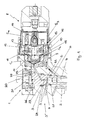
- FIG. 1 shows the structure of part of a fuel injection device 1 is visible.
- the general structure of such a fuel injection device 1 is known and is described, for example, in EP 0 907 018 A2. Therefore, Fig. 1 shows only the upper part.
- a pressure line 2 in a housing 3 of an injector 3 'of the fuel injection device 1 leads to high-pressure fuel to a nozzle space, not shown in FIG. 1.
- a push rod 4 bears against a nozzle needle, also not shown, in such a way that it can be moved from an open position to a closed position or vice versa.
- the movement of the nozzle needle is controlled via the pressure ratio in a control space 5 to the nozzle space, since the control space 5 in a valve piece 6 is also filled with fuel under high pressure via a pressure line 7 .
- the control room 5 can be relieved of pressure to carry out the fuel injection by continuously connecting the control room 5 to a return bore, which is connected to a fuel tank, by means of a solenoid valve 8 arranged at a 90 ° angle to the push rod.
- the solenoid valve 8 closes an opening in a valve plate 9 via a pressurizable ball 10 .
- the solenoid valve 8 which is known in its functional design, further comprises an armature guide 11 , an armature pin 12 , an armature plate 13 , a valve spring 14 and an armature plate spring 15 . If the anchor bolt 15 is pulled back when the solenoid valve 8 flows against it (open valve position), the pressure relief of the control room 5 is initiated. This results in the bold or dotted flow guidance within the solenoid valve 8. Air bubble formation in an armature space 16 of the solenoid valve 8 is avoided because the flow guidance entrains air bubbles and leads out of the solenoid valve 8 to the outside.
- a leakage line 17 for returning fuel from a pressure rod chamber when the nozzle needle is open is connected to a lower flow channel 18 , so that a leakage quantity from the pressure rod region and a control quantity of fuel from the control region are combined at this point.
- the air bubbles are first forced into an upper flow channel 19 and then into the return bore and thus out of the solenoid valve 8. Fuel is diverted in the solenoid valve 8 and led out again. A flow guidance over flow channels is formed, which avoids a backflow.
- the input channel is divided into two flow paths S 1 and S 2 in order to lead fuel up to the valve spring 14, preferably to unite there, then again in opposite directions on two further flow paths S 3 and Lead out S 4 in the direction of the inlet channel (valve plate 9) and feed it to the fuel tank again (fuel return indicated by dots).
- the arrangement of the seals 20, 21, 23, 25 takes into account the pressures applied to the seals 20, 21, 23, 25.
- Hard metallic seals are proposed for high pressures. Teflon® seals are suggested for seals that are exposed to lower pressures or that have less of a leakage effect.
- the control room 5 is limited at the top by a hard seal.
- the seal 23 is pressed upward by the pressure acting on the seal 23, as a result of which the control space 5 is kept as minimal as possible. Via the support ring 24 and the shape of the space around the seal 23, the seal 23 is brought into a defined axial position. Since the pressure difference between the ring channel 22 and the control room 5 is smaller than the pressure difference between the control room 5 and the housing 3, the use of the sealing material Teflon® is justified.
- a radial fixation between the housing 3 and the valve piece 6 is carried out by means of a metallic pin 26 according to FIG. 2 .
- a semicircular bore 27, 28 is provided, in the space between which the pin 26 is pressed and thus provides a clear assignment.
- the arrangement of the fixation on a large diameter makes the assignment insensitive to tolerances.
- the lugs 30 protrude into the housing 3 and thus prevent the disk 27 from rotating when a locking screw 31 is tightened. A rotation of the valve piece 6 when tightening the screw plug 29 is thus excluded.
Landscapes
- Engineering & Computer Science (AREA)
- Chemical & Material Sciences (AREA)
- Combustion & Propulsion (AREA)
- Mechanical Engineering (AREA)
- General Engineering & Computer Science (AREA)
- Physics & Mathematics (AREA)
- Fluid Mechanics (AREA)
- Manufacturing & Machinery (AREA)
- Fuel-Injection Apparatus (AREA)
Applications Claiming Priority (2)
| Application Number | Priority Date | Filing Date | Title |
|---|---|---|---|
| DE10139680 | 2001-08-11 | ||
| DE2001139680 DE10139680A1 (de) | 2001-08-11 | 2001-08-11 | Kraftstoffeinspritzeinrichtung |
Publications (2)
| Publication Number | Publication Date |
|---|---|
| EP1283354A2 true EP1283354A2 (fr) | 2003-02-12 |
| EP1283354A3 EP1283354A3 (fr) | 2003-11-26 |
Family
ID=7695277
Family Applications (1)
| Application Number | Title | Priority Date | Filing Date |
|---|---|---|---|
| EP02016623A Withdrawn EP1283354A3 (fr) | 2001-08-11 | 2002-07-25 | Système d'injection de carburant |
Country Status (3)
| Country | Link |
|---|---|
| EP (1) | EP1283354A3 (fr) |
| JP (1) | JP2003113762A (fr) |
| DE (1) | DE10139680A1 (fr) |
Citations (1)
| Publication number | Priority date | Publication date | Assignee | Title |
|---|---|---|---|---|
| EP0907018A2 (fr) | 1997-10-02 | 1999-04-07 | ELASIS SISTEMA RICERCA FIAT NEL MEZZOGIORNO Società Consortile per Azioni | Injecteur de combustible à commande électromagnétique pour moteurs à combustion interne |
Family Cites Families (6)
| Publication number | Priority date | Publication date | Assignee | Title |
|---|---|---|---|---|
| US4605166A (en) * | 1985-02-21 | 1986-08-12 | Stanadyne, Inc. | Accumulator injector |
| EP0824190B1 (fr) * | 1992-12-23 | 2002-03-06 | Ganser-Hydromag Ag | Soupape d'injection de combustible |
| DE19616812B4 (de) * | 1995-04-27 | 2004-09-30 | Nippon Soken, Inc., Nishio | Kraftstoffeinspritzvorrichtung |
| JP3446432B2 (ja) * | 1995-12-05 | 2003-09-16 | 株式会社デンソー | 燃料噴射装置 |
| DE69719461T2 (de) * | 1996-11-21 | 2004-01-15 | Denso Corp | Speicherkraftstoffeinspritzvorrichtung für Verbrennungsmotor |
| DE19917190A1 (de) * | 1999-04-16 | 2000-10-26 | Mtu Friedrichshafen Gmbh | Kraftstoffinjektor für eine Brennkraftmaschine |
-
2001
- 2001-08-11 DE DE2001139680 patent/DE10139680A1/de not_active Withdrawn
-
2002
- 2002-07-25 EP EP02016623A patent/EP1283354A3/fr not_active Withdrawn
- 2002-08-08 JP JP2002231879A patent/JP2003113762A/ja not_active Abandoned
Patent Citations (1)
| Publication number | Priority date | Publication date | Assignee | Title |
|---|---|---|---|---|
| EP0907018A2 (fr) | 1997-10-02 | 1999-04-07 | ELASIS SISTEMA RICERCA FIAT NEL MEZZOGIORNO Società Consortile per Azioni | Injecteur de combustible à commande électromagnétique pour moteurs à combustion interne |
Also Published As
| Publication number | Publication date |
|---|---|
| JP2003113762A (ja) | 2003-04-18 |
| DE10139680A1 (de) | 2003-02-27 |
| EP1283354A3 (fr) | 2003-11-26 |
Similar Documents
| Publication | Publication Date | Title |
|---|---|---|
| DE602005000662T2 (de) | Einspritzventil einer Brennkraftmaschine | |
| EP0302068B1 (fr) | Soupape de non-retour | |
| DE4442085C2 (de) | Elektromagnetisch betätigbares Proportionaldruckregelventil | |
| EP1700058B1 (fr) | Soupape de commande d'un fluide | |
| DE3102642A1 (de) | Elektromagnetisches kraftstoffeinspritzventil | |
| DE68916435T2 (de) | Schnell ansprechendes, druckausgeglichenes, elektromagnetisches hochdruck-steuerventil. | |
| EP4288654A1 (fr) | Injecteur pour insuffler un gaz dans une chambre de combustion ou dans une tubulure d'admission d'un véhicule automobile | |
| DE69107405T2 (de) | Hochdruck-Dichtungssystem für das Steuerventil eines elektromagnetischen Brennstoffeinspritzventils für Verbrennungsmotoren. | |
| DE102021212342B3 (de) | Druckbehälter mit mehreren seitlichen Ausströmöffnungen | |
| DE10016242A1 (de) | Druckregelventil mit integrierter Sicherheitsfunktion | |
| EP0615064A1 (fr) | Système de commande d'une soupape d'injection d'un moteur à combustion interne | |
| DE2439842A1 (de) | Drosselventil | |
| EP1407134B1 (fr) | Dispositif d'injection de carburant haute pression | |
| DE202021105982U1 (de) | Druckbehälter | |
| EP1043496B1 (fr) | Injecteur de combustible pour un moteur à combustion interne | |
| EP1283354A2 (fr) | Système d'injection de carburant | |
| DE19937677C2 (de) | Einspritzventil mit verbesserter Dichtflächenanordnung | |
| EP1961949B1 (fr) | Injecteur doté d'une servo-vanne supplémentaire | |
| DE1193325B (de) | Regelbares Einspritzventil | |
| DE10216622B3 (de) | Einstückig ausgebildetes Steuermodul für einen Kraftstoffinjektor | |
| DE10050599B4 (de) | Einspritzventil mit einem Pumpkolben | |
| DE102018001441B4 (de) | Ventilvorrichtung | |
| DE102004010759A1 (de) | Common-Rail Injektor | |
| DE102017210362B4 (de) | Proportionalventil zum Steuern eines gasförmigen Mediums | |
| DE2639721A1 (de) | Mehrkreisschutzventil fuer druckluftanlagen |
Legal Events
| Date | Code | Title | Description |
|---|---|---|---|
| PUAI | Public reference made under article 153(3) epc to a published international application that has entered the european phase |
Free format text: ORIGINAL CODE: 0009012 |
|
| AK | Designated contracting states |
Designated state(s): AT BE BG CH CY CZ DE DK EE ES FI FR GB GR IE IT LI LU MC NL PT SE SK TR |
|
| AX | Request for extension of the european patent |
Extension state: AL LT LV MK RO SI |
|
| PUAL | Search report despatched |
Free format text: ORIGINAL CODE: 0009013 |
|
| AK | Designated contracting states |
Kind code of ref document: A3 Designated state(s): AT BE BG CH CY CZ DE DK EE ES FI FR GB GR IE IT LI LU MC NL PT SE SK TR |
|
| AX | Request for extension of the european patent |
Extension state: AL LT LV MK RO SI |
|
| 17P | Request for examination filed |
Effective date: 20040526 |
|
| AKX | Designation fees paid |
Designated state(s): DE FR GB IT |
|
| 17Q | First examination report despatched |
Effective date: 20040917 |
|
| STAA | Information on the status of an ep patent application or granted ep patent |
Free format text: STATUS: THE APPLICATION IS DEEMED TO BE WITHDRAWN |
|
| 18D | Application deemed to be withdrawn |
Effective date: 20041218 |