EP1283449A2 - Méthode pour réduire l'abrasion d'une image de toner utilisant une composition à changement de phase - Google Patents
Méthode pour réduire l'abrasion d'une image de toner utilisant une composition à changement de phase Download PDFInfo
- Publication number
- EP1283449A2 EP1283449A2 EP02016225A EP02016225A EP1283449A2 EP 1283449 A2 EP1283449 A2 EP 1283449A2 EP 02016225 A EP02016225 A EP 02016225A EP 02016225 A EP02016225 A EP 02016225A EP 1283449 A2 EP1283449 A2 EP 1283449A2
- Authority
- EP
- European Patent Office
- Prior art keywords
- dots
- substrate
- toner
- image
- phase change
- Prior art date
- Legal status (The legal status is an assumption and is not a legal conclusion. Google has not performed a legal analysis and makes no representation as to the accuracy of the status listed.)
- Withdrawn
Links
- 238000000034 method Methods 0.000 title claims abstract description 54
- 230000008859 change Effects 0.000 title claims abstract description 34
- 239000000203 mixture Substances 0.000 title claims abstract description 30
- 239000000758 substrate Substances 0.000 claims abstract description 67
- 238000000151 deposition Methods 0.000 claims abstract description 8
- 239000001993 wax Substances 0.000 claims description 65
- 239000000463 material Substances 0.000 claims description 24
- 238000002844 melting Methods 0.000 claims description 19
- 230000008018 melting Effects 0.000 claims description 19
- 239000011159 matrix material Substances 0.000 claims description 17
- 230000008569 process Effects 0.000 claims description 14
- 239000004698 Polyethylene Substances 0.000 claims description 12
- -1 polyethylene Polymers 0.000 claims description 12
- 229920000573 polyethylene Polymers 0.000 claims description 12
- 239000007787 solid Substances 0.000 claims description 6
- 229920013639 polyalphaolefin Polymers 0.000 claims description 5
- 230000003068 static effect Effects 0.000 claims description 4
- 230000009965 odorless effect Effects 0.000 claims description 3
- 229920000098 polyolefin Polymers 0.000 claims description 3
- 238000012360 testing method Methods 0.000 description 35
- 239000000976 ink Substances 0.000 description 34
- 230000002829 reductive effect Effects 0.000 description 10
- 238000007639 printing Methods 0.000 description 9
- 239000000654 additive Substances 0.000 description 8
- 239000012943 hotmelt Substances 0.000 description 7
- 239000002245 particle Substances 0.000 description 7
- 238000010998 test method Methods 0.000 description 7
- 239000012782 phase change material Substances 0.000 description 6
- 239000003086 colorant Substances 0.000 description 5
- 230000009467 reduction Effects 0.000 description 5
- 239000000975 dye Substances 0.000 description 4
- 230000007246 mechanism Effects 0.000 description 4
- 238000005299 abrasion Methods 0.000 description 3
- 238000003491 array Methods 0.000 description 3
- 238000009826 distribution Methods 0.000 description 3
- 230000000694 effects Effects 0.000 description 3
- RJLZSKYNYLYCNY-UHFFFAOYSA-N ethyl carbamate;isocyanic acid Chemical class N=C=O.CCOC(N)=O RJLZSKYNYLYCNY-UHFFFAOYSA-N 0.000 description 3
- 239000000835 fiber Substances 0.000 description 3
- 238000009472 formulation Methods 0.000 description 3
- 238000004519 manufacturing process Methods 0.000 description 3
- 230000004048 modification Effects 0.000 description 3
- 238000012986 modification Methods 0.000 description 3
- 239000000853 adhesive Substances 0.000 description 2
- 230000001070 adhesive effect Effects 0.000 description 2
- 230000002411 adverse Effects 0.000 description 2
- 239000011230 binding agent Substances 0.000 description 2
- 238000004140 cleaning Methods 0.000 description 2
- 238000004132 cross linking Methods 0.000 description 2
- 230000003247 decreasing effect Effects 0.000 description 2
- 230000007547 defect Effects 0.000 description 2
- 238000011161 development Methods 0.000 description 2
- 239000010432 diamond Substances 0.000 description 2
- 239000002270 dispersing agent Substances 0.000 description 2
- 238000011156 evaluation Methods 0.000 description 2
- 229910052736 halogen Inorganic materials 0.000 description 2
- 150000002367 halogens Chemical class 0.000 description 2
- 238000003384 imaging method Methods 0.000 description 2
- 230000006872 improvement Effects 0.000 description 2
- 238000007641 inkjet printing Methods 0.000 description 2
- 238000005461 lubrication Methods 0.000 description 2
- 239000000155 melt Substances 0.000 description 2
- 239000000049 pigment Substances 0.000 description 2
- 229920005989 resin Polymers 0.000 description 2
- 239000011347 resin Substances 0.000 description 2
- 229920002545 silicone oil Polymers 0.000 description 2
- 238000004381 surface treatment Methods 0.000 description 2
- 239000004094 surface-active agent Substances 0.000 description 2
- 229920001169 thermoplastic Polymers 0.000 description 2
- 229920002803 thermoplastic polyurethane Polymers 0.000 description 2
- 229920005992 thermoplastic resin Polymers 0.000 description 2
- 239000004416 thermosoftening plastic Substances 0.000 description 2
- 238000012876 topography Methods 0.000 description 2
- 239000012745 toughening agent Substances 0.000 description 2
- 238000012546 transfer Methods 0.000 description 2
- JOYRKODLDBILNP-UHFFFAOYSA-N Ethyl urethane Chemical compound CCOC(N)=O JOYRKODLDBILNP-UHFFFAOYSA-N 0.000 description 1
- 229920001807 Urea-formaldehyde Polymers 0.000 description 1
- 230000003466 anti-cipated effect Effects 0.000 description 1
- 239000003963 antioxidant agent Substances 0.000 description 1
- 235000006708 antioxidants Nutrition 0.000 description 1
- CJZGTCYPCWQAJB-UHFFFAOYSA-L calcium stearate Chemical class [Ca+2].CCCCCCCCCCCCCCCCCC([O-])=O.CCCCCCCCCCCCCCCCCC([O-])=O CJZGTCYPCWQAJB-UHFFFAOYSA-L 0.000 description 1
- 239000000969 carrier Substances 0.000 description 1
- 239000012876 carrier material Substances 0.000 description 1
- 239000011248 coating agent Substances 0.000 description 1
- 238000000576 coating method Methods 0.000 description 1
- 239000003431 cross linking reagent Substances 0.000 description 1
- 230000001419 dependent effect Effects 0.000 description 1
- 238000002845 discoloration Methods 0.000 description 1
- 238000005516 engineering process Methods 0.000 description 1
- 230000008020 evaporation Effects 0.000 description 1
- 238000001704 evaporation Methods 0.000 description 1
- 238000002474 experimental method Methods 0.000 description 1
- 230000035553 feeding performance Effects 0.000 description 1
- 230000009477 glass transition Effects 0.000 description 1
- 238000010438 heat treatment Methods 0.000 description 1
- 125000002887 hydroxy group Chemical group [H]O* 0.000 description 1
- 238000002372 labelling Methods 0.000 description 1
- 230000000670 limiting effect Effects 0.000 description 1
- 239000000314 lubricant Substances 0.000 description 1
- 230000005012 migration Effects 0.000 description 1
- 238000013508 migration Methods 0.000 description 1
- QIQXTHQIDYTFRH-UHFFFAOYSA-N octadecanoic acid Chemical compound CCCCCCCCCCCCCCCCCC(O)=O QIQXTHQIDYTFRH-UHFFFAOYSA-N 0.000 description 1
- 230000000704 physical effect Effects 0.000 description 1
- 238000003825 pressing Methods 0.000 description 1
- 230000001737 promoting effect Effects 0.000 description 1
- 239000012748 slip agent Substances 0.000 description 1
- 238000005507 spraying Methods 0.000 description 1
- 238000003860 storage Methods 0.000 description 1
- 239000003981 vehicle Substances 0.000 description 1
Images


Classifications
-
- G—PHYSICS
- G03—PHOTOGRAPHY; CINEMATOGRAPHY; ANALOGOUS TECHNIQUES USING WAVES OTHER THAN OPTICAL WAVES; ELECTROGRAPHY; HOLOGRAPHY
- G03G—ELECTROGRAPHY; ELECTROPHOTOGRAPHY; MAGNETOGRAPHY
- G03G15/00—Apparatus for electrographic processes using a charge pattern
- G03G15/65—Apparatus which relate to the handling of copy material
- G03G15/6555—Handling of sheet copy material taking place in a specific part of the copy material feeding path
- G03G15/6573—Feeding path after the fixing point and up to the discharge tray or the finisher, e.g. special treatment of copy material to compensate for effects from the fixing
-
- B—PERFORMING OPERATIONS; TRANSPORTING
- B41—PRINTING; LINING MACHINES; TYPEWRITERS; STAMPS
- B41M—PRINTING, DUPLICATING, MARKING, OR COPYING PROCESSES; COLOUR PRINTING
- B41M7/00—After-treatment of prints, e.g. heating, irradiating, setting of the ink, protection of the printed stock
- B41M7/0027—After-treatment of prints, e.g. heating, irradiating, setting of the ink, protection of the printed stock using protective coatings or layers by lamination or by fusion of the coatings or layers
-
- G—PHYSICS
- G03—PHOTOGRAPHY; CINEMATOGRAPHY; ANALOGOUS TECHNIQUES USING WAVES OTHER THAN OPTICAL WAVES; ELECTROGRAPHY; HOLOGRAPHY
- G03G—ELECTROGRAPHY; ELECTROPHOTOGRAPHY; MAGNETOGRAPHY
- G03G15/00—Apparatus for electrographic processes using a charge pattern
- G03G15/65—Apparatus which relate to the handling of copy material
- G03G15/6582—Special processing for irreversibly adding or changing the sheet copy material characteristics or its appearance, e.g. stamping, annotation printing, punching
-
- G—PHYSICS
- G03—PHOTOGRAPHY; CINEMATOGRAPHY; ANALOGOUS TECHNIQUES USING WAVES OTHER THAN OPTICAL WAVES; ELECTROGRAPHY; HOLOGRAPHY
- G03G—ELECTROGRAPHY; ELECTROPHOTOGRAPHY; MAGNETOGRAPHY
- G03G7/00—Selection of materials for use in image-receiving members, i.e. for reversal by physical contact; Manufacture thereof
- G03G7/0006—Cover layers for image-receiving members; Strippable coversheets
- G03G7/002—Organic components thereof
-
- G—PHYSICS
- G03—PHOTOGRAPHY; CINEMATOGRAPHY; ANALOGOUS TECHNIQUES USING WAVES OTHER THAN OPTICAL WAVES; ELECTROGRAPHY; HOLOGRAPHY
- G03G—ELECTROGRAPHY; ELECTROPHOTOGRAPHY; MAGNETOGRAPHY
- G03G7/00—Selection of materials for use in image-receiving members, i.e. for reversal by physical contact; Manufacture thereof
- G03G7/0006—Cover layers for image-receiving members; Strippable coversheets
- G03G7/002—Organic components thereof
- G03G7/0026—Organic components thereof being macromolecular
- G03G7/0033—Natural products or derivatives thereof, e.g. cellulose, proteins
-
- G—PHYSICS
- G03—PHOTOGRAPHY; CINEMATOGRAPHY; ANALOGOUS TECHNIQUES USING WAVES OTHER THAN OPTICAL WAVES; ELECTROGRAPHY; HOLOGRAPHY
- G03G—ELECTROGRAPHY; ELECTROPHOTOGRAPHY; MAGNETOGRAPHY
- G03G7/00—Selection of materials for use in image-receiving members, i.e. for reversal by physical contact; Manufacture thereof
- G03G7/0006—Cover layers for image-receiving members; Strippable coversheets
- G03G7/002—Organic components thereof
- G03G7/0026—Organic components thereof being macromolecular
- G03G7/004—Organic components thereof being macromolecular obtained by reactions only involving carbon-to-carbon unsaturated bonds
-
- G—PHYSICS
- G03—PHOTOGRAPHY; CINEMATOGRAPHY; ANALOGOUS TECHNIQUES USING WAVES OTHER THAN OPTICAL WAVES; ELECTROGRAPHY; HOLOGRAPHY
- G03G—ELECTROGRAPHY; ELECTROPHOTOGRAPHY; MAGNETOGRAPHY
- G03G7/00—Selection of materials for use in image-receiving members, i.e. for reversal by physical contact; Manufacture thereof
- G03G7/0006—Cover layers for image-receiving members; Strippable coversheets
- G03G7/002—Organic components thereof
- G03G7/0026—Organic components thereof being macromolecular
- G03G7/0046—Organic components thereof being macromolecular obtained otherwise than by reactions only involving carbon-to-carbon unsaturated bonds
-
- G—PHYSICS
- G03—PHOTOGRAPHY; CINEMATOGRAPHY; ANALOGOUS TECHNIQUES USING WAVES OTHER THAN OPTICAL WAVES; ELECTROGRAPHY; HOLOGRAPHY
- G03G—ELECTROGRAPHY; ELECTROPHOTOGRAPHY; MAGNETOGRAPHY
- G03G7/00—Selection of materials for use in image-receiving members, i.e. for reversal by physical contact; Manufacture thereof
- G03G7/0086—Back layers for image-receiving members; Strippable backsheets
-
- G—PHYSICS
- G03—PHOTOGRAPHY; CINEMATOGRAPHY; ANALOGOUS TECHNIQUES USING WAVES OTHER THAN OPTICAL WAVES; ELECTROGRAPHY; HOLOGRAPHY
- G03G—ELECTROGRAPHY; ELECTROPHOTOGRAPHY; MAGNETOGRAPHY
- G03G8/00—Layers covering the final reproduction, e.g. for protecting, for writing thereon
-
- B—PERFORMING OPERATIONS; TRANSPORTING
- B41—PRINTING; LINING MACHINES; TYPEWRITERS; STAMPS
- B41M—PRINTING, DUPLICATING, MARKING, OR COPYING PROCESSES; COLOUR PRINTING
- B41M5/00—Duplicating or marking methods; Sheet materials for use therein
- B41M5/50—Recording sheets characterised by the coating used to improve ink, dye or pigment receptivity, e.g. for ink-jet or thermal dye transfer recording
- B41M5/502—Recording sheets characterised by the coating used to improve ink, dye or pigment receptivity, e.g. for ink-jet or thermal dye transfer recording characterised by structural details, e.g. multilayer materials
- B41M5/508—Supports
-
- G—PHYSICS
- G03—PHOTOGRAPHY; CINEMATOGRAPHY; ANALOGOUS TECHNIQUES USING WAVES OTHER THAN OPTICAL WAVES; ELECTROGRAPHY; HOLOGRAPHY
- G03G—ELECTROGRAPHY; ELECTROPHOTOGRAPHY; MAGNETOGRAPHY
- G03G2215/00—Apparatus for electrophotographic processes
- G03G2215/00362—Apparatus for electrophotographic processes relating to the copy medium handling
- G03G2215/00367—The feeding path segment where particular handling of the copy medium occurs, segments being adjacent and non-overlapping. Each segment is identified by the most downstream point in the segment, so that for instance the segment labelled "Fixing device" is referring to the path between the "Transfer device" and the "Fixing device"
- G03G2215/00417—Post-fixing device
- G03G2215/00421—Discharging tray, e.g. devices stabilising the quality of the copy medium, postfixing-treatment, inverting, sorting
-
- G—PHYSICS
- G03—PHOTOGRAPHY; CINEMATOGRAPHY; ANALOGOUS TECHNIQUES USING WAVES OTHER THAN OPTICAL WAVES; ELECTROGRAPHY; HOLOGRAPHY
- G03G—ELECTROGRAPHY; ELECTROPHOTOGRAPHY; MAGNETOGRAPHY
- G03G2215/00—Apparatus for electrophotographic processes
- G03G2215/00362—Apparatus for electrophotographic processes relating to the copy medium handling
- G03G2215/00535—Stable handling of copy medium
- G03G2215/00556—Control of copy medium feeding
- G03G2215/00586—Control of copy medium feeding duplex mode
-
- G—PHYSICS
- G03—PHOTOGRAPHY; CINEMATOGRAPHY; ANALOGOUS TECHNIQUES USING WAVES OTHER THAN OPTICAL WAVES; ELECTROGRAPHY; HOLOGRAPHY
- G03G—ELECTROGRAPHY; ELECTROPHOTOGRAPHY; MAGNETOGRAPHY
- G03G2215/00—Apparatus for electrophotographic processes
- G03G2215/00362—Apparatus for electrophotographic processes relating to the copy medium handling
- G03G2215/00789—Adding properties or qualities to the copy medium
- G03G2215/00801—Coating device
Definitions
- This invention relates to a method for reducing rub-off from a substrate, such as paper, having a toner image on at least one side of the substrate by depositing a plurality of dots of a substantially clear phase change composition on the side of the substrate bearing the image with the dots cumulatively covering an area of the substrate bearing the image sufficient to reduce rub-off from the substrate.
- This invention further relates to the use of a phase change composition deposited on toner or printed images on a substrate to prevent rub-off from the substrate.
- Toner In electrophotographic copying, digital copying, and printing processes, images are formed on selected substrates, typically paper, using small, dry, colored particles called toner.
- Toner usually comprises a thermoplastic resin binder, dye or pigment colorants, charge control additives, cleaning aids, fuser release additives and optionally, flow control and tribocharging control surface treatment additives.
- thermoplastic toner is typically attached to a print substrate by a combination of heating and pressure using a fusing subassembly that partially melts the toner into the paper fibers at the surface of the paper substrate.
- the fused toner image surface finish can be controlled by the surface finish on the surface of the fuser roller.
- the gloss of the image may be controlled between diffuse (low gloss) and specular (high gloss). If the surface finish of the image is rough (diffuse) then light is scattered and image gloss is reduced.
- a heated fuser roller is used with a pressure roller to attach toner to a receiver and to control the image surface characteristics.
- Heat is typically applied to the fusing rollers by a resistance heater such as a halogen lamp. Heat can be applied to the inside of at least one hollow roller, and/or to the surface of at least one roller.
- At least one of the rollers is typically compliant. When the rollers of a heated roller fusing assembly are pressed together under pressure, the compliant roller deflects to form a fusing nip. Most heat transfer between the surface of the fusing roller and the toner occurs in the fusing nip.
- release oil is typically applied to the surface of the fuser roller.
- the release oil is silicone oil plus additives that improve attachment of the release oil to the surface of the fuser roller, and dissipate static charge buildup on the fuser rollers or fused prints. Some of the release oil becomes attached to the image and background areas of the fused prints.
- Fused toner images can be substantially abraded or "rubbed-off” by processes such as duplex imaging, folding, sorting, stapling, binding, filing and the like. Residue from this abrasion process causes objectionable and undesirable marks on non-imaged areas of adjacent pages or covers. This process, and image quality defect, are known as "rub-off” and exist to varying extents in many electrophotographic copies and prints.
- the basic "requirements" for generation of rub-off are a donor (toner image), a receptor (adjacent paper page, envelope, mailing label, etc.), a differential velocity between donor and receptor, and a load between donor and receptor.
- toner toughness In general, mechanisms of rub-off are consistent with those of abrasive and adhesive wear mechanisms. Relevant factors include: toner toughness, toner brittleness (cross-linking density), surface energy or coefficient of friction of the toner, adhesion of the toner to the paper substrate, cohesive properties of the toner itself, the surface topography of the toner image, the level of load and the differential velocities of the wearing surfaces. Some of these factors are under the control of the machine and materials manufacturers, and some are under the control of the end user.
- Toner rub-off may be reduced by the use of tougher toner, lower surface energy toner materials (resulting in lower coefficient of friction), better-fused toner, and a smoother toner image surface finish (but this increases image gloss.)
- a tougher toner is more difficult to pulverize, grind, and classify which increases manufacturing costs. Additionally, smaller toner particle size distributions are more difficult to achieve with tougher toner. Adding wax to the toner may provide additional release properties from the fuser roller surface, and add lubrication to the surface of the toner, but triboelectric charging behavior may be adversely affected. A more easily fusible toner may create more toner offset to the surface of the fuser rollers, or increase the tendency of fused prints or copies to stick together in the finisher or output trays. Creating a more specular (smoother) image surface finish increases image gloss, which may be objectionable in some applications.
- Fuser release oil can lower the coefficient of friction of the fused image, but this effect is temporary since the oil is adsorbed into the paper substrate over time. Fuser release oil can also cause undesirable effects in the rest of the electrophotographic process, especially in duplex printing operations. Extensive efforts have been directed to the development of improved methods for reducing rub-off without modification of the fusing process.
- rub-off from a substrate bearing a toner image is reduced by a method for reducing rub-off from a substrate having a front side and a back side and bearing a toner image on its front side, the method comprising: depositing a substantially clear phase change composition on the front side of the substrate as a plurality of dots, the dots cumulatively covering an area of the front side sufficient to reduce rub-off from the front side.
- the invention further relates to a method of reducing rub-off from a substrate having a front side and a back side and a plurality of printer or digital copier produced toner or printed images on its front side, the method comprising: depositing a substantially clear phase change composition on at least a portion of the toner or printed images as a plurality of dots, the dots cumulatively covering an area of the toner or printed images sufficient to reduce rub-off from the front side.
- Toners usually comprise a thermoplastic resin binder, dye or pigment colorants, charge control additives, cleaning aids, fuser release additives and, optionally, flow control and tribocharging control surface treatment additives.
- thermoplastic toner is typically attached to a print substrate by a combination of heat and pressure using a fusing subassembly that partially melts the toner into the paper fibers at the surface of the paper substrate.
- the fused toner image surface finish is affected by the fuser roller surface finish.
- the gloss of the image may be controlled between diffuse (low gloss) and specular (high gloss). When the surface finish of the image is rough, the light is scattered and image gloss is reduced.
- a heated fuser roller is used with a pressure roller to attach toner to a receiver and to control the toner image surface characteristics.
- Heat is typically applied to the fusing rollers by a resistance heater such as a halogen lamp. Heat can be applied to the inside of at least one hollow roller, and /or to the surface of at least one roller.
- At least one of the rollers is typically compliant. When the rollers of a heated roller fusing assembly are pressed together under pressure, the compliant roller deflects to form a fusing nip. Most heat transfer between the surface of the fusing roller and the toner occurs in the fusing nip.
- release oil is typically applied to the surface of the fuser roller.
- the release oil is silicone oil plus additives that improve attachment of the release oil to the surface of the fuser roller, and dissipate static charge buildup on the fuser rollers or fused prints. Some of the release oil becomes attached to the image and background areas of the fused prints.
- the fused toner image Certain characteristics of the fused toner image are inherent. Since the fused toner is only partially melted, it does not completely penetrate into the paper fibers on the surface of the paper. The toner image forms a relief image and projects above the surface of the paper. The height of the toner image above the surface of the paper substrate is dependent on the particle size of the toner particles. Small particles result in a lower image height.
- the thermal-mechanical properties of the toner also affect rub-off.
- Fused toner images can be substantially abraded or rubbed-off by processes such as duplex imaging, folding, sorting, stapling, binding and filing. Residue from this abrasion process causes objectionable and undesirable marks on non-imaged areas of adjacent pages or covers. This image quality defect is known as rub-off and is common on many electrophotographic copies and prints.
- the basic requirements for generating rub-off are a donor (toner image), a receptor (adjacent paper page, envelope, mailing label, etc.), differential velocity between donor and receptor, and a load pressing the donor against the receptor.
- toner toughness In general, the mechanisms of rub-off are consistent with those of abrasive and adhesive wear mechanisms. Relevant factors include: toner toughness, toner brittleness (cross-linking density), surface energy or coefficient of friction of the toner, adhesion of the toner to the paper substrate, cohesive properties of the toner itself, the surface topography of the toner image, the level of load and the differential velocities of the wearing surfaces. Some of these factors are under the control of the machine and materials manufacturers, and some are under the control of the end user.
- Toner rub-off may be reduced by the use of tougher toner, lower surface energy toner materials (resulting in a lower coefficient of friction), better-fused toner, and a smoother toner image surface finish (but this increases image gloss).
- a tougher toner is more difficult to pulverize, grind, and classify which increases manufacturing costs. Additionally, smaller toner particle size distributions are more difficult to achieve with tougher toner. Adding wax to the toner may provide additional release properties from the fuser roller surface, and add lubrication to the surface of the toner, but triboelectric charging behavior may be adversely affected. A more easily fusible toner may create more toner offset to the surface of the fuser rollers, or increase the tendency of used prints or copies to stick together in the finisher or output trays. Creating a more specular (smoother) image surface finish increases image gloss, which may be objectionable in some applications.
- Fuser release oil can lower the coefficient of friction of the fused image, but this affect is temporary since the oil is adsorbed into the paper substrate over time. Fuser release oil can also cause undesirable effects to the rest of the electrophotographic process, especially in duplex printing operation.
- Wax jet technology which applies phase change or hot melt wax to pre-printed paper documents, is a technique for reducing toner rub-off that is not susceptible to the above-mentioned disadvantages.
- Hot melt type inks also referred to as phase change inks, typically comprise a carrier such as a polymeric or wax material and a colorant.
- a carrier such as a polymeric or wax material
- colorant such as a colorant for ink jet printing systems and other phase change composition systems.
- phase change printers Many suitable carrier materials are known for phase change printers.
- these materials When the ink is omitted from these materials, they basically comprise a carrier for the ink, without the colorant. Many of these materials are substantially colorless.
- Ink jets typically provide the capability of providing a resolution of about 300 or more dpi (dots per inch).
- dpi dots per inch
- Ink jet print heads having lesser resolution of 50 x 300, 100 x 300, 200 x 300 dpi and the like are also available. Further, ink jet print heads having a 300 x 300 resolution can be programmed to produce dots at a lesser cross-track frequency.
- Such jets produce single pixel ink drops, which are ejected from the jet onto the substrate where they instantly solidify.
- the single pixels are typically from about 12 to about 14 microns in height and form a dot which is typically about 83 microns in diameter and which typically contains about 80 nanograms of material per pixel.
- Such ink jet printers are considered to be well known to those skilled in the art and are readily available.
- Phase change inks are desirable for ink jet printers because they remain in a solid state at room temperature during storage and shipment. In addition, problems associated with nozzle clogging due to ink evaporation are eliminated and improved reliability of ink jet printing is achieved.
- the drops of the hot melt ink are applied directly onto a substrate such as paper, the drops solidify immediately on contact with the substrate and migration of ink on the surface of the substrate is prevented.
- Hot melt waxes developed for full process color printing in graphics arts applications contain a wax vehicle, colorants, surfactants and dispersants to enable compatibility of the dye with anti-oxidants, cross-linking agents and the like. These waxes are also desirably modified to prevent crystallinity that will negatively impact the color hue.
- waxes for use in rub-off reduction of electrophotographic toner images do not require surfactants, dispersants or dye. They may contain slip agents, such as organic stearates, to provide low surface energy properties to avoid offsetting of the wax material to receiver substrates. These waxes are preferentially crystalline to enable low gloss. Therefore, high melting waxes with sharp melting point ranges are desirable.
- the waxes or other polymeric materials used have a melting point from about 80 to about 130°C with a melting range (starts- to-melt to starts-to-freeze range) of about 15°C, and desirably about 10°C. Desirably these waxes or other polymeric materials are crystalline in solid form, have a low coefficient of friction and are odorless.
- Some suitable materials are waxes, polyethylene, polyalphaolefins, and polyolefins.
- U.S. Patent 5,958,169 discloses various hot wax compositions for use in ink jet printers.
- U.S. Patent, 6,018,005 discloses the use of urethane isocyanates, mono-amides, and polyethylene wax as hot melt wax compositions.
- the polyethylene is used at about 30 to about 80 percent by weight and preferably has a molecular weight between about 800 and about 1200.
- U.S. Patent 6,028,138 discloses phase change ink formulations using urethane isocyanate-derived resins, polyethylene wax, and a toughening agent.
- U.S. Patent 6,048,925 discloses urethane isocyanate-derived resins for use in a phase change ink formulation. Both of these references disclose the use of a hydroxyl containing toughening agent.
- U.S. Patent 5,994,453 discloses phase change carrier compositions made by the combination of at least one urethane resin, at least one urethane/urea resin, at least one mono-amide and at least one polyethylene wax.
- the polyethylene may be employed as an overcoat over the surface area of a printed substrate.
- the overcoat is supplied to cover from about 1 to about 25 percent of the surface area of the printed substrate.
- the treatment is disclosed to give enhanced anti-blocking properties to the prints and to provide enhanced document feeding performance of the ink-bearing substrates for subsequent operations, such as photocopying.
- This reference discloses the use of printing comprising images of phase change waxes, which are treated by over-spraying the substrate bearing the images of phase change waxes.
- the reference does not address in any way the treatment of substrates bearing toner images. Toner images, as discussed above, are radically different than phase change ink images in their properties. Further, this reference does not address the reduction of rub-off from toner images or the use of a phase change material to cover selectively the area of the printed images.
- rub-off of toner images from a substrate having a front side and a back side and bearing a toner image on its front side is reduced by depositing a plurality of dots of a substantially clear phase change composition on the front side of the substrate with the dots cumulatively covering an area of the front side sufficient to reduce rub-off from the front side.
- the dots are deposited by an ink jet printer and may cumulatively cover from about 0.25 to about 8.00 percent of the total area of the front side of the substrate. Preferably, the coverage is from about 0.25 to about 6.00 percent.
- the dots are deposited in a matrix pattern since the ink jet head is capable of depositing the dots as a plurality of pixels at a spacing of 300 x 300 dpi.
- the dots as positioned on the substrate have a resolution from about 50 x 300 to about 300 x 300 dpi and preferably; the resolution is at least about 100 x 300 dpi.
- the dots may be arranged in a plurality of patterns.
- the dots may be arranged in a square matrix pattern.
- Such square matrix patterns suffer the disadvantage that when a second sheet in contact with a first sheet bearing a toner image is moved relative to the first sheet, the rub-off can occur in streaks corresponding to the area between the dots.
- Another configuration comprises the use of lines of dots. These lines can be placed in any orientation from perpendicular to or diagonal to the anticipated line of movement of a contacting second page of paper or the like. Further, the lines can be used in a square matrix. In any instance, it is desirable that the lines be spaced at a distance less than about 1 (one) inch.
- the dots are arranged in a random matrix pattern.
- the use of the random matrix arrangement results in a dot pattern, which provides relatively uniform protection whichever way the substrate is moved relative to a second page.
- the dots typically include about 20 to about 80 nanograms of phase change material and typically have a height of about 10 to about 16 microns. More typically, the height of the dots is from about 10 to about 12 microns. This is roughly the same as the height of the toner image typically produced on a paper substrate. In some instances, it may be desirable to place a second dot on top of a previous dot. Such is readily accomplished by the use of ink jet printers since the drops can be duplicated at the same location. In such instances, the height of the dot may be from about 20 to about 30 microns above the substrate surface. Of course, such doubled dots will contain double the amount of phase change material.
- the dots may be formed as a plurality of pixels to form, for instance, a period.
- a period sized dot would contain 4 pixels of material, which might contain from about 80 to about 320 nanograms of phase change composition, and be from about 10 to about 16 microns in height above the substrate. It has been found that the use of such dots on the substrate surface is effective to greatly reduce the rub-off of the toner image when the toner image is brought into contact with another substrate and moved relative to the other substrate.
- the phase change composition is selected from the group consisting of polymeric materials and waxes having a melting point from about 80 to about 130°C, a melting point range of less than about 15°C, a crystalline form as a solid, a static coefficient of friction less than about 0.62, and being substantially odorless. Desirably, the melting range is less than about 10°C.
- the phase change material comprises at least one component selected from the group consisting of waxes, polyethylene, polyalphaolefins, and polyolefins and may contain a friction reducing material such as an organic stearate or the like.
- Most phase change compositions suitable for use in ink jet printers are suitable for use in the present invention if they meet the physical requirements set forth above.
- the substrate may have a toner or a printer image on both the front side and the back side of the substrate.
- the phase change composition may be deposited on both sides of the substrate as discussed above.
- the most commonly used substrate is paper.
- the present invention is also useful to reduce rub-off from a substrate having a front side and a back side and bearing printer or digital copier produced printed images on its front side by depositing a substantially clear phase change composition on at least a portion of the printed images as a plurality of dots.
- the dots cumulatively cover an area of the printed images sufficient to reduce rub-off from the front side. Typically, this area is from about 0.25 to about 8.00 percent of the image area. Preferably, this area is from about 0.25 to about 6.00 percent of the image area.
- the printed images may be produced by the use of conventional phase change ink printing or by other conventional printing processes known to them art.
- the dots are deposited with an ink jet printer as discussed previously and the dots, as discussed previously, are desirably arranged in a matrix pattern with a resolution from about 50 x 300 to about 300 x 300 dpi. Desirably, the resolution is at least about 100 x 300 dpi.
- the properties of the dots and the composition of dots are as discussed previously.
- the dots may be positioned on the images over either the entire image at the desired spacing or they may be positioned selectively as one or more row of pixels at a desired spacing around the outside of the images.
- the amount of phase change material applied to the images in this fashion is determined by an evaluation of the amount of material required to reduce rub-off to a desired level.
- the dots may also or alternatively be applied to the area immediately surrounding the images. This results in desirable protection with a reduced amount of phase change material.
- the dots may be placed either on the image, around the edges (rim) of the images around but not on the images or in any other desired pattern on or around the image or in any combination of dots positioned on or around the image.
- the areas adjacent to the image, which are selected for positioning of dots, can vary widely but are desirably areas adjacent to the image and preferably the dots are spaced within a distance up to from 1 to 2 times the distance across the image from the image.
- the rub-off from an untreated page bearing a dense printed toner image pattern is from about 19 to about 25 using a 3-psi weight using the test procedure discussed hereinafter.
- the Test Procedure used basically involves the use of a selected weight positioned on top of a receiver sheet, which is a clean sheet of paper positioned above a toner image-bearing sheet positioned with an image-bearing side facing the receiver sheet.
- the toner image-bearing sheet is then slid a controlled distance under the weight on the upper sheet.
- the resulting discoloration of the upper sheet is then compared to a standard to produce a numeric indication of the degree of rub-off.
- the degree of rub-off from a clean sheet is 3.0.
- the rub-off of untreated toner image-bearing copies is typically from about 19 to about 25.
- a standard test pattern is used to test the efficiency of the dot distribution.
- test sheets used for the tests herein are referred to in the copying industry as Gutenberg sheets. These sheets are sheets of alternating very closely spaced lines of images of varying sizes. Desirably, a standard image of this type is used for all tests. The dots or other treatment applied is then readily evaluated for efficacy in reducing rub-off. As indicated above, the weight used for all tests in this application was 3 psi and the tests were performed by comparing all of the samples to the same set of standards to determine rub-off evaluation numbers.
- test sheets are sheets with densely spaced images across the surface of the paper.
- the test sheet was turned to an angle of 7 (seven) degrees relative to the direction of movement relative to the top clean sheet.
- the 7-degree angle has been selected arbitrarily and can be any suitable angle so long as the printed sheet is turned to a sufficient extent to avoid a tendency to streak as a result of pulling the same letters of the sheet under the weighted area of the clean test sheet along the path of the test sheet.
- Patterns of horizontal lines at spaced distances from each other were tested as a potential way to reduce rub-off. These lines offer rub-off protection when the direction of abrasion against an adjacent sheet is orthogonal to the lines. Patterns using horizontal and vertical lines (ladder patterns) would provide rub-off protection in all directions.
- the ladder patterns may be produced with either single or double height lines. Both were tested and it was discovered in both instances that it is desirable that the lines be spaced at a spacing less than one inch. At spacings greater than one inch, the rub-off protection is much less than that achieved at one inch or less.
- Random dot patterns were generated using a random number generator.
- the random patterns enabled the print head to emit a single pixel drop of wax of approximately 83 microns in diameter with a mass of about 80 nanograms per drop.
- the random patterns were used to apply wax to comparable documents. Different wax coverage is achieved by selecting a percentage of the available dots per square inch for the 300 x 300 dpi print resolution. For instance, five percent area coverage is a pattern in which 4,500 drops per square inch are utilized.
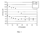
- Two waxes were used to generate random dot patterns. One wax was a polyethylene wax and the other wax was a blend of two polyalphaolefin waxes. The random dots were applied to cover varying area percentages and the 3-psi rub-off data from these tests using the two waxes is shown. The test results are shown in FIG 2.
- Wax A which was somewhat harder than Wax B, was more effective in reducing rub-off.
- Wax A had a melting point of about 62-64°C, and a melting range of about 10°C.
- Wax B had a melting point of about 60-63°C and a melting range of 10°C.
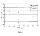
- test results are shown in FIG 3.
- the 0.5 percent wax area coverage data is represented in FIG 3 by the solid diamonds.
- the rub-off values decrease from about 9 down to about 7.3 as the cross-track dots per square inch resolution increases from 50 dpi to 300 dpi.
- the trends for the 1.0 and 2.0 percent areas coverage are similar except that the rub-off values decrease to 6.5 and 4.8 respectively.
- This data suggests that for patterns using random dot patterns, a 300 x 300 dpi resolution print head may not be required since the improvement at a 100 x 300 dpi range print head would appear to provide almost the same rub-off protection as the more expensive 300 x 300 dpi print head.
- a 100 x 300 dpi print head would provide a 3-psi rub-off value of less than 5 while using less wax material. This enables a savings in coating materials as well as in the unit manufacturing costs for the ink jet print head.
- the characters in any font set produced by a printer or digital copier may be used with a wax jet print head to select areas, which may be coated by wax.
- a 300 x 300 or other suitable dot per inch resolution print head may be used once the software (generated for printing or copying) is available for the generation of the instructions to coat only the characters. This would enable the use of less wax while still achieving desirable rub-off protection.
- the test results are shown in FIG 4.
- the data represented in Figure 4 by solid diamonds uses a polyethylene wax, which is applied on top of the toner images and nowhere else.
- a second wax, shown as Wax B was also tested. The amount of wax used is minimized and the rub-off protection is maximized.
- Wax A had a melting point of about 62-64°C, and a melting range of about 10°C.
- Wax B had a melting point of about 60-63°C and a melting range of 10°C.
- the use of the method of the present invention can be implemented by the use of an ink jet printer or the like to coat substrates bearing a toner image as they are produced in a printer or copier machine.
- the prints can be produced photoelectrically, digitally or the like.
- the ink jet dot application system may be implemented as a part of the photocopier or printer machine, or as a stand-alone unit, which may apply rub-off reducing material in a separate step.
Landscapes
- Physics & Mathematics (AREA)
- General Physics & Mathematics (AREA)
- Spectroscopy & Molecular Physics (AREA)
- Chemical & Material Sciences (AREA)
- Chemical Kinetics & Catalysis (AREA)
- Developing Agents For Electrophotography (AREA)
- Ink Jet (AREA)
- Color Electrophotography (AREA)
Applications Claiming Priority (2)
| Application Number | Priority Date | Filing Date | Title |
|---|---|---|---|
| US31087401P | 2001-08-08 | 2001-08-08 | |
| US310874P | 2001-08-08 |
Publications (2)
| Publication Number | Publication Date |
|---|---|
| EP1283449A2 true EP1283449A2 (fr) | 2003-02-12 |
| EP1283449A3 EP1283449A3 (fr) | 2004-03-17 |
Family
ID=23204460
Family Applications (1)
| Application Number | Title | Priority Date | Filing Date |
|---|---|---|---|
| EP02016225A Withdrawn EP1283449A3 (fr) | 2001-08-08 | 2002-07-19 | Méthode pour réduire l'abrasion d'une image de toner utilisant une composition à changement de phase |
Country Status (2)
| Country | Link |
|---|---|
| US (1) | US6775510B2 (fr) |
| EP (1) | EP1283449A3 (fr) |
Cited By (1)
| Publication number | Priority date | Publication date | Assignee | Title |
|---|---|---|---|---|
| US6676255B2 (en) * | 2001-08-08 | 2004-01-13 | Heidelberger Druckmaschinen Ag | Method for reducing rub-off from a toner image using a colored phase change composition |
Families Citing this family (1)
| Publication number | Priority date | Publication date | Assignee | Title |
|---|---|---|---|---|
| US6741828B2 (en) * | 2001-08-08 | 2004-05-25 | Heidelberg Digital L.L.C. | Method for reducing rub-off from a toner image using a phase change composition |
Citations (8)
| Publication number | Priority date | Publication date | Assignee | Title |
|---|---|---|---|---|
| US5922114A (en) | 1996-07-15 | 1999-07-13 | Brother Kogyo Kabushiki Kaisha | Hot-melt ink composition |
| US5958169A (en) | 1993-01-19 | 1999-09-28 | Tektronix, Inc. | Reactive ink compositions and systems |
| US5980621A (en) | 1997-05-15 | 1999-11-09 | Brother Kogyo Kabushiki Kaisha | Hot-melt ink |
| US5994453A (en) | 1996-06-28 | 1999-11-30 | Tektronix, Inc. | Phase change ink formulation containing a combination of a urethane resin, a mixed urethane/urea resin, a mono-amide and a polyethylene wax |
| US6018005A (en) | 1996-06-28 | 2000-01-25 | Tektronix, Inc. | Phase change ink formulation using urethane isocyanate-derived resins and a polyethylene wax |
| US6028138A (en) | 1996-06-28 | 2000-02-22 | Tektronix, Inc. | Phase change ink formulation using urethane isocyanate-derived resins, a polyethylene wax and toughening agent |
| US6037396A (en) | 1997-03-27 | 2000-03-14 | Brother Kogyo Kabushiki Kaisha | Hot-melt ink |
| US6048925A (en) | 1996-06-28 | 2000-04-11 | Xerox Corporation | Urethane isocyanate-derived resins for use in a phase change ink formulation |
Family Cites Families (42)
| Publication number | Priority date | Publication date | Assignee | Title |
|---|---|---|---|---|
| BE755392A (fr) | 1969-08-28 | 1971-02-01 | Teletype Corp | Encre et appareil d'impression electrostatique |
| BE756224A (fr) | 1969-09-23 | 1971-03-01 | Teletype Corp | Encre et appareil d'impression electrostatiques |
| US3984809A (en) | 1975-11-20 | 1976-10-05 | Michael L. Dertouzos | Parallel thermal printer |
| US4250511A (en) | 1979-08-16 | 1981-02-10 | Tektronix, Inc. | Thermal transfer color printer |
| JPS57138960A (en) | 1981-02-20 | 1982-08-27 | Fuji Xerox Co Ltd | Multicolor heat sensitive recorder |
| US4390369A (en) | 1981-12-17 | 1983-06-28 | Exxon Research And Engineering Co. | Natural wax-containing ink jet inks |
| NL8105674A (nl) | 1981-12-16 | 1983-07-18 | Coulter Stork Patents | Werkwijze voor het aanbrengen van een beschermende lichtdoorlatende bekleding op een op een substraat gevormd tonerbeeld. |
| US4484948A (en) | 1981-12-17 | 1984-11-27 | Exxon Research And Engineering Co. | Natural wax-containing ink jet inks |
| US4659383A (en) | 1981-12-17 | 1987-04-21 | Exxon Printing Systems, Inc. | High molecular weight, hot melt impulse ink jet ink |
| US5182572A (en) | 1981-12-17 | 1993-01-26 | Dataproducts Corporation | Demand ink jet utilizing a phase change ink and method of operating |
| US4490731A (en) | 1982-11-22 | 1984-12-25 | Hewlett-Packard Company | Ink dispenser with "frozen" solid ink |
| US4458253A (en) | 1982-12-30 | 1984-07-03 | International Business Machines Corporation | Thermal print apparatus using a thermal transfer ribbon such as a multi-colored one, and a printing method |
| JPS59202876A (ja) | 1983-05-06 | 1984-11-16 | Ricoh Co Ltd | 熱転写式プリンタ |
| US4631557B1 (en) | 1984-10-15 | 1997-12-16 | Data Products Corp | Ink jet employing phase change ink and method of operation |
| US4721635A (en) | 1985-11-08 | 1988-01-26 | Howtek, Inc. | Color printed record and method |
| US4666757A (en) | 1985-11-08 | 1987-05-19 | Howtek, Inc. | Color printed record |
| US4745420A (en) | 1986-07-21 | 1988-05-17 | Dataproducts Corporation | Method and apparatus for controlling the size of dots produced by jetting phase change ink |
| JPS6354476A (ja) | 1986-08-25 | 1988-03-08 | Seiko Epson Corp | 熱溶融性インク |
| US4889560A (en) | 1988-08-03 | 1989-12-26 | Tektronix, Inc. | Phase change ink composition and phase change ink produced therefrom |
| US5151120A (en) | 1989-03-31 | 1992-09-29 | Hewlett-Packard Company | Solid ink compositions for thermal ink-jet printing having improved printing characteristics |
| US5092235A (en) | 1989-05-24 | 1992-03-03 | Tektronix, Inc. | Pressure fixing and developing apparatus |
| US5006170A (en) | 1989-06-22 | 1991-04-09 | Xerox Corporation | Hot melt ink compositions |
| US5185035A (en) | 1990-05-23 | 1993-02-09 | Coates Electrographics Limited | Transparent hot melt jet ink |
| US5389958A (en) | 1992-11-25 | 1995-02-14 | Tektronix, Inc. | Imaging process |
| US5372852A (en) | 1992-11-25 | 1994-12-13 | Tektronix, Inc. | Indirect printing process for applying selective phase change ink compositions to substrates |
| US5339146A (en) * | 1993-04-01 | 1994-08-16 | Eastman Kodak Company | Method and apparatus for providing a toner image having an overcoat |
| US5339148A (en) * | 1993-04-01 | 1994-08-16 | Eastman Kodak Company | Image forming apparatus having recoil fuser |
| EP0629513B1 (fr) | 1993-06-18 | 1997-09-10 | Dai Nippon Printing Co., Ltd. | Feuille à transfert thermique |
| JP2853517B2 (ja) | 1993-06-22 | 1999-02-03 | 富士ゼロックス株式会社 | インクジェット記録方法 |
| US5495270A (en) | 1993-07-30 | 1996-02-27 | Tektronix, Inc. | Method and apparatus for producing dot size modulated ink jet printing |
| US5879790A (en) | 1995-03-06 | 1999-03-09 | Fujicopian Co., Ltd. | Thermal transfer recording medium |
| JP3522909B2 (ja) | 1995-07-21 | 2004-04-26 | 大日本印刷株式会社 | 熱転写シート |
| US5672413A (en) | 1995-09-27 | 1997-09-30 | Rexam Graphics Incorporated | Element and associated process for use with inkjet hot melt inks for thermal image transfer |
| WO1997028968A1 (fr) | 1996-02-08 | 1997-08-14 | Sony Chemicals Corp. | Encre a transfert thermique et ruban encreur a transfert thermique |
| JPH09255905A (ja) | 1996-03-27 | 1997-09-30 | Brother Ind Ltd | 熱溶融性インク |
| US5827918A (en) | 1996-06-28 | 1998-10-27 | Tektronix, Inc. | Phase change ink formulation using urea and urethane isocyanate-derived resins |
| US5830942A (en) | 1996-06-28 | 1998-11-03 | Tektronix, Inc. | Phase change ink formulation using a urethane and urethane/urea isocyanate-derived resins |
| JPH10204358A (ja) | 1996-11-21 | 1998-08-04 | Brother Ind Ltd | ホットメルト型固体インク |
| US5966150A (en) | 1996-11-27 | 1999-10-12 | Tektronix, Inc. | Method to improve solid ink output resolution |
| US5847738A (en) | 1997-07-11 | 1998-12-08 | Eastman Kodak Company | Process for applying protective overcoat on printed media |
| US6015847A (en) | 1998-02-13 | 2000-01-18 | Tektronix, Inc. | Magenta phase change ink formulation containing organic sulfonic acid |
| ATE307031T1 (de) | 1998-05-21 | 2005-11-15 | Canon Kk | Tintenstrahldruckverfahren und tintenstrahldruckgerät |
-
2002
- 2002-07-08 US US10/190,761 patent/US6775510B2/en not_active Expired - Lifetime
- 2002-07-19 EP EP02016225A patent/EP1283449A3/fr not_active Withdrawn
Patent Citations (8)
| Publication number | Priority date | Publication date | Assignee | Title |
|---|---|---|---|---|
| US5958169A (en) | 1993-01-19 | 1999-09-28 | Tektronix, Inc. | Reactive ink compositions and systems |
| US5994453A (en) | 1996-06-28 | 1999-11-30 | Tektronix, Inc. | Phase change ink formulation containing a combination of a urethane resin, a mixed urethane/urea resin, a mono-amide and a polyethylene wax |
| US6018005A (en) | 1996-06-28 | 2000-01-25 | Tektronix, Inc. | Phase change ink formulation using urethane isocyanate-derived resins and a polyethylene wax |
| US6028138A (en) | 1996-06-28 | 2000-02-22 | Tektronix, Inc. | Phase change ink formulation using urethane isocyanate-derived resins, a polyethylene wax and toughening agent |
| US6048925A (en) | 1996-06-28 | 2000-04-11 | Xerox Corporation | Urethane isocyanate-derived resins for use in a phase change ink formulation |
| US5922114A (en) | 1996-07-15 | 1999-07-13 | Brother Kogyo Kabushiki Kaisha | Hot-melt ink composition |
| US6037396A (en) | 1997-03-27 | 2000-03-14 | Brother Kogyo Kabushiki Kaisha | Hot-melt ink |
| US5980621A (en) | 1997-05-15 | 1999-11-09 | Brother Kogyo Kabushiki Kaisha | Hot-melt ink |
Cited By (1)
| Publication number | Priority date | Publication date | Assignee | Title |
|---|---|---|---|---|
| US6676255B2 (en) * | 2001-08-08 | 2004-01-13 | Heidelberger Druckmaschinen Ag | Method for reducing rub-off from a toner image using a colored phase change composition |
Also Published As
| Publication number | Publication date |
|---|---|
| US6775510B2 (en) | 2004-08-10 |
| US20030031486A1 (en) | 2003-02-13 |
| EP1283449A3 (fr) | 2004-03-17 |
Similar Documents
| Publication | Publication Date | Title |
|---|---|---|
| CN110217010B (zh) | 油墨膜构造 | |
| US5614933A (en) | Method and apparatus for controlling phase-change ink-jet print quality factors | |
| US5502476A (en) | Method and apparatus for controlling phase-change ink temperature during a transfer printing process | |
| KR102065802B1 (ko) | 잉크막 구조 | |
| US6540345B1 (en) | Transfer printing process | |
| EP0890447A2 (fr) | Feuille réceptrice d'images pour l'impression par transfert thermique et procédé de sa fabrication | |
| US20120139984A1 (en) | System and method for inkjet printing with a differential halftoned protective overcoat with gloss compensation | |
| US6481840B1 (en) | Automatic document feed of phase change inks | |
| WO2003036392A1 (fr) | Support electrophotographique brillant comprenant un substrat a revetement opaque | |
| US6695502B2 (en) | Method for reducing rub-off from a toner image using a phase change composition on the non-image side of a substrate | |
| US6775510B2 (en) | Method for reducing rub-off from toner or printed images using a phase change composition | |
| EP0850776B1 (fr) | Méthode pour l'impression par jet d'encre utilisant une encre à changement de phase | |
| US6676255B2 (en) | Method for reducing rub-off from a toner image using a colored phase change composition | |
| US6567642B2 (en) | Hybrid thermal transfer roller brush wax applicator for rub-off reduction | |
| US6741828B2 (en) | Method for reducing rub-off from a toner image using a phase change composition | |
| US6692121B2 (en) | Method for reducing rub-off from a toner image using a phase change composition with a rotary brush | |
| US20030096892A1 (en) | Enhanced phase change composition for rub-off reduction | |
| Bohórquez et al. | Laser-comparable inkjet text printing | |
| JP3660464B2 (ja) | インクジェット記録用シート | |
| CN103842914B (zh) | 利用大颗粒的喷墨印刷 | |
| JP4653864B2 (ja) | 記録方法及び記録装置 | |
| US6391466B1 (en) | Thermal transfer recording medium | |
| US6277785B1 (en) | Thermal transfer image-receiving sheet | |
| Briley | Polyester media development for inkjet printers | |
| US5985792A (en) | Apparatus for coating fine particles to produce thermal transfer image receiving sheet method of producing thermal transfer image receiving sheet and thermal transfer image receiving sheet produced thereby |
Legal Events
| Date | Code | Title | Description |
|---|---|---|---|
| PUAI | Public reference made under article 153(3) epc to a published international application that has entered the european phase |
Free format text: ORIGINAL CODE: 0009012 |
|
| AK | Designated contracting states |
Designated state(s): AT BE BG CH CY CZ DE DK EE ES FI FR GB GR IE IT LI LU MC NL PT SE SK TR |
|
| AX | Request for extension of the european patent |
Extension state: AL LT LV MK RO SI |
|
| PUAL | Search report despatched |
Free format text: ORIGINAL CODE: 0009013 |
|
| AK | Designated contracting states |
Kind code of ref document: A3 Designated state(s): AT BE BG CH CY CZ DE DK EE ES FI FR GB GR IE IT LI LU MC NL PT SE SK TR |
|
| AX | Request for extension of the european patent |
Extension state: AL LT LV MK RO SI |
|
| RIC1 | Information provided on ipc code assigned before grant |
Ipc: 7G 03G 8/00 B Ipc: 7G 03G 7/00 A |
|
| RAP1 | Party data changed (applicant data changed or rights of an application transferred) |
Owner name: EASTMAN KODAK COMPANY |
|
| 17P | Request for examination filed |
Effective date: 20040916 |
|
| AKX | Designation fees paid |
Designated state(s): DE FR GB |
|
| 17Q | First examination report despatched |
Effective date: 20050208 |
|
| STAA | Information on the status of an ep patent application or granted ep patent |
Free format text: STATUS: THE APPLICATION IS DEEMED TO BE WITHDRAWN |
|
| 18D | Application deemed to be withdrawn |
Effective date: 20050621 |