EP1283533A2 - Dispositif d'assemblage d'un enroulement sur un noyau - Google Patents
Dispositif d'assemblage d'un enroulement sur un noyau Download PDFInfo
- Publication number
- EP1283533A2 EP1283533A2 EP02078339A EP02078339A EP1283533A2 EP 1283533 A2 EP1283533 A2 EP 1283533A2 EP 02078339 A EP02078339 A EP 02078339A EP 02078339 A EP02078339 A EP 02078339A EP 1283533 A2 EP1283533 A2 EP 1283533A2
- Authority
- EP
- European Patent Office
- Prior art keywords
- core
- coil
- pump
- coils
- branch
- Prior art date
- Legal status (The legal status is an assumption and is not a legal conclusion. Google has not performed a legal analysis and makes no representation as to the accuracy of the status listed.)
- Withdrawn
Links
Images



Classifications
-
- H—ELECTRICITY
- H02—GENERATION; CONVERSION OR DISTRIBUTION OF ELECTRIC POWER
- H02K—DYNAMO-ELECTRIC MACHINES
- H02K5/00—Casings; Enclosures; Supports
- H02K5/04—Casings or enclosures characterised by the shape, form or construction thereof
- H02K5/08—Insulating casings
-
- F—MECHANICAL ENGINEERING; LIGHTING; HEATING; WEAPONS; BLASTING
- F04—POSITIVE - DISPLACEMENT MACHINES FOR LIQUIDS; PUMPS FOR LIQUIDS OR ELASTIC FLUIDS
- F04B—POSITIVE-DISPLACEMENT MACHINES FOR LIQUIDS; PUMPS
- F04B17/00—Pumps characterised by combination with, or adaptation to, specific driving engines or motors
- F04B17/03—Pumps characterised by combination with, or adaptation to, specific driving engines or motors driven by electric motors
- F04B17/04—Pumps characterised by combination with, or adaptation to, specific driving engines or motors driven by electric motors using solenoids
-
- H—ELECTRICITY
- H01—ELECTRIC ELEMENTS
- H01F—MAGNETS; INDUCTANCES; TRANSFORMERS; SELECTION OF MATERIALS FOR THEIR MAGNETIC PROPERTIES
- H01F27/00—Details of transformers or inductances, in general
- H01F27/28—Coils; Windings; Conductive connections
- H01F27/30—Fastening or clamping coils, windings, or parts thereof together; Fastening or mounting coils or windings on core, casing, or other support
- H01F27/306—Fastening or mounting coils or windings on core, casing or other support
-
- H—ELECTRICITY
- H01—ELECTRIC ELEMENTS
- H01F—MAGNETS; INDUCTANCES; TRANSFORMERS; SELECTION OF MATERIALS FOR THEIR MAGNETIC PROPERTIES
- H01F27/00—Details of transformers or inductances, in general
- H01F27/02—Casings
- H01F27/022—Encapsulation
-
- H—ELECTRICITY
- H02—GENERATION; CONVERSION OR DISTRIBUTION OF ELECTRIC POWER
- H02K—DYNAMO-ELECTRIC MACHINES
- H02K15/00—Processes or apparatus specially adapted for manufacturing, assembling, maintaining or repairing of dynamo-electric machines
- H02K15/10—Applying solid insulation to windings, stators or rotors, e.g. applying insulating tapes
Definitions
- This description relates to a utility model patent for assembling a coil on a core, belonging to the field of electromagnetic circuits, in particular vibratory pump circuits, the arrangement of which has been devised in order to improve the performance and useful life of the circuit.
- a vibratory pump includes, among other things, an electromagnetic circuit which consists of a coil and a core and which causes a member to transmit movement to movable components of the pump, responsible for uptaking and pressurising the water.
- an electromagnetic circuit which consists of a coil and a core and which causes a member to transmit movement to movable components of the pump, responsible for uptaking and pressurising the water.
- the aforementioned assemblage consisting of the coil and core, is assembled and housed in a lower section of the body of the pump, connected to an electrical power supply cable which projects outside the hole of the body of the pump and is encapsulated with a resin filling.
- an objective of the arrangement which is the subject of this utility model patent is to provide a way of assembling the coil on the core which overcomes the abovementioned problem.
- Another objective is to provide an assemblage which does not complicate construction and the process for manufacturing the pump.
- Another objective is to provide an assemblage which, despite the abovementioned advantages, does not increase the cost of the pump.
- the core is a "U" type and the respective coils are wound round the parallel branches.
- This assemblage consists essentially of providing two plastic coil protectors, one for each coil wound round the respective branch of the core and comprising essentially: a square-shaped section which is situated around the base of the branch of the core; and rods which project at a right angle from the lower square-shaped section and which are situated in the corners and on the sides of the branches of the core and are intercalated between said corners and sides and the coil, in order to form gaps between the coil and the core, which are also filled with a resin filling.
- the coil protectors isolate the coil from the core, maintaining a uniform distance in all directions, and in view of their geometry they are able to penetrate the resin filling between the coil and the core, in order to lock the whole electrical circuit, thus preventing the wire of the coil from vibrating and shearing and the circuit from burning.
- this assemblage resolves the problem which usually arises, thereby extending the useful life of the electrical circuit and consequently of the pump as a whole.
- the assemblage which is the subject of the present utility model patent applies to the pump and core of an electromagnetic circuit, in particular the electromagnetic circuit of a vibratory pump, comprising essentially, among other things: an electromagnetic circuit 1, responsible for the movement of a member (not illustrated) which transmits movement to movable parts of the pump (not illustrated) responsible for uptaking and pressurising the water; said electromagnetic circuit consists of: a "U" shaped core 2-3 formed by two parallel longitudinal branches 2 and a transverse branch 3 which interconnects the longitudinal branches; and coils 4 wound round the respective parallel branches 2 of the core; said electromagnetic circuit also comprises an electrical power supply cable 5; the body of said pump is formed by, among other things, a lower section (body of the pump) 6, inside which the electromagnetic circuit 1 is housed and assembled and which is equipped with a radial hole for the electric cable to exit; and a resin filling 7 for encapsulating the circuit.
- an electromagnetic circuit 1 responsible for the movement of a member (not illustrated) which transmits movement to movable parts of the pump (not
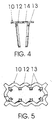
- This arrangement consists of assembling two coil protectors 10, which are intercalated between the respective coils 4 and the corresponding branches of the core 2, defining spaces 11 between the coils and the core, which are filled with the resin filling 7, thus isolating the coils 4 from the core 2-3 and mechanically locking the whole assemblage, which prevents the wires of the coil 4 from vibrating and shearing from occurring over time, thus burning out the circuit.
- Each coil protector 10 comprises essentially: a substantially square-shaped lower section 12 which is assembled around the bottom end of the longitudinal branch 2 of the core, which forms a corner with the transverse branch 3; and corner rods 13 and intermediate rods 14 projecting at right angles from the corners and bigger sides of the square, which are positioned in the corners and on the sides of the branch 2 of the core and are intercalated between the core and the coil 4, thus defining between said branch 2 of the core and the coil 4 the spaces 11; these and the spaces between the coils and between the coils and the wall of the body of the pump and the spaces between the transverse branch 3 of the core and the walls of the body of the pump are filled with the resin filling 7.
- the side of the square 12 which faces downwards to the side of the transverse branch 13 has hollows 14 for the resin to circulate.
- the coil protectors are made of a suitable plastic material.
- the electromagnetic circuit functions in the habitual way, only when it is activated there is no vibration of the coil wires, thereby avoiding the problems which usually arise, as mentioned above.
Landscapes
- Engineering & Computer Science (AREA)
- Power Engineering (AREA)
- Mechanical Engineering (AREA)
- General Engineering & Computer Science (AREA)
- Reciprocating, Oscillating Or Vibrating Motors (AREA)
- Electromagnets (AREA)
- Details Of Reciprocating Pumps (AREA)
Applications Claiming Priority (2)
| Application Number | Priority Date | Filing Date | Title |
|---|---|---|---|
| BRMU8102102-0U BR8102102Y1 (pt) | 2001-08-09 | 2001-08-09 | disposição na montagem da bobina no núcleo. |
| BR8102102 | 2001-08-09 |
Publications (2)
| Publication Number | Publication Date |
|---|---|
| EP1283533A2 true EP1283533A2 (fr) | 2003-02-12 |
| EP1283533A3 EP1283533A3 (fr) | 2004-02-04 |
Family
ID=4027280
Family Applications (1)
| Application Number | Title | Priority Date | Filing Date |
|---|---|---|---|
| EP02078339A Withdrawn EP1283533A3 (fr) | 2001-08-09 | 2002-08-09 | Dispositif d'assemblage d'un enroulement sur un noyau |
Country Status (3)
| Country | Link |
|---|---|
| EP (1) | EP1283533A3 (fr) |
| BR (1) | BR8102102Y1 (fr) |
| IL (1) | IL151140A0 (fr) |
Family Cites Families (5)
| Publication number | Priority date | Publication date | Assignee | Title |
|---|---|---|---|---|
| US3525966A (en) * | 1968-07-24 | 1970-08-25 | Square D Co | Encapsulated coil and method of making same and spacer for use during encapsulation |
| US5100311A (en) * | 1990-09-21 | 1992-03-31 | Dana Corporation | Coil locator for mold encapsulation |
| DE4037994C1 (fr) * | 1990-11-29 | 1992-03-05 | Licentia Patent-Verwaltungs-Gmbh, 6000 Frankfurt, De | |
| US5497136A (en) * | 1992-11-30 | 1996-03-05 | Dana Corporation | Locating ring for encapsulating a coil |
| BR9903092C1 (pt) * | 1999-06-22 | 2004-10-19 | Anauger Motores Ind Ltd | Aperfeiçoamento em bomba vibratória |
-
2001
- 2001-08-09 BR BRMU8102102-0U patent/BR8102102Y1/pt not_active IP Right Cessation
-
2002
- 2002-08-08 IL IL15114002A patent/IL151140A0/xx unknown
- 2002-08-09 EP EP02078339A patent/EP1283533A3/fr not_active Withdrawn
Also Published As
| Publication number | Publication date |
|---|---|
| BR8102102Y1 (pt) | 2009-05-05 |
| IL151140A0 (en) | 2003-04-10 |
| EP1283533A3 (fr) | 2004-02-04 |
| BR8102102U (pt) | 2003-07-08 |
Similar Documents
| Publication | Publication Date | Title |
|---|---|---|
| CN103140685A (zh) | 电动泵 | |
| US20090277682A1 (en) | Protective structure for a circuit board and method for fabricating the same | |
| CA2542260A1 (fr) | Bobine d'antenne et antenne | |
| KR20120018781A (ko) | 파워 모듈 | |
| EP2936507B1 (fr) | Ensemble bobine de charge inductive | |
| JP6768090B2 (ja) | 電子ユニット及び電子ユニットを形成する方法 | |
| WO2016180588A1 (fr) | Stator pour une machine électrique doté d'un dispositif d'interconnexion encapsulé et machine électrique équipée d'un tel stator | |
| JP2020178342A (ja) | アンテナ | |
| EP1283533A2 (fr) | Dispositif d'assemblage d'un enroulement sur un noyau | |
| EP1739814A3 (fr) | Ensemble inducteur encapsulé et procédé d'encapsulage d'un ensemble inducteur | |
| US20150311763A1 (en) | Two-component isolation of bl stators | |
| KR20190131253A (ko) | 차단기의 극 부품 조립체 | |
| KR102005605B1 (ko) | 차량 부품 지지체 및 그 제조 방법 | |
| US11949156B2 (en) | Long range low frequency antenna | |
| WO2006001216A1 (fr) | Rotor à rotation du côté extérieur pour les machines dynamoélectriques | |
| EP3404768B1 (fr) | Antenne triaxiale à profil bas | |
| JP6649615B2 (ja) | コイル装置 | |
| KR102902686B1 (ko) | 에너지 하베스팅 블록 | |
| AU2008330276B2 (en) | Aluminum antenna coil | |
| KR20140148237A (ko) | 블록완구 | |
| JP6649616B2 (ja) | コイル装置 | |
| JP6334176B2 (ja) | 抵抗器 | |
| JP2001165239A (ja) | ダンパーユニット | |
| KR100309457B1 (ko) | 마그네틱 센서 및 그 제조방법 | |
| JP2004076586A (ja) | 鉄心へのコイル取付配置 |
Legal Events
| Date | Code | Title | Description |
|---|---|---|---|
| PUAI | Public reference made under article 153(3) epc to a published international application that has entered the european phase |
Free format text: ORIGINAL CODE: 0009012 |
|
| AK | Designated contracting states |
Designated state(s): AT BE BG CH CY CZ DE DK EE ES FI FR GB GR IE IT LI LU MC NL PT SE SK TR |
|
| AX | Request for extension of the european patent |
Extension state: AL LT LV MK RO SI |
|
| PUAL | Search report despatched |
Free format text: ORIGINAL CODE: 0009013 |
|
| RIC1 | Information provided on ipc code assigned before grant |
Ipc: 7H 01F 27/06 B Ipc: 7F 04B 17/04 B Ipc: 7H 01F 27/30 A |
|
| AK | Designated contracting states |
Kind code of ref document: A3 Designated state(s): AT BE BG CH CY CZ DE DK EE ES FI FR GB GR IE IT LI LU MC NL PT SE SK TR |
|
| AX | Request for extension of the european patent |
Extension state: AL LT LV MK RO SI |
|
| AKX | Designation fees paid | ||
| REG | Reference to a national code |
Ref country code: DE Ref legal event code: 8566 |
|
| STAA | Information on the status of an ep patent application or granted ep patent |
Free format text: STATUS: THE APPLICATION IS DEEMED TO BE WITHDRAWN |
|
| 18D | Application deemed to be withdrawn |
Effective date: 20040805 |