EP1283535A2 - Handsteuerungseinrichtung für ein ferngesteuertes Fahrzeug - Google Patents
Handsteuerungseinrichtung für ein ferngesteuertes Fahrzeug Download PDFInfo
- Publication number
- EP1283535A2 EP1283535A2 EP02255523A EP02255523A EP1283535A2 EP 1283535 A2 EP1283535 A2 EP 1283535A2 EP 02255523 A EP02255523 A EP 02255523A EP 02255523 A EP02255523 A EP 02255523A EP 1283535 A2 EP1283535 A2 EP 1283535A2
- Authority
- EP
- European Patent Office
- Prior art keywords
- controller
- hand
- fish
- hand controller
- control
- Prior art date
- Legal status (The legal status is an assumption and is not a legal conclusion. Google has not performed a legal analysis and makes no representation as to the accuracy of the status listed.)
- Withdrawn
Links
Images


Classifications
-
- H—ELECTRICITY
- H01—ELECTRIC ELEMENTS
- H01H—ELECTRIC SWITCHES; RELAYS; SELECTORS; EMERGENCY PROTECTIVE DEVICES
- H01H9/00—Details of switching devices, not covered by groups H01H1/00 - H01H7/00
- H01H9/02—Bases, casings, or covers
- H01H9/0214—Hand-held casings
- H01H9/0235—Hand-held casings specially adapted for remote control, e.g. of audio or video apparatus
-
- H—ELECTRICITY
- H01—ELECTRIC ELEMENTS
- H01H—ELECTRIC SWITCHES; RELAYS; SELECTORS; EMERGENCY PROTECTIVE DEVICES
- H01H9/00—Details of switching devices, not covered by groups H01H1/00 - H01H7/00
- H01H9/02—Bases, casings, or covers
- H01H9/0214—Hand-held casings
-
- H—ELECTRICITY
- H01—ELECTRIC ELEMENTS
- H01H—ELECTRIC SWITCHES; RELAYS; SELECTORS; EMERGENCY PROTECTIVE DEVICES
- H01H9/00—Details of switching devices, not covered by groups H01H1/00 - H01H7/00
- H01H9/02—Bases, casings, or covers
- H01H9/0214—Hand-held casings
- H01H9/0235—Hand-held casings specially adapted for remote control, e.g. of audio or video apparatus
- H01H2009/0257—Multisided remote control, comprising control or display elements on at least two sides, e.g. front and back surface
-
- H—ELECTRICITY
- H01—ELECTRIC ELEMENTS
- H01H—ELECTRIC SWITCHES; RELAYS; SELECTORS; EMERGENCY PROTECTIVE DEVICES
- H01H2221/00—Actuators
- H01H2221/008—Actuators other then push button
- H01H2221/012—Joy stick type
-
- H—ELECTRICITY
- H01—ELECTRIC ELEMENTS
- H01H—ELECTRIC SWITCHES; RELAYS; SELECTORS; EMERGENCY PROTECTIVE DEVICES
- H01H25/00—Switches with compound movement of handle or other operating part
- H01H25/04—Operating part movable angularly in more than one plane, e.g. joystick
Definitions
- the present invention relates to remote operated vehicles (ROVs), and in particular to hand controllers for ROVs.
- ROVs remote operated vehicles
- ROVs are used in exploration of underwater environments.
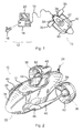
- FIGS 1 to 3 show an ROV which comprises an underwater unit or “fish” 10, and a surface control unit or “topside” 12. Joining the fish 10 and topside 12 there is a communications cable or "umbilical cable" 14.
- the topside 12 comprises a wireless hand controller 16 and a computer unit 18 with a monitor 20.
- the wireless hand controller allows the operator to be free to move anywhere within the range of the wireless link.
- the topside's computer unit 18 there is a receiver which takes signals from the hand-controller and processes them prior to conveying instructions to the fish's control components via the cable 14.
- the hand controller 16 includes an RF transceiver to communicate with the computer unit 18.
- the monitor 20 or view screen is provided for the computer unit 18 for displaying images provided by cameras mounted in the fish 10.
- the fish 10 comprises a main body 11 having a front end 22, a rear end 24, left and right sides 26,28, and top and bottom sides 30,32.
- the main body 11 contains a water and pressure resistant vessel 227 housing a processing unit for controlling components of the fish 10 as well as a battery 52 which is the main power source for driving the thrusters and other equipment on the fish 10.
- a transparent dome 34 in which is mounted a video camera 225.
- the camera 225 is placed inside the pressure vessel 227 which is generally made of a transparent material with a transparent frontal dome 229.
- An additional transparent outer dome 231 is removably fitted in front of the frontal dome 229.
- twin thrusters 36 Towards the rear end 24, on both the left and right sides 26,28 of the fish 10 there are provided twin thrusters 36.
- the thrusters 36 are each mounted to main body 11 of the fish 10 on two arms 38,40, one of which extends substantially sideways from the rear end 24 of the main body 11, and the other of which extends outwardly and then sweeps back rearwardly from the front end 22 of the fish 10 to the center of the thruster 36.
- the twin thrusters 36 are independently drivable to allow forward, reverse and rotational (about a vertical axis by oppositely driving the two thrusters 36) driving force to be given to the fish 10.
- the side thrusters 36 each comprise a propeller arranged in a Kort 92
- a third thruster 42 is provided inside the main body 11 of the fish within a vent 44 extending through the main body 11 from the top side 30 to the bottom side 32.
- the third thruster 42 provides a driving force to raise or lower the depth of the fish in water.
- Lights 46 are provided on each second arm 40 holding the side thrusters. The lights provide forward illumination to assist the front facing camera to pick up an image under water.
- a second camera is provided within a periscope portion 48 extending upwards from a rearward portion of the vent 44 on the top side 30 of the main body 11.
- a small front-facing window 50 is provided for the second camera to view through.
- FIGS. 4A and 4B show the hand controller 16 in more detail.
- the hand controller 16 is powered by a battery 272.
- An RF transmitter 288 is provided to send control signals to the computer unit 18.
- Windows 289 for viewing information on an LCD 291 are provided on the handset 16 for displaying information to the operator, such as handset battery life and indications of the signals being sent.
- a zebra strip 293 interconnects the LCD 291 to a PCB.
- Splash-proof elastomer seals 274 and rubber gaiters 276 are provided to protect various components as illustrated.
- the hand controller 16 comprises buttons 264 and a joystick 266 so that a user can use the hand controller 16 to provide instructions to the computer unit 18 for controlling the fish 10.
- a trigger 268 is also provided to operate a potentiometer 270.
- the trigger 268 serves to control fish linear speed in the forward direction (forward surge). Fish steering in the left and right direction (yaw) is controlled by left and right motion of the joystick 266. Pressing the button 264 arranged to the left of joystick moves the fish in reverse (rearward surge). No yaw control is implemented while reversing, rearward surge being used exclusively as a "get out of trouble" motion, not for general flying of the fish. Forward/backward actuation of the joystick 266 causes up and down motion of the fish (vertical thruster control) to dive up and down (heave).
- left-right joystick motion controls yaw
- back/forward joystick motion controls heave
- the trigger controls forward surge
- the button beside the joystick provides rearward surge.
- a hand controller for an ROV with left and right side thrusters and a vertical thruster comprising: a handle portion shaped for gripping between the fingers and palm of either a left or a right hand; a first controller mounted for thumb actuation by the gripping left or right hand and configured to provide control signals for a left thruster and a right thruster of the ROV, thereby to control surge and yaw; and a second controller mounted for index finger actuation by the gripping left or right hand and configured to provide control signals for a vertical thruster of the ROV, thereby to control heave.
- a user can grip the hand controller between the middle, ring and little fingers and the palm of one hand.
- the thumb can be stretched out resting on the upper surface of the hand controller immediately in front of the first controller which may be a joystick.
- the user can thus actuate the first controller without changing grip on the hand controller through movement of the thumb.
- the index finger of the user rests on the second controller and is able to control surge and yaw, i.e. vertical motion, for example with suitable buttons.
- surge and yaw i.e. vertical motion, for example with suitable buttons.
- the vertical control of the fish motion can therefore also be performed without any change of grip of the user.
- the hand controller thus allows control of all three degrees of freedom of a fish (surge, yaw and heave) to be performed intuitively with single handed operation.
- the second controller may comprise first and second actuation elements for initiating up and down heave motion.
- the hand controller preferably comprises a wireless transmitter for transmitting the control signals to a control unit.
- a cable connection between the hand controller and the topside computer unit could be provided.
- the first controller is a joystick.
- a trackball or other multidimensional manually actuatable input device could be used.
- the hand controller may further comprise a camera controller mounted for actuation by another hand and configured to provide further control signals for panning and tilting a camera in the ROV.
- the hand controller may also further comprise a light controller mounted for actuation by another hand and configured to provide further control signals for switching on and off at least one light in the ROV.
- a topside comprising a hand controller according to the first aspect of the invention and a computer unit.
- an ROV comprising a topside according to the second aspect of the invention, a fish and an umbilical cable for connecting the topside and fish.
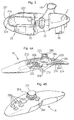
- FIGS 5A and 5B show a hand controller 16 according to an embodiment of the invention.
- the hand controller comprises a handle portion 345 and a distal portion 355 having an upper surface visible to a user gripping the handle portion 345 between the fingers and palm of either the user's left hand or right hand.
- the hand controller is switched on and off with a button 346 arranged for thumb actuation. Holding down the button 346 for three seconds toggles the hand controller on or off, similar to a mobile phone.
- An array of three light emitting diodes (LEDs) 343 immediately under the on/off button 346 are illuminated according to the charge state of the internal batteries housed inside the hand controller.
- LEDs light emitting diodes
- Figure 5B illustrates the hand controller 16 in side view.
- An upstanding analog thumb joystick 340 is evident extending from the upper surface of the hand controller.
- the joystick is mounted for thumb actuation by a left or right hand gripping the handle portion 345.
- the function of the joystick is for control of the side thrusters 36 of the fish. More particularly, the thumb joystick 340 provides control signals for controlling the surge (forward/back motion) and yaw (left and right motion) of the fish 10.
- the joystick is a two-axis (X-Y) potentiometer joystick. Positioned to the left and right side of the thumb joystick 340 are digital speed buttons 342 and 344 respectively which give direct control of the maximum power limit for the thrusters.
- the button 342 positioned to the left of the joystick reduces the maximum power applicable to the thrusters.
- the button 344 position to the right of the joystick 340 increases the maximum power limit applicable to the thrusters.
- the buttons 342 and 344 thus, for example, define a maximum linear speed of the fish (surge) when the joystick 340 is pushed furthest forward, and also define maximum angular speed of the fish (yaw) when the joystick 340 is pushed to one of its diagonal limits. This is useful for changing between sensitive low speed control (e.g. at a destination site) and high speed travel (e.g. from topside deployment area to destination site), and also for battery conservation.
- the maximum power limit control provided by the buttons 342 and 344 is a progressive control implemented by a time ramp in software in the topside computer unit 18.
- the status of the maximum power or speed settings currently set are given to the user through the monitor 20 of the topside computer unit 18.
- Control of the fish 10 in the vertical direction (heave) is provided by a further controller 348 positioned in a trigger position on the underside of the hand controller 16.
- the trigger controller 348 is mounted for index finger actuation by a left or right hand gripping the hand controller 16 by the handle portion 345.
- the trigger controller 348 comprises two digital buttons 350 and 352 for actuating upward and downward motion of the fish respectively.
- Control software on the topside computer unit 18 applies a time ramp on reception of a signal from one of the buttons 350 and 352, thus controlling the linear speed of the fish in the vertical direction. Heave control is effected through the vertical thruster 42 arranged in the vent 44 in the main body 11 of the fish 10.
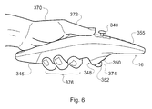
- Figure 6 shows the hand controller 16 during use.
- the left hand 370 of a user is gripping the hand controller 16 between the middle, ring and little fingers 376 and the palm 371.
- the thumb 372 is stretched out resting on the upper surface of the hand controller immediately in front of the joystick 340.
- the user can actuate the joystick 340 without changing grip on the hand controller through movement of the thumb 372.
- the index finger 374 of the user is resting on the trigger controller 348 and is able to actuate either the up drive button 350 or the down drive button 352.
- this actuation can be performed without any change of grip of the user.
- the hand controller 16 thus allows control of all three degrees of freedom of the fish (surge, yaw and heave) to be performed almost intuitively with a single hand operation.
- the hand controller can be used equally well with the left hand or the right hand.
- buttons are visible in the front portion of the upper surface of the hand controller.
- a group of buttons 364 is mounted towards the front nose of the hand controller. The buttons 364 provide control for the camera alignment of the camera 225 mounted in the fish behind the double-layer dome 34. The button group 364 is provided to control the pan and tilt mechanism of the body mounted camera 225.
- the button group 364 comprises a tilt-up button 367, a tilt-down button 365, a pan-left button 368 and a pan-right button 366 arranged in a star configuration with the buttons at North, South, East and West positions, as well as a pan-and-tilt center button 369 which is arranged centrally between the buttons 365-368 recessed from the surface of the pan controller.
- the buttons 365-368 control only the direction of movement of the camera mounting mechanism, not its speed.
- a constant-speed closed-loop control is implemented in the fish's control electronics. When all buttons are released, the camera holds the last position. Pressing two adjacent buttons, for example buttons 366 and 367, produces a diagonal movement of the camera. Actuation of the recessed button 369 in the middle of the four pan and tilt buttons serves to re-center the pan and tilt view of the camera 225 so that the camera is facing straight ahead with its optical axis aligned with the main body 11 of the fish.
- buttons 354, 356, 358 and 360 provide various graphics functions on the topside monitor 20.
- the camera control buttons 364 and the other control buttons 354-362 are easily controlled by the thumb or index finger of the user's other hand, that is the hand of the user which is not gripping the handle portion 345.
- the various control signals are transmitted to the topside computer unit 18 with a radio frequency (RF) link which is now described in more detail.
- RF radio frequency
- a non-wireless communication link could be established using a cable. This alternative is not preferred.
- Figure 7 shows block schematic hardware drawings of the hand controller 16 and the topside computer unit 18.
- Figure 8 is a block schematic hardware drawing of the fish control electronics.
- the hand controller uses wireless communication in air in the form of radio frequency (RF) transmissions. This is accomplished by a RF transmitter module 380, which is paired at the topside computer unit 18 by a RF receiver module 382. Both modules use a 433.92 MHz carrier.
- the data rate is 5KHz, and the packet transfer rate is about 16.6Hz (or every 60ms). Packet length is approximately 20ms.
- a packet When a packet is received by the topside receiver 382, it is encoded in standard RS-232 via a buffer 384 and forwarded at 9600 bauds data rate via a serial link 386 to the topside control computer 388. Packets are composed of 11 bytes of information from the hand controller and hence have a packet length of approximately 11ms, transferred at a rate of the order of 14Hz.
- Communication from the fish 10 is performed through the umbilical cable 14.
- the video and audio content of the fish signals are collected by a 32MHz video receiver 390 and a 5.5MHz hydrophone receiver 392 respectively.
- the video picture from one or both of the fish cameras and the audio signal from the hydrophone are transmitted from the fish as analog FM signals on 32MHz and 5.5MHz carriers respectively.
- Control signals from the fish are received by a 6.5MHz RF data receiver 394 and supplied via buffers 396 and 398, and a serial link 400 to the topside control computer 388.
- Control signals for the fish generated by the topside control computer responsive to the hand controller control signal inputs, are output to the cable 14 through a downlink comprising a serial link 402, data buffer 404 and 6.0MHz RF data transmitter 406.
- FIG. 8 is now referred to to describe the fish internal data system which is housed in the main pressure hull 227 of the fish.
- the control electronics in the pressure hull is powered by the batteries in the fish.
- Video and audio data from the fish hydrophone are transmitted to the topside control unit 18 through the umbilical cable 14 using a 32MHz video system transmitter 410 and a 5.5MHz hydrophone transmitter 412 respectively.
- Data received from the topside unit RF data transmitter 406 is received by a corresponding 6.0 MHz RF data receiver 414 connected to subcontrollers 416 for interpreting and outputting corresponding control signals for the video system control (e.g.
- Motor and light control is effected through the power pack via a control unit 418 accessed from the RF data receiver 414 by a connection leading through a power pack data coupler 420.
- the power pack data coupler allows the 'Downlink' data stream to be transferred to the power pack with a non-contact interface. This can either be done by optical means or another stage of RF FSK modulation using carriers in the 200-400kHz range.
- Telemetry signals relating to the battery status and thruster motor status is sent from a telemetry unit 422 in the power pack through an 'Uplink' power pack data coupler 424 to a 6.5MHz RF data transmitter 426 matched to the topside control unit RF data receiver 394.
- the 'Uplink' data coupler 424 is implemented similarly to the 'Downlink' data coupler 420.
- the power pack telemetry unit 422 sends cell voltage, power pack temperature and motor speed data.
- Telemetry signals from option units are supplied to the transmitter through an options telemetry unit 428.
- a pressure reading from a pressure sensor in the fish pressure hull 277 is also supplied to the RF data transmitter 426 from a hull telemetry unit 430.
- the main pressure hull telemetry comprises compass bearing, depth, temperature and immersion data. If GPS is fitted, the main pressure hull will also send longitude and latitude position data. If inertial guidance, e.g. a fiber gyroscope, is fitted, the main pressure hull will also send fish travel speed and direction information.
- the RF data transmitter 426 transmits to the RF data receiver 394 through the umbilical cable 14.
- the fish internal data transfer is based on the 'Inbus' protocol.
- This protocol uses 0-5V pulse widths to indicate a '1' or '0'.
- a 200us pulse indicates a '1' and a 100us or 300us pulse indicates a '0'.
- the data stream can be made to average 200us pulses and therefore it is possible to a.c. couple the bit stream.
- the bit stream is formed into packets.
- the packet structure contains synchronization and address bytes and also error checking.
- a basic 'Inbus' packet is 11 bytes long and contains 7 bytes of data. Thus, an 'Inbus' packet length is approximately 18ms.
- RS232 In order to facilitate communication with the topside single board computer 388 all 'Inbus' data streams are converted to RS232.
- the data from the various 'Inbus' data streams are buffered to absorb the asynchronous nature of the various parts of the system.
- One central processor collects and formats this data into RS232 data packets (also with error checking), which are sent and received from the single board control computer 388.
- Data to and from the fish (main pressure hull and power pack) are sent and received through COM1 and hand controller data is send to COM2.
- the RS232 baud rate is arbitrary and at the moment 9.6 kbaud is used.
- Data flow in the system can be divided in to two directions - 'Downlink' and 'Uplink'.
- the 'Downlink' data packet contains tele-command data for control of motors, lights, cameras, pan-and-tilt, strobe light and cable eject. All data necessary for these functions is included in one 'Inbus' packet which is send repeatedly from the topside every ⁇ 20ms.
- Each of the separate functions listed above listen to the same 'Downlink' data stream and extract the data, which is salient to them. It is possible to extend the capability of the 'Downlink' data stream to include more data (e.g. for control of option mounts). This can be done in two ways. Either by using the address code of the 'Inbus' packet to target data to another part of the system or by extended the number of data bytes carried by the 'Downlink' packet.
- the 'Uplink' data stream Independent of the 'Downlink' is the 'Uplink' data stream, which contains telemetry data from the onboard battery of the fish 10.
- the 'Uplink' differs from the 'Downlink' data stream in that a number of different 'Inbus' packets are sent consecutively.
- the 'Uplink' data stream is initiated by the 'Inbus' packet from the power pack.
- the main pressure hull electronics listens to the 'Uplink' data stream and, after the power pack packet has been sent, inserts its own telemetry 'Inbus' packet.
- the hand controller also uses the 'Inbus' protocol. As stated above, the state of the various controls on the hand controller are measured and an 'Inbus' packet is sent every ⁇ 60ms. This data stream is FSK modulated on to a 433.92MHz carrier which is transmitted through free space using a standard pre-approved transmitter module. (Provision has also been made to use other types and frequencies of pre-approved transmitter modules.) The data stream is received by the corresponding receiver module, and the 'Inbus' data stream is received and buffered before being sent to the single board control computer 388
Landscapes
- Engineering & Computer Science (AREA)
- Multimedia (AREA)
- Selective Calling Equipment (AREA)
- Mechanical Control Devices (AREA)
Applications Claiming Priority (2)
| Application Number | Priority Date | Filing Date | Title |
|---|---|---|---|
| US928258 | 2001-08-10 | ||
| US09/928,258 US6662742B2 (en) | 2000-02-10 | 2001-08-10 | Remote operated vehicles |
Publications (2)
| Publication Number | Publication Date |
|---|---|
| EP1283535A2 true EP1283535A2 (de) | 2003-02-12 |
| EP1283535A3 EP1283535A3 (de) | 2004-11-17 |
Family
ID=25455970
Family Applications (1)
| Application Number | Title | Priority Date | Filing Date |
|---|---|---|---|
| EP02255523A Withdrawn EP1283535A3 (de) | 2001-08-10 | 2002-08-07 | Handsteuerungseinrichtung für ein ferngesteuertes Fahrzeug |
Country Status (1)
| Country | Link |
|---|---|
| EP (1) | EP1283535A3 (de) |
Cited By (9)
| Publication number | Priority date | Publication date | Assignee | Title |
|---|---|---|---|---|
| EP1507184A2 (de) | 2003-08-11 | 2005-02-16 | Manitou Bf | Vorrichtung zum Steuern durch Wechselwirkung mit der Hand einer Bedienungsperson |
| GB2415522A (en) * | 2004-05-29 | 2005-12-28 | Sauer Danfoss Aps | Joystick control with wireless signal transmission and wireless energy supply |
| WO2011049470A1 (en) * | 2009-10-20 | 2011-04-28 | Cwf Hamilton & Co Limited | Manoeuvring and control device and system |
| CN103425110A (zh) * | 2013-08-19 | 2013-12-04 | 青岛远创机器人自动化有限公司 | 一种浅水观察级流线型小型水下机器人控制系统 |
| CN103439894A (zh) * | 2013-08-19 | 2013-12-11 | 青岛远创机器人自动化有限公司 | 一种浅小型水下机器人甲板控制系统 |
| FR3003678A1 (fr) * | 2013-03-20 | 2014-09-26 | Bigben Interactive Sa | Telecommande ergonomique. |
| CN105460190A (zh) * | 2015-12-01 | 2016-04-06 | 黑龙江科技大学 | 能够电脑遥控的仿生欠驱动水下机器人及控制方法 |
| EP1972363B2 (de) † | 2005-08-22 | 2019-08-21 | Nintendo Co., Ltd. | Spielsteuerungsgerät |
| DE102013008891B4 (de) * | 2013-05-27 | 2020-03-19 | Fm Marketing Gmbh | Fernsteuerung |
Family Cites Families (6)
| Publication number | Priority date | Publication date | Assignee | Title |
|---|---|---|---|---|
| US3521589A (en) * | 1969-02-19 | 1970-07-21 | Frederick O Kemp | Underwater vessel |
| GB2163114B (en) * | 1984-07-02 | 1987-11-25 | Offshore Syst Eng Osel | Improvements in or relating to underwater vehicles |
| US6069614A (en) * | 1995-05-04 | 2000-05-30 | Singhal; Tara C | Man machine interface via display peripheral |
| US5670988A (en) * | 1995-09-05 | 1997-09-23 | Interlink Electronics, Inc. | Trigger operated electronic device |
| TW356730U (en) * | 1997-06-14 | 1999-04-21 | Top Game & Company Ltd | Operation apparatus for game machine |
| FR2796917B1 (fr) * | 1999-07-29 | 2001-10-05 | Andre Schaer | Plate-forme mobile telecommandee apte a evoluer dans un milieu tel que l'eau ou l'air |
-
2002
- 2002-08-07 EP EP02255523A patent/EP1283535A3/de not_active Withdrawn
Cited By (15)
| Publication number | Priority date | Publication date | Assignee | Title |
|---|---|---|---|---|
| EP1507184A2 (de) | 2003-08-11 | 2005-02-16 | Manitou Bf | Vorrichtung zum Steuern durch Wechselwirkung mit der Hand einer Bedienungsperson |
| FR2858861A1 (fr) | 2003-08-11 | 2005-02-18 | Manitou Bf | Dispositif de commande par interaction avec la main d'un operateur |
| GB2415522A (en) * | 2004-05-29 | 2005-12-28 | Sauer Danfoss Aps | Joystick control with wireless signal transmission and wireless energy supply |
| GB2415522B (en) * | 2004-05-29 | 2008-05-21 | Sauer Danfoss Aps | Joystick arrangement |
| EP1972363B2 (de) † | 2005-08-22 | 2019-08-21 | Nintendo Co., Ltd. | Spielsteuerungsgerät |
| WO2011049470A1 (en) * | 2009-10-20 | 2011-04-28 | Cwf Hamilton & Co Limited | Manoeuvring and control device and system |
| EP2797063A3 (de) * | 2013-03-20 | 2015-04-01 | Bigben Interactive SA | Ergonomische Fernsteuerung |
| FR3003678A1 (fr) * | 2013-03-20 | 2014-09-26 | Bigben Interactive Sa | Telecommande ergonomique. |
| EP2797063A2 (de) | 2013-03-20 | 2014-10-29 | Bigben Interactive SA | Ergonomische Fernsteuerung |
| DE102013008891B4 (de) * | 2013-05-27 | 2020-03-19 | Fm Marketing Gmbh | Fernsteuerung |
| CN103439894A (zh) * | 2013-08-19 | 2013-12-11 | 青岛远创机器人自动化有限公司 | 一种浅小型水下机器人甲板控制系统 |
| CN103425110B (zh) * | 2013-08-19 | 2016-05-11 | 青岛远创机器人自动化有限公司 | 一种浅水观察级流线型小型水下机器人控制系统 |
| CN103439894B (zh) * | 2013-08-19 | 2016-10-05 | 青岛远创机器人自动化有限公司 | 一种浅小型水下机器人甲板控制系统 |
| CN103425110A (zh) * | 2013-08-19 | 2013-12-04 | 青岛远创机器人自动化有限公司 | 一种浅水观察级流线型小型水下机器人控制系统 |
| CN105460190A (zh) * | 2015-12-01 | 2016-04-06 | 黑龙江科技大学 | 能够电脑遥控的仿生欠驱动水下机器人及控制方法 |
Also Published As
| Publication number | Publication date |
|---|---|
| EP1283535A3 (de) | 2004-11-17 |
Similar Documents
| Publication | Publication Date | Title |
|---|---|---|
| US6986320B2 (en) | Remote operated vehicles | |
| CN107340777B (zh) | 一种水下无人船控制系统及方法 | |
| US11046429B2 (en) | Head mounted display and method for maneuvering vehicle | |
| EP1283535A2 (de) | Handsteuerungseinrichtung für ein ferngesteuertes Fahrzeug | |
| US7818910B2 (en) | Weapon integrated controller | |
| RU2650493C2 (ru) | Система распределения видео в реальном времени | |
| CN106781371A (zh) | 一种水下无人船的通信系统 | |
| WO2017140096A1 (zh) | 一种无人船及系统 | |
| CN105988479A (zh) | 用于优化远程控制装置相对于飞行或旋转无人机的取向的方法 | |
| US7253398B2 (en) | Sensor system with improved operator input devices | |
| CN206601787U (zh) | 一种水下无人船的通信系统 | |
| US20110031044A1 (en) | Robotic platform & methods for overcoming obstacles | |
| WO2019000855A1 (zh) | 一种半潜式小型无人艇集成控制系统 | |
| CN207283716U (zh) | 可切换摄像头的无人机及无人机控制系统 | |
| CN109963117B (zh) | 一种水下航行器的自主跟踪拍摄系统 | |
| US12470814B2 (en) | Systems, devices, and methods supporting multiple photography modes with a control device | |
| CN109462824A (zh) | 广播通信网络标识符的方法、连接至通信网络的方法、计算机程序、宿留介质和移动终端 | |
| JP2001209426A (ja) | 移動体制御装置 | |
| JP2003312592A (ja) | 遠隔操縦システム | |
| EP1308829A2 (de) | Graphische Benutzerschnittstelle für ein ferngesteuertes Fahrzeug | |
| JP7820628B2 (ja) | 水上浮遊体、水上浮遊体の制御方法及び制御装置 | |
| KR102101747B1 (ko) | 물놀이용 보드 | |
| CN116946327A (zh) | 一种小型水面智能救援u型艇 | |
| JP2019064373A (ja) | 無人無索潜水機システム | |
| JP2019058141A (ja) | 釣り情報提供システム |
Legal Events
| Date | Code | Title | Description |
|---|---|---|---|
| PUAI | Public reference made under article 153(3) epc to a published international application that has entered the european phase |
Free format text: ORIGINAL CODE: 0009012 |
|
| AK | Designated contracting states |
Designated state(s): AT BE BG CH CY CZ DE DK EE ES FI FR GB GR IE IT LI LU MC NL PT SE SK TR |
|
| AX | Request for extension of the european patent |
Extension state: AL LT LV MK RO SI |
|
| PUAL | Search report despatched |
Free format text: ORIGINAL CODE: 0009013 |
|
| AK | Designated contracting states |
Kind code of ref document: A3 Designated state(s): AT BE BG CH CY CZ DE DK EE ES FI FR GB GR IE IT LI LU MC NL PT SE SK TR |
|
| AX | Request for extension of the european patent |
Extension state: AL LT LV MK RO SI |
|
| RIC1 | Information provided on ipc code assigned before grant |
Ipc: 7B 63C 11/42 B Ipc: 7B 63H 25/40 B Ipc: 7H 01H 9/02 A |
|
| 17P | Request for examination filed |
Effective date: 20050429 |
|
| AKX | Designation fees paid |
Designated state(s): DE ES FR GB IT |
|
| 17Q | First examination report despatched |
Effective date: 20100215 |
|
| STAA | Information on the status of an ep patent application or granted ep patent |
Free format text: STATUS: THE APPLICATION IS DEEMED TO BE WITHDRAWN |
|
| 18D | Application deemed to be withdrawn |
Effective date: 20100626 |