EP1283563A2 - Connecteur et méthode de fabrication - Google Patents
Connecteur et méthode de fabrication Download PDFInfo
- Publication number
- EP1283563A2 EP1283563A2 EP02255557A EP02255557A EP1283563A2 EP 1283563 A2 EP1283563 A2 EP 1283563A2 EP 02255557 A EP02255557 A EP 02255557A EP 02255557 A EP02255557 A EP 02255557A EP 1283563 A2 EP1283563 A2 EP 1283563A2
- Authority
- EP
- European Patent Office
- Prior art keywords
- connector
- substrate
- conductive
- attaching
- anisotropic
- Prior art date
- Legal status (The legal status is an assumption and is not a legal conclusion. Google has not performed a legal analysis and makes no representation as to the accuracy of the status listed.)
- Granted
Links
Images


Classifications
-
- H—ELECTRICITY
- H01—ELECTRIC ELEMENTS
- H01R—ELECTRICALLY-CONDUCTIVE CONNECTIONS; STRUCTURAL ASSOCIATIONS OF A PLURALITY OF MUTUALLY-INSULATED ELECTRICAL CONNECTING ELEMENTS; COUPLING DEVICES; CURRENT COLLECTORS
- H01R13/00—Details of coupling devices of the kinds covered by groups H01R12/70 or H01R24/00 - H01R33/00
- H01R13/02—Contact members
- H01R13/22—Contacts for co-operating by abutting
- H01R13/24—Contacts for co-operating by abutting resilient; resiliently-mounted
- H01R13/2407—Contacts for co-operating by abutting resilient; resiliently-mounted characterized by the resilient means
- H01R13/2414—Contacts for co-operating by abutting resilient; resiliently-mounted characterized by the resilient means conductive elastomers
-
- H—ELECTRICITY
- H01—ELECTRIC ELEMENTS
- H01R—ELECTRICALLY-CONDUCTIVE CONNECTIONS; STRUCTURAL ASSOCIATIONS OF A PLURALITY OF MUTUALLY-INSULATED ELECTRICAL CONNECTING ELEMENTS; COUPLING DEVICES; CURRENT COLLECTORS
- H01R43/00—Apparatus or processes specially adapted for manufacturing, assembling, maintaining, or repairing of line connectors or current collectors or for joining electric conductors
- H01R43/007—Apparatus or processes specially adapted for manufacturing, assembling, maintaining, or repairing of line connectors or current collectors or for joining electric conductors for elastomeric connecting elements
-
- H—ELECTRICITY
- H01—ELECTRIC ELEMENTS
- H01R—ELECTRICALLY-CONDUCTIVE CONNECTIONS; STRUCTURAL ASSOCIATIONS OF A PLURALITY OF MUTUALLY-INSULATED ELECTRICAL CONNECTING ELEMENTS; COUPLING DEVICES; CURRENT COLLECTORS
- H01R12/00—Structural associations of a plurality of mutually-insulated electrical connecting elements, specially adapted for printed circuits, e.g. printed circuit boards [PCB], flat or ribbon cables, or like generally planar structures, e.g. terminal strips, terminal blocks; Coupling devices specially adapted for printed circuits, flat or ribbon cables, or like generally planar structures; Terminals specially adapted for contact with, or insertion into, printed circuits, flat or ribbon cables, or like generally planar structures
- H01R12/50—Fixed connections
- H01R12/51—Fixed connections for rigid printed circuits or like structures
- H01R12/55—Fixed connections for rigid printed circuits or like structures characterised by the terminals
- H01R12/57—Fixed connections for rigid printed circuits or like structures characterised by the terminals surface mounting terminals
-
- H—ELECTRICITY
- H01—ELECTRIC ELEMENTS
- H01R—ELECTRICALLY-CONDUCTIVE CONNECTIONS; STRUCTURAL ASSOCIATIONS OF A PLURALITY OF MUTUALLY-INSULATED ELECTRICAL CONNECTING ELEMENTS; COUPLING DEVICES; CURRENT COLLECTORS
- H01R12/00—Structural associations of a plurality of mutually-insulated electrical connecting elements, specially adapted for printed circuits, e.g. printed circuit boards [PCB], flat or ribbon cables, or like generally planar structures, e.g. terminal strips, terminal blocks; Coupling devices specially adapted for printed circuits, flat or ribbon cables, or like generally planar structures; Terminals specially adapted for contact with, or insertion into, printed circuits, flat or ribbon cables, or like generally planar structures
- H01R12/70—Coupling devices
- H01R12/7005—Guiding, mounting, polarizing or locking means; Extractors
- H01R12/7011—Locking or fixing a connector to a PCB
- H01R12/7017—Snap means
- H01R12/7023—Snap means integral with the coupling device
Definitions
- the present invention relates to a connector used for electrical connection of electronic parts which are built into information equipments such as portable cellular telephones, personal handy phone systems (PHS), personal digital assistants (PDA), etc. and various electrical equipments such as audiovisual equipments, personal computers, etc.
- information equipments such as portable cellular telephones, personal handy phone systems (PHS), personal digital assistants (PDA), etc.
- PHS personal handy phone systems
- PDA personal digital assistants
- various electrical equipments such as audiovisual equipments, personal computers, etc.
- Examples of electronic parts to be built into electronic equipments such as portable cellular telephones or the like includes microphones, speakers, receivers, vibrators, motors, cells, memory cards, etc.
- As a method for electrically connecting electrodes of the electronic parts with electrodes of a substrate there have been employed a method for connecting these electrodes by soldering using lead wires, a method for connecting these electrodes via metal plate springs or spring pins, etc.
- a compression-type elastic connector such as a connector wherein elastic conductive rubbers and insulating rubbers are laminated one after the other, a connector wherein metal thin wires are oriented in a conducting direction in an elastic insulating rubber, etc. between the electrodes of the electronic part and the electrodes of the substrate and compressing it therebetween at the time of mounting of a case.
- the conventional connecting method of electrodes by soldering via lead wires requires that fine lead wires be soldered by manual work, the productivity lowers and the costs increase. Moreover, due to the lead wires, a larger space is required, and this does not meet the needs for miniaturization of equipments. Also, the conventional connecting method of electrodes via metal plate springs or spring pins requires a large space and does not meet the needs for miniaturization.
- the elastic connector such as a connector wherein elastic conductive rubbers and insulating rubbers are laminated one after the other
- a connector wherein metal thin wires are oriented in a conducting direction in an elastic insulating rubber, etc. at the time of mounting of a case fine works are needed for positioning conductive parts of the elastic connector to the electrodes of the electronic parts and the substrate, resulting in low productivity and cost increase.
- the present invention provides a connector in which an anisotropic connector part for connecting electrodes of electronic parts and electrodes of a substrate is integrated with an attaching part to be attached to the electronic parts or the substrate.
- the invention provides a connector in which the anisotropic connector part is made of a rubber elastic element having a conductive part formed by orienting a conductive medium by means of a magnetic force.
- the invention provides a connector in which the conductive medium is a magnetic conductive element.
- the invention provides a connector in which the attaching part is made of a material selected from the group consisting of a rubber elastic element, a rigid resin, metal, ceramics and a combination of them.
- the invention provides a connector in which the attaching part is provided with engaging parts for attaching the connector to the substrate or the electronic parts.
- the invention provides a method of manufacturing a connector in which an anisotropic connector part for connecting electrodes of electronic parts and electrodes of a substrate is integrated with an attaching part to be attached to the electronic parts or the substrate, comprising the steps of: pouring a liquid polymer mixed with a conductive medium into a metal mold; applying a magnetic force to a desired position in the metal mold to orient the conductive medium to define a conductive part so as to form the anisotropic connector part and cross-linking the liquid polymer to integrate the attaching part with the anisotropic connector part.
- the invention provides a method of manufacturing a connector in which an anisotropic connector part for connecting electrodes of electronic parts and electrodes of a substrate is integrated with an attaching part to be attached the electronic parts or the substrate, comprising the steps of: inserting a previously molded attaching part in a metal mold; pouring a liquid polymer mixed with a conductive medium into the metal mold; applying a magnetic force to a desired position in the metal mold to orient the conductive medium to define a conductive part so as to form the anisotropic connector part and cross-linking the liquid polymer to integrate the attaching part with the anisotropic connector part.
- a connector in accordance with the present invention is an integrated piece of an anisotropic connector part 2 made of a rubber elastic element in which a conductive part 1 is formed by orienting a conductive medium by means of a magnetic force an attaching part 4 having an engaging part 3 for attaching the connector to an electronic part or a substrate. Since the attaching part having the engaging part for being fitted into the electronic part or the substrate is integrated with an elastic anisotropic connector part, attachment to the electronic part or the substrate can be easily performed.
- the anisotropic connector part in accordance with the present invention is an anisotropic conductive arid compression type connector composed of the rubber elastic element in which the conductive part is formed.
- the conductive part in accordance with the present invention may be formed by dispersing a conductive medium in a polymer or by aggregating a conductive medium in a polymer.
- a conductive part formed by aggregating a conductive medium dispersed in a liquid polymer by means of a magnetic force is easily produced and preferable.
- the conductive medium is a magnetic conductor such as nickel, iron, cobalt or the like because it can be aggregated by magnetic force and easily oriented in a state of being linked together.
- the conductive medium may be a conductive metal such as alloy, gold, silver, copper, aluminum, etc. plated with a magnetic conductor composed mainly of nickel, iron, cobalt, etc., or contrary to it, a magnetic conductor plated with a conductive metal such as gold, silver, copper, etc.
- a particle diameter of a conductive medium forming a conductive part As for a particle diameter of a conductive medium forming a conductive part, the larger the particle diameter is, the lower and the more stable resistance value is obtained. On the contrary, the smaller the particle diameter is, the more beautiful an anisotropic conductive part is obtained. Consequently, when it is required to obtain a low and stable resistance value and to form a beautiful conductive part, it is preferable to use a conductive medium of 20 ⁇ m to 50 ⁇ m particle diameter.
- the attaching part in accordance with the present invention is not specifically restricted on the material if it is capable of holding an anisotropic connector part. It is desirable that the attaching part is composed of one of rubber elastic elements, rigid resins, metals, ceramics, or composite of these because such an attaching part is easily integrated with the anisotropic connector part and easily attached to the electronic parts or the substrate.
- the engaging parts in accordance with the present invention is not specifically restricted if they have shapes that are easy to attach to the electronic parts or the substrate. Examples of shapes of the engaging parts are considered many shapes, etc., as shown in Fig. 7. By fitting such engaging parts into attaching positions of the electronic parts or the substrate, the connector is fixed. Alternatively, after being fitted into the electronic parts or the substrate, the connector may be bonded to the electronic parts or the substrate by adhesion, welding or the like, if necessary.
- the anisotropic connector part and the attaching part may be both integrally molded in a metal mold or integrated into one piece after being separately molded.
- Examples of configurations of the case where both the parts are integrally molded in the metal mold include a monochromatic configuration using an identical material, a configuration by an insert-integral molding using different materials, a configuration by a two-color integral molding using different materials, etc.
- Examples of configurations wherein both the parts are integrated into one piece after being separately molded include a configuration wherein the anisotropic connector part is penetrated by the attaching part, a configuration wherein both the parts are fitted by means of their projections and recesses, a configuration wherein both the parts are bonded to each other, etc.
- a connector is produced by pouring a liquid polymer mixed with a conductive medium into a metal mold 5, applying a magnetic force to a desired position in the metal mold to orient the conductive medium to define a conductive part 1 so as to form an anisotropic connector part 2 and cross-linking the liquid polymer to integrate an attaching part 4 with the anisotropic connector part 2.
- the viscosity of the liquid polymer mixed with the conductive medium in accordance with the present invention exerts an influence on the orientation time of the conductive part.
- a desirable viscosity of the liquid polymer mixed with the conductive medium is 10 P (poise) to 2500 P, more preferably, it is 100 P to 1000 P.
- integral molding of the anisotropic connector part and the attaching part in accordance with the present invention, they may be integrally molded using either an identical material or different materials.
- the anisotropic connector part and the attaching part can be integrally molded in one process, and the productivity is increased.
- the attaching part can be prepared with various desired materials, and shapes or materials of the attaching part can be selected properly according to methods for fixing or bonding connectors.
- Fig. 1 shows a longitudinal sectional view and a perspective view of an embodiment of a connector in accordance with the present invention.
- Fig. 2 shows a longitudinal sectional view showing an example of a metal mold for the connector in accordance with the present invention.
- Fig. 3 shows a longitudinal sectional view showing an example of the connector in accordance with the present invention attached to a substrate.
- Fig. 4a shows a top view showing an example of the attaching part in accordance with the present invention.
- Fig. 4b shows a side view showing an example of the attaching part in accordance with the present invention.
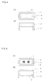
- Fig. 5a shows a top view showing an embodiment of the connector in accordance with the present invention.
- Fig. 5b shows a side view showing an embodiment of the connector in accordance with the present invention.
- Fig. 6 shows a longitudinal sectional view showing an example of the connector in accordance with the present invention attached to the substrate.
- Fig. 7a shows a view showing a claw shaped engaging part.
- Fig. 7b shows a view showing a spherical shaped engaging part.
- Fig. 7c shows a view showing a curved shaped engaging part.
- Fig. 7d shows a view showing an L shaped engaging part.
- An attaching part having engaging parts is formed by injection molding using nylon resin.
- a previously molded attaching part made of nylon resin is inserted in a metal mold, liquid silicone rubber mixed with nickel powder as a conductive medium is poured into the metal mold, and then a magnetic force is applied to a desired position in the metal mold so as to orient the nickel powder to define a conductive part. After that, the liquid silicone rubber is cross-linked, and an anisotropic connector part and the attaching part are integrated into one piece, thereby obtaining the connector of Embodiment 1.
- Fig. 3 is an assembly view of a simple attachment type connector in Example 1 of the present invention.
- a connector wherein the attaching part 4 made of nylon resin having the engaging parts 3 and the elastic anisotropic connector part 2 made of silicone rubber having the conductive part 1 formed by orienting nickel powder by means of magnetic force are integrated into one piece is attached to a substrate 7 with the conductive part 1 being contacted with electrodes 8 of the substrate 7.
- the anisotropic connector part 2 of the connector of Embodiment 1 is fitted into the attaching part 4 which is hollow.
- the anisotropic connector part 2 is compressed by an electronic part (not-shown) and the substrate and thereby shows a stable resistance value. Since the whole side surface of the anisotropic connector part 2 is not covered by the attaching part 4, the anisotropic connector part 2 is bent when being compressed, and therefore load in compression can be suppressed low.
- the engaging parts 3 are of outward claw shapes but may be of inward claw shapes. Moreover, by providing engaging parts on the top surface of the attaching part 4, it is also possible to facilitate attachment to the electronic parts.
- the attaching part 4 having engaging parts, as shown in Fig. 4 is formed by injection molding.
- Convex ribs 9 are provided on the inner peripheral side surface of a hollow portion of the attaching part.
- a previously molded attaching part 4 made of polyacetal resin is inserted in a metal mold, liquid silicone rubber mixed with gold-coated nickel powder as conductive medium is poured into the metal mold, and a magnetic force is applied to a desired position in the metal mold so as to orient the gold-coated nickel powder to specify a part of the conductive part 1 so as to form an anisotropic connector part 2. After that, the liquid silicone rubber is cross-linked to integrate the anisotropic connector part with the attaching part 4, thereby obtaining the connector of Embodiment 2.
- the method of manufacturing the connector in accordance with the present invention includes no soldering process for connecting lead wires, etc. and comprises only an assembly process of parts, and so the assembling can be simplified.
- the connector wherein the attaching part 4 made of polyacetal resin having the engaging part 3 and an elastic anisotropic connector part 2 made of silicone rubber having the conductive part 1 formed by orienting a desire position of gold-coated nickel powder by means of magnetic force are integrated into one piece is attached to the substrate 7 with the conductive part 1 being contacted with the electrode 8 of the substrate 7.
- the connector is used to connect electrodes of the electronic parts and electrodes of the substrate, the soldering process for connecting lead wires, etc. can be eliminated. Moreover, simplification of the assembly process allows reduction of the manufacturing cost. Further, since the connector has a conductive part formed by orienting a conductive medium by means of magnetic force, a stable electrical connection can be obtained even if load in compression is low, and pressure being applied to the inside of the case can be reduced.
- the manufacturing method of the present invention it is possible to easily manufacture the connector wherein the attaching part having engaging parts of complex shape as used for being fitted in substrate or electronic parts and the anisotropic connector part are integrated into one piece.
Landscapes
- Engineering & Computer Science (AREA)
- Manufacturing & Machinery (AREA)
- Manufacturing Of Electrical Connectors (AREA)
- Coupling Device And Connection With Printed Circuit (AREA)
- Connecting Device With Holders (AREA)
Applications Claiming Priority (2)
| Application Number | Priority Date | Filing Date | Title |
|---|---|---|---|
| JP2001241739 | 2001-08-09 | ||
| JP2001241739A JP4767450B2 (ja) | 2001-08-09 | 2001-08-09 | コネクタおよびその製造方法 |
Publications (3)
| Publication Number | Publication Date |
|---|---|
| EP1283563A2 true EP1283563A2 (fr) | 2003-02-12 |
| EP1283563A3 EP1283563A3 (fr) | 2004-02-04 |
| EP1283563B1 EP1283563B1 (fr) | 2005-07-20 |
Family
ID=19072130
Family Applications (1)
| Application Number | Title | Priority Date | Filing Date |
|---|---|---|---|
| EP02255557A Expired - Lifetime EP1283563B1 (fr) | 2001-08-09 | 2002-08-08 | Connecteur et méthode de fabrication |
Country Status (4)
| Country | Link |
|---|---|
| US (1) | US7097471B2 (fr) |
| EP (1) | EP1283563B1 (fr) |
| JP (1) | JP4767450B2 (fr) |
| DE (1) | DE60205070T2 (fr) |
Cited By (2)
| Publication number | Priority date | Publication date | Assignee | Title |
|---|---|---|---|---|
| WO2005005046A3 (fr) * | 2003-06-24 | 2005-08-11 | Hewlett Packard Development Co | Dispositif a systeme mecanique microelectrique fluidique |
| EP2040338A3 (fr) * | 2007-09-21 | 2010-01-13 | Mea Technologies Pte. Ltd. | Connecteur électrique |
Families Citing this family (8)
| Publication number | Priority date | Publication date | Assignee | Title |
|---|---|---|---|---|
| US8518304B1 (en) | 2003-03-31 | 2013-08-27 | The Research Foundation Of State University Of New York | Nano-structure enhancements for anisotropic conductive material and thermal interposers |
| JP2010528647A (ja) * | 2007-06-06 | 2010-08-26 | ドマンティス リミテッド | ポリペプチド、抗体可変ドメインおよびアンタゴニスト |
| CN201238089Y (zh) * | 2008-04-28 | 2009-05-13 | 番禺得意精密电子工业有限公司 | 具有识别功能的传导装置 |
| EP2679515B1 (fr) * | 2008-12-31 | 2014-07-02 | W.L. Gore & Associates GmbH | Dispositif d'aération |
| DE202012007354U1 (de) * | 2012-07-30 | 2013-08-01 | Jvk Filtration Systems Gmbh | Membran für eine Membranfilterplatte und Anordnung von zwei Filterplatten |
| EP2890226B1 (fr) * | 2012-08-24 | 2017-08-09 | Yazaki Corporation | Structure de raccordement destinée à un connecteur de substrat et procédé de raccordement |
| US9853383B2 (en) * | 2015-09-11 | 2017-12-26 | General Electric Company | Conductive polymer contacts for surface mount technology connectors |
| US20250201683A1 (en) * | 2023-12-19 | 2025-06-19 | Analog Devices, Inc. | Molded vertical interconnect array |
Family Cites Families (11)
| Publication number | Priority date | Publication date | Assignee | Title |
|---|---|---|---|---|
| US4664458A (en) * | 1985-09-19 | 1987-05-12 | C W Industries | Printed circuit board connector |
| US5045249A (en) * | 1986-12-04 | 1991-09-03 | At&T Bell Laboratories | Electrical interconnection by a composite medium |
| JP3038859B2 (ja) * | 1989-09-29 | 2000-05-08 | ジェイエスアール株式会社 | 異方導電性シート |
| US5163837A (en) * | 1991-06-26 | 1992-11-17 | Amp Incorporated | Ordered area array connector |
| US5232372A (en) * | 1992-05-11 | 1993-08-03 | Amp Incorporated | Land grid array connector and method of manufacture |
| JP2899543B2 (ja) * | 1995-06-08 | 1999-06-02 | 信越ポリマー株式会社 | 半導体パッケージ接続用ソケット |
| JPH0982431A (ja) * | 1995-09-19 | 1997-03-28 | Whitaker Corp:The | 電気コネクタ及びその製造方法 |
| JPH1140224A (ja) * | 1997-07-11 | 1999-02-12 | Jsr Corp | 異方導電性シート |
| JP3356971B2 (ja) * | 1997-09-03 | 2002-12-16 | 信越ポリマー株式会社 | マイクロフォンホルダ一体型コネクタ、その製造方法及びコネクタ付きコンデンサ型マイクロフォン |
| JP3283226B2 (ja) * | 1997-12-26 | 2002-05-20 | ポリマテック株式会社 | ホルダーの製造法 |
| JP4312890B2 (ja) * | 1999-08-02 | 2009-08-12 | ポリマテック株式会社 | ホルダ |
-
2001
- 2001-08-09 JP JP2001241739A patent/JP4767450B2/ja not_active Expired - Lifetime
-
2002
- 2002-08-01 US US10/210,502 patent/US7097471B2/en not_active Expired - Fee Related
- 2002-08-08 EP EP02255557A patent/EP1283563B1/fr not_active Expired - Lifetime
- 2002-08-08 DE DE60205070T patent/DE60205070T2/de not_active Expired - Lifetime
Cited By (4)
| Publication number | Priority date | Publication date | Assignee | Title |
|---|---|---|---|---|
| WO2005005046A3 (fr) * | 2003-06-24 | 2005-08-11 | Hewlett Packard Development Co | Dispositif a systeme mecanique microelectrique fluidique |
| US7309467B2 (en) | 2003-06-24 | 2007-12-18 | Hewlett-Packard Development Company, L.P. | Fluidic MEMS device |
| US8039205B2 (en) | 2003-06-24 | 2011-10-18 | Hewlett-Packard Development Company, L.P. | Fluidic MEMS device |
| EP2040338A3 (fr) * | 2007-09-21 | 2010-01-13 | Mea Technologies Pte. Ltd. | Connecteur électrique |
Also Published As
| Publication number | Publication date |
|---|---|
| EP1283563B1 (fr) | 2005-07-20 |
| DE60205070T2 (de) | 2006-05-24 |
| US7097471B2 (en) | 2006-08-29 |
| US20030032315A1 (en) | 2003-02-13 |
| DE60205070D1 (de) | 2005-08-25 |
| JP2003059601A (ja) | 2003-02-28 |
| EP1283563A3 (fr) | 2004-02-04 |
| JP4767450B2 (ja) | 2011-09-07 |
Similar Documents
| Publication | Publication Date | Title |
|---|---|---|
| US6613267B1 (en) | Method for manufacturing a holder | |
| US6630911B2 (en) | Compact antenna and producing method thereof | |
| EP1283563B1 (fr) | Connecteur et méthode de fabrication | |
| JP2004534436A (ja) | アンテナ構造体 | |
| JPH10262294A (ja) | 導電性ゴム接点を使用した小型マイク組立品 | |
| JP3658553B2 (ja) | ホルダー及び電子部品の導電接続構造 | |
| CN110957603A (zh) | 压接电连接器 | |
| CN112106258B (zh) | 压接电连接器 | |
| JP2024524705A (ja) | ガラス面上に形成された導体のための電気接続構造 | |
| JP4382255B2 (ja) | 小型音響素子のホルダ及び小型音響電子部品 | |
| JP4443751B2 (ja) | ホルダーおよびその製造方法 | |
| CN111180909B (zh) | 压接电连接器 | |
| CN111193115B (zh) | 压接电连接器 | |
| US20030074780A1 (en) | Three-dimensional elastomeric connector | |
| JP2002111368A (ja) | 携帯電話用内蔵アンテナ | |
| JP2001045583A (ja) | ホルダ | |
| JP2002057772A (ja) | ホルダー | |
| JP2002324599A (ja) | ホルダー及びその製造方法 | |
| JP4560195B2 (ja) | ホルダー | |
| KR100891792B1 (ko) | 이동통신 단말기용 내장형 안테나 장치 | |
| JP2005057422A (ja) | 導電性接続体およびそれを用いた電気音響変換器 | |
| JPH1188991A (ja) | コンデンサマイクロフォンの接続方法、接続構造 | |
| JP2004022510A (ja) | 電子部品用コネクタ | |
| JP2003272730A (ja) | フィルム状回路基板一体型弾性コネクタ | |
| JP2002222684A (ja) | 電気音響部品用コネクタ |
Legal Events
| Date | Code | Title | Description |
|---|---|---|---|
| PUAI | Public reference made under article 153(3) epc to a published international application that has entered the european phase |
Free format text: ORIGINAL CODE: 0009012 |
|
| AK | Designated contracting states |
Designated state(s): AT BE BG CH CY CZ DE DK EE ES FI FR GB GR IE IT LI LU MC NL PT SE SK TR |
|
| AX | Request for extension of the european patent |
Extension state: AL LT LV MK RO SI |
|
| 17P | Request for examination filed |
Effective date: 20030603 |
|
| PUAL | Search report despatched |
Free format text: ORIGINAL CODE: 0009013 |
|
| AK | Designated contracting states |
Kind code of ref document: A3 Designated state(s): AT BE BG CH CY CZ DE DK EE ES FI FR GB GR IE IT LI LU MC NL PT SE SK TR |
|
| AX | Request for extension of the european patent |
Extension state: AL LT LV MK RO SI |
|
| 17Q | First examination report despatched |
Effective date: 20040721 |
|
| AKX | Designation fees paid |
Designated state(s): DE FI GB NL SE |
|
| GRAP | Despatch of communication of intention to grant a patent |
Free format text: ORIGINAL CODE: EPIDOSNIGR1 |
|
| GRAS | Grant fee paid |
Free format text: ORIGINAL CODE: EPIDOSNIGR3 |
|
| GRAA | (expected) grant |
Free format text: ORIGINAL CODE: 0009210 |
|
| AK | Designated contracting states |
Kind code of ref document: B1 Designated state(s): DE FI GB NL SE |
|
| REG | Reference to a national code |
Ref country code: GB Ref legal event code: FG4D |
|
| REF | Corresponds to: |
Ref document number: 60205070 Country of ref document: DE Date of ref document: 20050825 Kind code of ref document: P |
|
| REG | Reference to a national code |
Ref country code: SE Ref legal event code: TRGR |
|
| PLBE | No opposition filed within time limit |
Free format text: ORIGINAL CODE: 0009261 |
|
| STAA | Information on the status of an ep patent application or granted ep patent |
Free format text: STATUS: NO OPPOSITION FILED WITHIN TIME LIMIT |
|
| 26N | No opposition filed |
Effective date: 20060421 |
|
| PGFP | Annual fee paid to national office [announced via postgrant information from national office to epo] |
Ref country code: FI Payment date: 20080901 Year of fee payment: 7 |
|
| PGFP | Annual fee paid to national office [announced via postgrant information from national office to epo] |
Ref country code: SE Payment date: 20080829 Year of fee payment: 7 |
|
| PG25 | Lapsed in a contracting state [announced via postgrant information from national office to epo] |
Ref country code: FI Free format text: LAPSE BECAUSE OF NON-PAYMENT OF DUE FEES Effective date: 20090808 |
|
| PGFP | Annual fee paid to national office [announced via postgrant information from national office to epo] |
Ref country code: NL Payment date: 20100810 Year of fee payment: 9 |
|
| PGFP | Annual fee paid to national office [announced via postgrant information from national office to epo] |
Ref country code: GB Payment date: 20100811 Year of fee payment: 9 |
|
| PG25 | Lapsed in a contracting state [announced via postgrant information from national office to epo] |
Ref country code: SE Free format text: LAPSE BECAUSE OF NON-PAYMENT OF DUE FEES Effective date: 20090809 |
|
| PGFP | Annual fee paid to national office [announced via postgrant information from national office to epo] |
Ref country code: DE Payment date: 20110803 Year of fee payment: 10 |
|
| REG | Reference to a national code |
Ref country code: NL Ref legal event code: V1 Effective date: 20120301 |
|
| GBPC | Gb: european patent ceased through non-payment of renewal fee |
Effective date: 20110808 |
|
| PG25 | Lapsed in a contracting state [announced via postgrant information from national office to epo] |
Ref country code: NL Free format text: LAPSE BECAUSE OF NON-PAYMENT OF DUE FEES Effective date: 20120301 |
|
| PG25 | Lapsed in a contracting state [announced via postgrant information from national office to epo] |
Ref country code: GB Free format text: LAPSE BECAUSE OF NON-PAYMENT OF DUE FEES Effective date: 20110808 |
|
| PG25 | Lapsed in a contracting state [announced via postgrant information from national office to epo] |
Ref country code: DE Free format text: LAPSE BECAUSE OF NON-PAYMENT OF DUE FEES Effective date: 20130301 |
|
| REG | Reference to a national code |
Ref country code: DE Ref legal event code: R119 Ref document number: 60205070 Country of ref document: DE Effective date: 20130301 |