EP1283743B1 - Ensemble doseur ameliore - Google Patents
Ensemble doseur ameliore Download PDFInfo
- Publication number
- EP1283743B1 EP1283743B1 EP01920905A EP01920905A EP1283743B1 EP 1283743 B1 EP1283743 B1 EP 1283743B1 EP 01920905 A EP01920905 A EP 01920905A EP 01920905 A EP01920905 A EP 01920905A EP 1283743 B1 EP1283743 B1 EP 1283743B1
- Authority
- EP
- European Patent Office
- Prior art keywords
- liquid
- feed line
- valve
- collecting vessel
- ball valve
- Prior art date
- Legal status (The legal status is an assumption and is not a legal conclusion. Google has not performed a legal analysis and makes no representation as to the accuracy of the status listed.)
- Expired - Lifetime
Links
- 239000007788 liquid Substances 0.000 claims abstract description 91
- 239000003086 colorant Substances 0.000 claims abstract description 64
- 239000006260 foam Substances 0.000 claims abstract description 41
- 229920002635 polyurethane Polymers 0.000 claims abstract description 12
- 239000004814 polyurethane Substances 0.000 claims abstract description 12
- 238000003860 storage Methods 0.000 claims description 19
- 229920005862 polyol Polymers 0.000 claims description 18
- 150000003077 polyols Chemical class 0.000 claims description 18
- 238000000034 method Methods 0.000 claims description 12
- 230000009471 action Effects 0.000 claims description 10
- 239000000203 mixture Substances 0.000 claims description 7
- 239000000654 additive Substances 0.000 claims description 6
- 239000000049 pigment Substances 0.000 claims description 5
- 239000003054 catalyst Substances 0.000 claims description 3
- 239000004094 surface-active agent Substances 0.000 claims description 3
- 239000003063 flame retardant Substances 0.000 claims description 2
- 230000000717 retained effect Effects 0.000 claims description 2
- XLYOFNOQVPJJNP-UHFFFAOYSA-N water Substances O XLYOFNOQVPJJNP-UHFFFAOYSA-N 0.000 claims description 2
- 230000000996 additive effect Effects 0.000 claims 2
- RNFJDJUURJAICM-UHFFFAOYSA-N 2,2,4,4,6,6-hexaphenoxy-1,3,5-triaza-2$l^{5},4$l^{5},6$l^{5}-triphosphacyclohexa-1,3,5-triene Chemical compound N=1P(OC=2C=CC=CC=2)(OC=2C=CC=CC=2)=NP(OC=2C=CC=CC=2)(OC=2C=CC=CC=2)=NP=1(OC=1C=CC=CC=1)OC1=CC=CC=C1 RNFJDJUURJAICM-UHFFFAOYSA-N 0.000 claims 1
- 239000011369 resultant mixture Substances 0.000 claims 1
- 238000004519 manufacturing process Methods 0.000 abstract description 12
- 239000002699 waste material Substances 0.000 abstract description 12
- 230000004044 response Effects 0.000 abstract description 11
- 238000005259 measurement Methods 0.000 abstract description 4
- 230000009467 reduction Effects 0.000 abstract description 3
- 239000000376 reactant Substances 0.000 abstract description 2
- 238000004040 coloring Methods 0.000 description 13
- 229920005830 Polyurethane Foam Polymers 0.000 description 8
- 239000011496 polyurethane foam Substances 0.000 description 8
- 239000006185 dispersion Substances 0.000 description 5
- 239000012948 isocyanate Substances 0.000 description 4
- 150000002513 isocyanates Chemical class 0.000 description 4
- 238000002156 mixing Methods 0.000 description 4
- 238000005086 pumping Methods 0.000 description 4
- 230000000712 assembly Effects 0.000 description 3
- 238000000429 assembly Methods 0.000 description 3
- 230000008901 benefit Effects 0.000 description 3
- 230000008859 change Effects 0.000 description 3
- 230000001747 exhibiting effect Effects 0.000 description 3
- 238000002347 injection Methods 0.000 description 3
- 239000007924 injection Substances 0.000 description 3
- 239000000463 material Substances 0.000 description 3
- 238000007789 sealing Methods 0.000 description 3
- 238000013019 agitation Methods 0.000 description 2
- 238000013459 approach Methods 0.000 description 2
- UHZZMRAGKVHANO-UHFFFAOYSA-M chlormequat chloride Chemical compound [Cl-].C[N+](C)(C)CCCl UHZZMRAGKVHANO-UHFFFAOYSA-M 0.000 description 2
- 238000006073 displacement reaction Methods 0.000 description 2
- 230000008030 elimination Effects 0.000 description 2
- 230000006870 function Effects 0.000 description 2
- 238000007373 indentation Methods 0.000 description 2
- 230000004048 modification Effects 0.000 description 2
- 238000012986 modification Methods 0.000 description 2
- 230000006641 stabilisation Effects 0.000 description 2
- 238000011105 stabilization Methods 0.000 description 2
- 239000010935 stainless steel Substances 0.000 description 2
- 229910001220 stainless steel Inorganic materials 0.000 description 2
- 239000004604 Blowing Agent Substances 0.000 description 1
- 229910000975 Carbon steel Inorganic materials 0.000 description 1
- RTAQQCXQSZGOHL-UHFFFAOYSA-N Titanium Chemical compound [Ti] RTAQQCXQSZGOHL-UHFFFAOYSA-N 0.000 description 1
- 150000001298 alcohols Chemical class 0.000 description 1
- 238000005452 bending Methods 0.000 description 1
- 230000000740 bleeding effect Effects 0.000 description 1
- 239000010962 carbon steel Substances 0.000 description 1
- 238000006243 chemical reaction Methods 0.000 description 1
- 238000004140 cleaning Methods 0.000 description 1
- 150000001875 compounds Chemical class 0.000 description 1
- 238000010924 continuous production Methods 0.000 description 1
- 230000003111 delayed effect Effects 0.000 description 1
- 230000001419 dependent effect Effects 0.000 description 1
- 238000013461 design Methods 0.000 description 1
- 230000001627 detrimental effect Effects 0.000 description 1
- 238000010586 diagram Methods 0.000 description 1
- 239000000975 dye Substances 0.000 description 1
- 230000000694 effects Effects 0.000 description 1
- 238000003379 elimination reaction Methods 0.000 description 1
- 239000012530 fluid Substances 0.000 description 1
- 230000004907 flux Effects 0.000 description 1
- 239000006261 foam material Substances 0.000 description 1
- 238000005187 foaming Methods 0.000 description 1
- 239000000446 fuel Substances 0.000 description 1
- 230000006872 improvement Effects 0.000 description 1
- 238000010348 incorporation Methods 0.000 description 1
- 230000000977 initiatory effect Effects 0.000 description 1
- 239000002075 main ingredient Substances 0.000 description 1
- 230000014759 maintenance of location Effects 0.000 description 1
- 230000007246 mechanism Effects 0.000 description 1
- 229910052751 metal Inorganic materials 0.000 description 1
- 239000002184 metal Substances 0.000 description 1
- 150000002978 peroxides Chemical class 0.000 description 1
- 230000002265 prevention Effects 0.000 description 1
- 239000007787 solid Substances 0.000 description 1
- 239000002904 solvent Substances 0.000 description 1
- 238000010186 staining Methods 0.000 description 1
- 239000000758 substrate Substances 0.000 description 1
- 239000010936 titanium Substances 0.000 description 1
- 229910052719 titanium Inorganic materials 0.000 description 1
- -1 without limitation Substances 0.000 description 1
Images

Classifications
-
- B—PERFORMING OPERATIONS; TRANSPORTING
- B01—PHYSICAL OR CHEMICAL PROCESSES OR APPARATUS IN GENERAL
- B01F—MIXING, e.g. DISSOLVING, EMULSIFYING OR DISPERSING
- B01F35/00—Accessories for mixers; Auxiliary operations or auxiliary devices; Parts or details of general application
- B01F35/80—Forming a predetermined ratio of the substances to be mixed
- B01F35/83—Forming a predetermined ratio of the substances to be mixed by controlling the ratio of two or more flows, e.g. using flow sensing or flow controlling devices
- B01F35/834—Forming a predetermined ratio of the substances to be mixed by controlling the ratio of two or more flows, e.g. using flow sensing or flow controlling devices the flow of substances to be mixed circulating in a closed circuit, e.g. from a container through valve, driving means, metering means or dispensing means, e.g. 3-way valve, and back to the container
-
- B—PERFORMING OPERATIONS; TRANSPORTING
- B01—PHYSICAL OR CHEMICAL PROCESSES OR APPARATUS IN GENERAL
- B01F—MIXING, e.g. DISSOLVING, EMULSIFYING OR DISPERSING
- B01F35/00—Accessories for mixers; Auxiliary operations or auxiliary devices; Parts or details of general application
- B01F35/71—Feed mechanisms
- B01F35/712—Feed mechanisms for feeding fluids
-
- B—PERFORMING OPERATIONS; TRANSPORTING
- B01—PHYSICAL OR CHEMICAL PROCESSES OR APPARATUS IN GENERAL
- B01F—MIXING, e.g. DISSOLVING, EMULSIFYING OR DISPERSING
- B01F35/00—Accessories for mixers; Auxiliary operations or auxiliary devices; Parts or details of general application
- B01F35/71—Feed mechanisms
- B01F35/717—Feed mechanisms characterised by the means for feeding the components to the mixer
- B01F35/71805—Feed mechanisms characterised by the means for feeding the components to the mixer using valves, gates, orifices or openings
-
- B—PERFORMING OPERATIONS; TRANSPORTING
- B29—WORKING OF PLASTICS; WORKING OF SUBSTANCES IN A PLASTIC STATE IN GENERAL
- B29B—PREPARATION OR PRETREATMENT OF THE MATERIAL TO BE SHAPED; MAKING GRANULES OR PREFORMS; RECOVERY OF PLASTICS OR OTHER CONSTITUENTS OF WASTE MATERIAL CONTAINING PLASTICS
- B29B7/00—Mixing; Kneading
- B29B7/30—Mixing; Kneading continuous, with mechanical mixing or kneading devices
- B29B7/58—Component parts, details or accessories; Auxiliary operations
- B29B7/60—Component parts, details or accessories; Auxiliary operations for feeding, e.g. end guides for the incoming material
-
- B—PERFORMING OPERATIONS; TRANSPORTING
- B29—WORKING OF PLASTICS; WORKING OF SUBSTANCES IN A PLASTIC STATE IN GENERAL
- B29K—INDEXING SCHEME ASSOCIATED WITH SUBCLASSES B29B, B29C OR B29D, RELATING TO MOULDING MATERIALS OR TO MATERIALS FOR MOULDS, REINFORCEMENTS, FILLERS OR PREFORMED PARTS, e.g. INSERTS
- B29K2075/00—Use of PU, i.e. polyureas or polyurethanes or derivatives thereof, as moulding material
-
- B—PERFORMING OPERATIONS; TRANSPORTING
- B29—WORKING OF PLASTICS; WORKING OF SUBSTANCES IN A PLASTIC STATE IN GENERAL
- B29K—INDEXING SCHEME ASSOCIATED WITH SUBCLASSES B29B, B29C OR B29D, RELATING TO MOULDING MATERIALS OR TO MATERIALS FOR MOULDS, REINFORCEMENTS, FILLERS OR PREFORMED PARTS, e.g. INSERTS
- B29K2105/00—Condition, form or state of moulded material or of the material to be shaped
- B29K2105/0005—Condition, form or state of moulded material or of the material to be shaped containing compounding ingredients
- B29K2105/0032—Pigments, colouring agents or opacifiyng agents
-
- B—PERFORMING OPERATIONS; TRANSPORTING
- B29—WORKING OF PLASTICS; WORKING OF SUBSTANCES IN A PLASTIC STATE IN GENERAL
- B29K—INDEXING SCHEME ASSOCIATED WITH SUBCLASSES B29B, B29C OR B29D, RELATING TO MOULDING MATERIALS OR TO MATERIALS FOR MOULDS, REINFORCEMENTS, FILLERS OR PREFORMED PARTS, e.g. INSERTS
- B29K2105/00—Condition, form or state of moulded material or of the material to be shaped
- B29K2105/04—Condition, form or state of moulded material or of the material to be shaped cellular or porous
Definitions
- This invention relates to an improved dosing assembly (valve/feed line/liquid collecting vessel) which permits nearly immediate response time to an actuator signal.
- an assembly is used for the controlled introduction of any liquid through a valve into a collecting vessel.
- the inventive assembly exhibits substantially no leakage from the feed line into the liquid collecting vessel when the valve is closed and an instantaneous introduction of the feed line liquid into the liquid collecting vessel upon opening of the valve, when a liquid possessing a surface tension of about 5 Pa (50 dynes/cm 2) is used as the measurement standard.
- This assembly is particularly and preferably suited for injecting colorants into reactants for the production of polyurethane slabstock foam and permits a substantial reduction in foam waste due to low colorations during an on/off cycle.
- this inventive assembly comprises a ball valve, a manifold, and a connector pipe which may contain at most 30 mL of liquid at any single moment and which is measured in diameter of at most 1.07 cm (0.42 inches).
- a connecting pipe permits substantially instantaneous shut-off and -on without appreciable leakage or pressure drop and without the need to utilize a high throughput flow rate. Also, such a specific connecting pipe is wide enough to permit high through-put rates should the need arise.
- the valve/pipe/manifold configuration is contemplated within this invention.
- Polymeric colorants such as those cited above in Cross et al. were designed to be totally miscible with one another as well as with most polyols, one of the two main ingredients used to produce polyurethane materials (isocyanates being the other).
- Pigment dispersions are particulates dispersed in some type of liquid carrier. They require a high degree of agitation before they satisfactorily blend together to provide a uniform color. As a result the short amount of time that the polyol and colorant are mixed in the typical slabstock foam machine's mixhead may not be sufficient to produce an adequate mixture of components to insure a single, homogeneous coloration throughout the target foam.
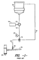
- FIG.1 A configuration of this "new" (now typical) on-the-fly colorant production line for slabstock foam is depicted in FIG.1.
- This new coloring system itself generally consisted of 4 to 6 "primary" color storage tanks (one of which is depicted as 10 in FIG. 1) each feeding color to at least one positive displacement spur gear pump 12 coupled to a variable speed motor/drive 14 (such as available from Viking).
- the motor/pump combination 12,14 was typically run continuously in either recirculation or dispense mode (depending on the position of a 3-way valve 16) to minimize the time required to spool up the motor 14 to the proper rpm and to ultimately achieve the pressure required to initiate color flow into a pre-mix manifold 18 through an injector 20.
- the throughput pressure was typically measured through the utilization of a pressure gauge 25 attached to the feed line 13 from the pump 12 to the 3-way valve 16.
- the typical 3-way valve 16 was air actuated and used to direct the flow of colorant from the recirculation feed line 22 to the dispense feed line 24 (to the injector 20) when color flow to the manifold 18 was required. From the manifold 18, the colorant(s) was moved to the mixing head 26 and then further on to color the target slabstock foam (not illustrated).
- the market place demands that a foam producer be able to provide dark shades as well as light shades with a variety of hues and polyol flow rates. Since color is metered volumetrically a wide range of color flow rates are required to insure low enough flow for a minor component in a light shade.
- the polyol flow rates can be as low as 10 kg/min and as high as 300 kg/min [color loading is generally stated in parts per hundred polyol (php)]. As the rate at which the polyol flows is reduced so must the color rate be reduced to maintain the same php. For most foam manufacturing plants in the United States and elsewhere the color delivery systems must be able to provide color flow as low as 2 grams/min and as high as 7000 grams/min or more.
- the colorant continues to move through the feed line until it reaches the manifold and then, hopefully, mixes evenly and thoroughly within the polyol component.
- the colorant stops moving into the feed line; however, there is a certain amount remaining within the feed line which continues to move through unevenly.
- the polyol would thus be discolored or colored unevenly (which thus produces waste foam) itself upon introduction of the residual feed line colorant.
- a further object of the invention is to provide a low throughput flow rate method of coloring polyurethane slabstock foam with a colorant injection which substantially reduces and possibly eliminates the production of off-quality, improperly colored waste foam materials.
- this invention encompasses a liquid dosing assembly as claimed in claim 1 and a method as claimed in claim 7 below.
- EP 1,031,776 A (comprised in the state of the art pursuant to Art. 54 (3), (4) EPC). This document does not, however, disclose a defined storage capacity and a defined diameter such that a liquid in the feed line is subjected to capillary action.
- the "liquid" utilized within the inventive assembly may be a pigment dispersion, or the like, which comprises an appreciable solids content. Such dispersions, etc., may be utilized within the inventive assembly.
- liquid collecting vessel is intended to encompass any possible vessel into which the liquid transported through the valve and feed line may be stored, either temporarily or permanently.
- this term may, as merely a few examples, encompass, a manifold pipe, a storage container, including, again, as merely examples, a storage tank (either immobile or mobile; i.e., a ground tank or vehicle tank), and the like. Therefore, any liquid may be transported through utilization of the inventive dosing assembly, including, organic liquids, such as, without limitation, colorants, dyes, alcohols, fuels, and the like; inorganic liquids, such as, peroxides, water, and the like.
- sample polyurethane foam is a well known description of cured polyurethane foam, made from the reaction of polyols and isocyanates.
- other components are added to such foam products in relatively low proportions, such as, without limitations, surfactants, catalysts, flame retardants, blowing agents, and the like.
- these other additives may also be introduced within polyurethane slabstock foam (as well as many other end-use products) with this particular device.
- the inventive assembly beneficially and surprisingly permits controlled dosage of any liquid (or dispersed) additives at a selected rate and in a selected amount.
- the inventive dosing assembly provides the ability to control dosage at any preselected time or level or proportions within a target composition within the liquid collecting vessel portion of the inventive assembly.
- valve is intended to encompass an individual assembly comprising a specific valve but which may include a pipe or channel of some type leading into the feed line component of the inventive dosing assembly.
- feed line is intended to mean a connecting pipe (preferably cylindrical, or at least, substantially cylindrical, in shape) between the valve and liquid collecting vessel. The feed line must connect simultaneously to both the valve and the liquid collecting assembly in such a fashion as to permit one-way movement of any liquid introduced within the dosing assembly from the valve component to the collecting vessel (or vice-versa, possibly).
- substantially no leakage as it pertains to the functional characteristics of the inventive dosing assembly simply describes the extremely low amount of liquid which may move out of the feed line into the collecting vessel once the valve is closed. This leakage of only low amount of moved liquids is accomplished through the vacuum seal provided by the closed valve supplemented with the cohesion of the liquid and adhesion of the liquid to the feed line walls (both through capillary action).
- injectors such as spring-loaded or plunger types
- check valves such as spring-loaded and/or plunger types
- Such injectors and/or check valves have proven to be very troublesome to use, particularly in low throughput pressure applications, due to the leakability of liquids accumulating at metal-metal separatable interfaces.
- no spring-loaded injectors or check valves are utilized; only vacuum sealing and capillary action provide the necessary suction to retain substantially all of the introduced liquid within the feed line.
- the term "substantially” in this instance requires that all but a few drops of liquid must be retained; this amount should aggregately add up to no more than about 5% of the total storage capacity of the feed line after about 1 hour of valve closure; preferably, this amount is no more than about 1%, more preferably no more than about 0.1%, and, of course, most preferably no liquid leakage occurs after such a period of time.
- the feed line must retain all but the same amount of liquid permitted to leak from the feed line into the liquid collecting vessel after valve closure.
- the liquid present within the feed line must remain there through vacuum sealing provided by the closed valve and the capillary action (adhesion and cohesion) provided by the liquid in contact with the feed line inner surface.
- the inventive dosing assembly may be defined in terms of the storage capacity volume and orifice size of the feed line alone. Such characteristics contribute to the desired capillary action necessary to effectuate the non-leakage benefits in tandem with the vacuum seal of the closed valve.
- a 30 mL storage capacity coupled with an orifice size (feed line diameter) of at most 1.07 cm (0.42 inches) should provide the desired functions (i.e., non-leakage and instantaneous response time).
- the storage capacity is about 10 mL and the diameter is at most 0.84 cm (0.33 inches); more preferably, these are about 5 mL and 0.635 cm (0.25 inches), respectively; most preferably, about 4 mL and 0.475 cm (0.187 inches), respectively; also preferable is a low throughput pressure system comprising the inventive assembly exhibiting a feed line storage capacity of as low as about 1 mL and an orifice size (diameter) of about 0.198 cm (0.078 inches).
- the instant invention solves the problems associated with prior dosing assemblies, particularly for, but not limited to, slabstock polyurethane foam production lines.
- the special low-volume feed line was developed to best ensure prevention of leakage from the feed line to the liquid collecting vessel upon shut-off of the valve.
- the seal pressure of the valve coupled with the capillary action, adhesion, and/or cohesion of the liquid to the feed line walls or to itself, provides an extremely reliable dosing assembly from a leakage standpoint. This is highly desirable, particularly where the liquid collecting vessel is intended to be kept clear of dosed liquid at selected times.
- the feed line itself is preferably connected simultaneously to both the valve and the liquid collecting vessel (in order to transport a liquid through the valve and feed line into the vessel itself); however, if desired or necessary, the feed line may only lead into the liquid collecting vessel; a connection with such a component is not required.
- the only limitations concerning the feed line pertain to the available volume and the maximum diameter; generally, any length of feed line may be utilized as long as the volume and diameter requirements are not exceeded.
- the ball valve are 3-way ball valve configurations which permit more reliable shut-off and -on. Any 3-way ball valve may thus be utilized in this invention.
- One preferred ball valve is taught within U.S. Patent Application No. 09/259,114 to Ragsdale et al. Such a specific ball valve (which is a spherical ball valve) configuration facilitates an instantaneous on/off switching between a dispensing feed line to an injector unit and a feed line to a recirculation assembly (to reduce the amount of colorant potentially wasted and to best insure the throughput pressure of the entire apparatus remains uniform at all times).
- this preferred ball valve comprises two exclusive channels, one of which is positioned to direct the flow of colorant to the recirculation assembly and the other to direct such a flow to the injector.
- the configuration of the non-x-axis channel reduces the change of pressure on the liquid colorant through the valve than with a standard right angle bending channel (it provides a sort of shunt).
- a ball valve has proven to be invaluable in providing the necessary instantaneous on/off (color response) times as well as maintaining the proper flow rate (at an extremely wide range from about 0.3 g/min to about 14,000 g/min).
- An actuator is utilized, generally, to rotate this ball valve into these specific positions.
- Such an actuator includes a pin extending into the valve assembly, the end of which pin is shaped to fit an indentation in the ball valve. The actuator then turns the ball valve the requisite number of degrees to align the respective channel to the desired feed line (90° is preferred, although, in some instances, 180° may be possible).
- the overall colorant flow rate may oscillate to an abnormally low rate (to compensate for the pressure existing between the valve and the manifold) prior to its ultimate stabilization. This may require several seconds (i.e., less than 1 minute, more likely about 30 seconds) of stabilization time which, again, may result in waste off-quality foam product.
- waste (off-quality) foam production has been attributed to delayed colorant flow (throughput flow rate), pressure drop, and turbulence problems, which themselves are caused by varying bore sizes between the three-way valve, the colorant dispensing feed line (to the injector), and the injector within standard polyurethane slabstock foam coloring apparatus.
- the inventive dosing assembly exhibits substantially the same bore size through the valve and the feed line to compensate for any such problems.
- Such similar bore sizes are preferred within the inventive assembly; however, such similarities are not totally required because the feed line limitations also compensate for such problems and have proven effective without the necessity of restricting bore size variations.
- the feed line may be tapered at the end leading to the collecting vessel in order to aid in the restriction of leaking liquid.
- the invention permits a substantial reduction (almost total elimination) of waste foam upon the utilization of very low, but highly desirable, flow rates and also allows for the utilization of an extremely wide range of flow rates without an appreciable pressure drop through the entire apparatus.
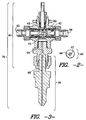
- the spherical ball valve 40 of FIG. 2 which may be made from stainless steel (preferably), titanium, carbon steel, and the like, comprises a first channel 42 which runs through the entire sphere on one single axis (the x-axis, for instance) and at a specific angle (such that the entire channel 42 is located at 0° on the x-axis).
- the ball valve 40 also comprises a second channel 44 which runs through the entire sphere on one single axis exclusive of the first channel 42 (here the y-axis although the z-axis is also possible) and at a specific angle (such that the channel 44 enters the ball valve 40 at a point at approximately 0° on the sphere in the y-axis and exits the ball valve 40 at a point 90° from the other entry but still in the same axis.
- the first channel 42 permits flow of the liquid colorant (not illustrated) through the valve 40 to a recirculation feed line (58 of FIG. 3) when aligned with the inlet feed line (52 of FIG. 3) from a storage tank (72 of FIG. 4).
- the first channel 42 Upon rotation of 90° by the utilization of an actuator pin (60 of FIG. 3) attached to an actuator (62 of FIG. 3) engaged with a properly shaped indentation (not illustrated) located at the point 270° on the y-axis in and of the ball valve 40, the first channel 42 is disengaged from all of its corresponding feed lines (52, 58 of FIG. 3) and permits the flow of liquid colorant (such as polymeric colorants, not illustrated) through the ball valve 40 (43 of FIG. 3), through an attached pipe (64 of FIG. 3) and into the collecting vessel (dispensing) feed line (68 of FIG. 3).
- liquid colorant such as polymeric colorants, not illustrated
- each channel 42, 44 is the same for each; however, the actual size of both bores in said channels 42, 44 may be of any size as long as they are preferably the same size as the bore of the inlet feed line (52 of FIG. 3), the recirculation feed line (58 of FIG. 3), the attached pipe (64 of FIG. 3), and the dispensing feed line (64 of FIG. 4).
- the ball valve 40 (43 of FIG. 3) size is merely dependent upon the amount of space between all of the feed lines (52, 58, 64 of FIG. 3) within the entire valve assembly (41 of FIG. 4).
- the dispensing feed line (68 of FIG. 3) permits the flow of the liquid colorant (not illustrated) into the manifold (82 of FIG. 4).
- the dispensing feed line (68 of FIG. 3) may be preferably attached to the valve assembly 41 by way of a screw mechanism (not illustrated), although any other means, such as welds, snaps, pins, and the like, may also be utilized for such a purpose.
- the dispensing feed line (66 of FIG. 3) in this instance exhibits a storage capacity volume of about 4 mL and an orifice size (diameter) of about 0.475 cm (0.187 inches).
- FIG. 4 thus incorporates the preferred dosing assembly (70 of FIG. 3) into the entire slabstock foam coloring apparatus and procedure.
- the colorant is transported from a storage tank 72 to at least one positive displacement spur gear pump 74 coupled to a variable speed motor/drive 76 (such as available from Viking).
- the motor/pump combination 74, 76 is run continuously in either recirculation or dispense mode (depending on the position of the 3-way valve 78).
- dispense mode the colorant flows through the injector 80 into a pre-mix manifold 82.
- the throughput pressure is measured through the utilization of a pressure gauge 84 attached to the feed line 85 from the pump 74 to the 3-way valve 78.
- the 3-way valve 78 is air actuated (although any other type of actuator may be used) and directs the flow of colorant from the recirculation feed line 86 to the dispense feed line 80) when color flow to the manifold 82 is desired. From the manifold 82, the colorant is moved to a mixing head 88 and then further on to color the target slabstock foam (not illustrated).
- valve 78 Upon orientation of the valve 78 into its closed position, and with a dispense feed line 80, exhibiting a volume of about 27.2 mL and a pipe diameter of about 1.07 cm (0.42 inches) (with a length of about 30 cm (1 foot)), dispensing of a 5 Pa (50 dynes/cm 2 ) colorant (in this instance REACTINT® Blue X17, available from Milliken & Company) stops immediately from the dispensing feed line to the manifold 82; even after 1 hour of closure of the valve 78, there is no noticeable leakage of the colorant from the feed line to the manifold 82.
- a 5 Pa (50 dynes/cm 2 ) colorant in this instance REACTINT® Blue X17, available from Milliken & Company
- the colorant Upon rotation of the ball valve 78 to its open position, the colorant instantaneously (i.e., within 1 second, preferably within 0.5 second, and most preferably within 0.1 second) enters the manifold 82 and begins to mix with the polyol.
- Altering the size of the feed line in both volume and diameter resulted in the following measurements, presented in tabular form with a pass rating symbolizing substantially no leakage after 1 hour of valve closure and instantaneous movement of the liquid into the manifold through the feed line after opening of the valve.
- a fail rating symbolizes leakage, too long response time, or both.
- the assembly may be oriented on its horizontally, vertically (either upside down or, preferably right side up), and at any angle in relation to the system in which it is integrated.
Landscapes
- Chemical & Material Sciences (AREA)
- Chemical Kinetics & Catalysis (AREA)
- Engineering & Computer Science (AREA)
- Mechanical Engineering (AREA)
- Casting Or Compression Moulding Of Plastics Or The Like (AREA)
- Polyurethanes Or Polyureas (AREA)
- Seal Device For Vehicle (AREA)
- Pharmaceuticals Containing Other Organic And Inorganic Compounds (AREA)
- Infusion, Injection, And Reservoir Apparatuses (AREA)
- Processing And Handling Of Plastics And Other Materials For Molding In General (AREA)
- Accessories For Mixers (AREA)
- Materials For Medical Uses (AREA)
- Feeding, Discharge, Calcimining, Fusing, And Gas-Generation Devices (AREA)
- Closures For Containers (AREA)
Claims (7)
- Ensemble de dosage de liquide comprenant un robinet à boisseau sphérique (40, 78), une conduite d'alimentation (68, 80), et un récipient de recueil de liquide (82), dans lequel
ladite conduite d'alimentation (68, 80) agit comme un conduit de transport entre ledit robinet à boisseau sphérique (40, 78) et ledit récipient de recueil de liquide (28),
la conduite d'alimentation a un volume de capacité de stockage défini et un diamètre défini de sorte qu'un liquide dans la conduite d'alimentation est soumis à une action capillaire et ledit ensemble de dosage de liquide ne présente pratiquement aucune fuite dudit liquide depuis ladite conduite d'alimentation (68, 80) dans le récipient de recueil de liquide (82) lorsque ledit robinet à boisseau sphérique (40, 78) est orienté dans la position fermée, grâce à ladite action capillaire à l'intérieur de la conduite d'alimentation (68, 80), de sorte que pratiquement tout ledit liquide est retenu à l'intérieur de ladite conduite d'alimentation (68, 80) par ladite action capillaire au moment où ledit robinet à boisseau sphérique (40, 78) est orienté dans la position fermée et, lors de la réorientation dudit robinet à boisseau sphérique (68, 80) de la position fermée à la position ouverte, ledit liquide se déplace instantanément dans le récipient de recueil de liquide (82). - Ensemble de dosage de liquide selon la revendication 1, en combinaison avec le liquide, le liquide possédant une tension superficielle d'environ 5 Pa (50 dynes/cm2).
- Ensemble de dosage de liquide selon la revendication 1 ou 2, dans lequel ladite conduite d'alimentation (68, 80) se relie simultanément audit robinet à boisseau sphérique (40, 78) et alimente ledit récipient de recueil de liquide (82), et où ladite conduite d'alimentation (68, 80) présente une capacité de stockage de liquide d'au plus 30 ml, et présente un diamètre d'au plus 1,07 cm.
- Ensemble de dosage de liquide selon l'une quelconque des revendications 1 à 3, dans lequel ledit récipient de recueil de liquide (82) est un tuyau distributeur.
- Ensemble de dosage de liquide selon l'une quelconque des revendications 1 à 4, dans lequel ledit robinet à boisseau sphérique est un robinet à boisseau sphérique à trois voies comprenant au moins un canal.
- Ensemble de dosage de liquide selon la revendication 3, dans lequel ladite conduite d'alimentation (68, 80) présente une capacité de stockage de liquide d'au plus 10 ml et un diamètre d'au plus 8,38 mm (0,33 pouces), de préférence une capacité de stockage de liquide d'au plus 4 ml et un diamètre d'au plus 4,75 mm (0,187 pouce), et de façon plus préférée une capacité de stockage de liquide d'au plus 1 ml et un diamètre d'au plus 1,98 mm (0,078 pouce).
- Procédé d'introduction commandée d'additifs à l'intérieur d'un système de production de pain de mousse de polyuréthane utilisant l'ensemble de dosage selon l'une quelconque des revendications précédentes, ledit procédé comprenant les étapes consistant à(a) fournir un polyalcool liquide à l'intérieur dudit tuyau distributeur,(b) introduire au moins un additif liquide parmi le groupe constitué d'au moins un colorant, d'au moins un pigment, d'au moins un colorant polymère, d'au moins un catalyseur, d'au moins un agent tensioactif, d'au moins un retardateur de combustion, d'eau et de tout mélange de ceux-ci, dans ledit tuyau distributeur par l'intermédiaire de ladite conduite d'alimentation pour former un mélange résultant dudit polyalcool liquide et dudit au moins un additif liquide.
Applications Claiming Priority (3)
| Application Number | Priority Date | Filing Date | Title |
|---|---|---|---|
| US578535 | 1984-02-09 | ||
| US09/578,535 US6378734B1 (en) | 2000-05-24 | 2000-05-24 | Dosing assembly |
| PCT/US2001/010415 WO2001089677A1 (fr) | 2000-05-24 | 2001-04-02 | Ensemble doseur ameliore |
Publications (2)
| Publication Number | Publication Date |
|---|---|
| EP1283743A1 EP1283743A1 (fr) | 2003-02-19 |
| EP1283743B1 true EP1283743B1 (fr) | 2005-08-31 |
Family
ID=24313282
Family Applications (1)
| Application Number | Title | Priority Date | Filing Date |
|---|---|---|---|
| EP01920905A Expired - Lifetime EP1283743B1 (fr) | 2000-05-24 | 2001-04-02 | Ensemble doseur ameliore |
Country Status (11)
| Country | Link |
|---|---|
| US (2) | US6378734B1 (fr) |
| EP (1) | EP1283743B1 (fr) |
| JP (1) | JP3768884B2 (fr) |
| CN (1) | CN1195579C (fr) |
| AT (1) | ATE303201T1 (fr) |
| AU (2) | AU4791301A (fr) |
| BR (1) | BR0111005A (fr) |
| DE (1) | DE60113097T2 (fr) |
| MX (1) | MXPA02010700A (fr) |
| NO (1) | NO20025599L (fr) |
| WO (1) | WO2001089677A1 (fr) |
Families Citing this family (17)
| Publication number | Priority date | Publication date | Assignee | Title |
|---|---|---|---|---|
| US7306338B2 (en) | 1999-07-28 | 2007-12-11 | Moxtek, Inc | Image projection system with a polarizing beam splitter |
| DE10261576B4 (de) * | 2002-12-23 | 2013-01-31 | Wolfgang Klingel | Vorrichtung zum Beschichten einer Leiterplatte |
| US7247658B2 (en) * | 2003-07-08 | 2007-07-24 | Milliken & Company | Reduction of discoloration in white polyurethane foams |
| US7094127B2 (en) * | 2004-03-01 | 2006-08-22 | Milliken & Company | Apparel articles including white polyurethane foams that exhibit a reduction in propensity for discoloring |
| US7630133B2 (en) | 2004-12-06 | 2009-12-08 | Moxtek, Inc. | Inorganic, dielectric, grid polarizer and non-zero order diffraction grating |
| US7735805B2 (en) * | 2006-03-03 | 2010-06-15 | Boyd Cornell | Water control valve |
| ITTO20110125U1 (it) * | 2011-11-21 | 2013-05-22 | Stardale Ltd | Apparecchiatura per il dosaggio di liquidi |
| US9670809B2 (en) | 2011-11-29 | 2017-06-06 | Corning Incorporated | Apparatus and method for skinning articles |
| US9239296B2 (en) | 2014-03-18 | 2016-01-19 | Corning Incorporated | Skinning of ceramic honeycomb bodies |
| DE102014011075B4 (de) * | 2014-07-30 | 2017-07-20 | Benhil Gmbh | Verfahren zur Verpackung von flüssigen oder pastösen Produkten sowie hierfür geeignete Verpackungsmaschine |
| JP7306608B2 (ja) * | 2016-03-11 | 2023-07-11 | フジフイルム エレクトロニック マテリアルズ ユー.エス.エー., インコーポレイテッド | 高度な流体処理方法およびシステム |
| BR112019017106A2 (pt) | 2017-02-16 | 2020-04-28 | Sweetwater Energy, Inc. | formação de zona de alta pressão para pré-tratamento |
| AU2020412611A1 (en) | 2019-12-22 | 2022-07-14 | Apalta Patents OÜ | Methods of making specialized lignin and lignin products from biomass |
| FR3106891B3 (fr) * | 2020-01-30 | 2022-01-07 | Michelin & Cie | Système de Dosage de Produits Liquides Associé à un Contrôle Massique de la Quantité Dosée |
| EP4222195A4 (fr) | 2020-10-02 | 2024-10-30 | Apalta Patents OÜ | Système d'injecteur pour équipement d'extrusion |
| EP3981801A1 (fr) * | 2020-10-06 | 2022-04-13 | Lummus Novolen Technology Gmbh | Procédé et système d'alimentation d'un peroxyde organique liquide dans un équipement de traitement de fonte de polymère et procédé et système de modification de la rhéologie de polymères |
| CN115178218B (zh) * | 2022-08-02 | 2024-01-16 | 宁波昊祥新材料科技有限公司 | 反应釜液体催化剂定量添加装置 |
Family Cites Families (19)
| Publication number | Priority date | Publication date | Assignee | Title |
|---|---|---|---|---|
| US3857550A (en) | 1972-04-20 | 1974-12-31 | Bayer Ag | Machine for producing foams, homogeneous or structural materials from at least two liquid reaction components |
| US3913801A (en) * | 1974-02-15 | 1975-10-21 | Big Drum Inc | Nozzle assembly with suck-back action |
| US3915437A (en) | 1975-01-10 | 1975-10-28 | Goodyear Tire & Rubber | Mixing apparatus |
| US4030640A (en) * | 1975-11-10 | 1977-06-21 | Indicon Inc. | Method and apparatus for dispensing viscous materials |
| JPS5942072Y2 (ja) | 1979-02-21 | 1984-12-06 | ソニー株式会社 | カ−トリツジ自走形のレコ−ドプレ−ヤ |
| JPS5941065Y2 (ja) * | 1980-08-18 | 1984-11-26 | 株式会社 山城精機製作所 | 射出成形機の材料比率監視用切換弁 |
| JPS6397517U (fr) * | 1986-12-17 | 1988-06-24 | ||
| JPS63289051A (ja) * | 1987-05-22 | 1988-11-25 | Japan Exlan Co Ltd | 重合体水性エマルジョン |
| CH674319A5 (fr) | 1988-03-22 | 1990-05-31 | Miteco Ag | |
| US4915133A (en) | 1989-03-15 | 1990-04-10 | Harrison C L Scott | Valve device for piping systems |
| CA1319913C (fr) * | 1989-06-30 | 1993-07-06 | Edgar F. Fiedler | Tete de distribution pour materiaux fluidifiables |
| GB9312843D0 (en) | 1993-06-22 | 1993-08-04 | Spirax Sarco Ltd | Condensate traps |
| JPH09280390A (ja) | 1996-04-12 | 1997-10-28 | Asahi Organic Chem Ind Co Ltd | 三方ボールバルブ |
| JPH10142794A (ja) * | 1996-11-14 | 1998-05-29 | Hitachi Chem Co Ltd | 着色画像形成用感光液、これを用いたカラーフィルターの製造法及びカラーフィルター |
| JPH10192682A (ja) * | 1996-12-27 | 1998-07-28 | Ebara Corp | 混合液供給装置 |
| US5887768A (en) * | 1998-04-27 | 1999-03-30 | Vital Signs Inc | Apparatus for dispensing liquid with liquid retention |
| US6220296B1 (en) * | 1999-02-26 | 2001-04-24 | Milliken & Company | Injector/valve combination designed to improve color dosing response time |
| US6247839B1 (en) | 1999-06-17 | 2001-06-19 | Milliken & Company | Valve disposition and configuration designed to improve color dosing response time in a process of coloring polyurethane foam carpet underlay |
| MX2011006069A (es) | 2008-12-08 | 2011-06-24 | Enodis Corp | Controlador y metodo para controlar un sistema integrado para suministrar y batir/mezclar ingredientes de bebida. |
-
2000
- 2000-05-24 US US09/578,535 patent/US6378734B1/en not_active Expired - Lifetime
-
2001
- 2001-04-02 WO PCT/US2001/010415 patent/WO2001089677A1/fr not_active Ceased
- 2001-04-02 MX MXPA02010700A patent/MXPA02010700A/es active IP Right Grant
- 2001-04-02 BR BR0111005-5A patent/BR0111005A/pt not_active Application Discontinuation
- 2001-04-02 DE DE60113097T patent/DE60113097T2/de not_active Expired - Fee Related
- 2001-04-02 EP EP01920905A patent/EP1283743B1/fr not_active Expired - Lifetime
- 2001-04-02 AT AT01920905T patent/ATE303201T1/de not_active IP Right Cessation
- 2001-04-02 AU AU4791301A patent/AU4791301A/xx active Pending
- 2001-04-02 JP JP2001585910A patent/JP3768884B2/ja not_active Expired - Fee Related
- 2001-04-02 AU AU2001247913A patent/AU2001247913B2/en not_active Ceased
- 2001-04-02 CN CNB01810021XA patent/CN1195579C/zh not_active Expired - Fee Related
- 2001-11-19 US US09/992,303 patent/US6541531B2/en not_active Expired - Lifetime
-
2002
- 2002-11-21 NO NO20025599A patent/NO20025599L/no not_active Application Discontinuation
Also Published As
| Publication number | Publication date |
|---|---|
| CN1430532A (zh) | 2003-07-16 |
| BR0111005A (pt) | 2003-04-15 |
| EP1283743A1 (fr) | 2003-02-19 |
| DE60113097T2 (de) | 2006-06-14 |
| DE60113097D1 (de) | 2005-10-06 |
| JP3768884B2 (ja) | 2006-04-19 |
| US6541531B2 (en) | 2003-04-01 |
| CN1195579C (zh) | 2005-04-06 |
| AU2001247913B2 (en) | 2005-11-10 |
| JP2003534151A (ja) | 2003-11-18 |
| ATE303201T1 (de) | 2005-09-15 |
| AU4791301A (en) | 2001-12-03 |
| US6378734B1 (en) | 2002-04-30 |
| WO2001089677A1 (fr) | 2001-11-29 |
| US20020055548A1 (en) | 2002-05-09 |
| NO20025599L (no) | 2003-01-16 |
| NO20025599D0 (no) | 2002-11-21 |
| MXPA02010700A (es) | 2003-03-10 |
Similar Documents
| Publication | Publication Date | Title |
|---|---|---|
| US6345646B1 (en) | Injector/valve combination designed to improve color dosing response time | |
| EP1283743B1 (fr) | Ensemble doseur ameliore | |
| AU2001247913A1 (en) | Improved dosing assembly | |
| US6247839B1 (en) | Valve disposition and configuration designed to improve color dosing response time in a process of coloring polyurethane foam carpet underlay | |
| US4917502A (en) | Nozzle for the mixing of at least two flowable reaction components and process for operating such nozzle | |
| US6079867A (en) | Self-cleaning, mixing apparatus and method for the production of polyurethane formulations | |
| DE2649996A1 (de) | Verfahren und vorrichtung zum herstellen eines fuellstoffhaltigen reaktionsgemisches aus mindestens zwei fliessfaehigen komponenten, insbesondere zum erzeugen von polyurethan | |
| US7455446B2 (en) | Co-injection mixing method and apparatus | |
| KR100475250B1 (ko) | 발포용 폴리우레탄 믹싱헤드 어셈브리. | |
| CA2165372A1 (fr) | Distributeur de mousse a deux composants et methode connexe | |
| US4802770A (en) | High pressure mixing device | |
| US20100137508A1 (en) | Method and high-pressure mixing device for filled polyurethane resins | |
| GB2488125A (en) | Injection Apparatus | |
| JPS5783530A (en) | Mixing and feeding apparatus of liquid raw material for synthetic resin |
Legal Events
| Date | Code | Title | Description |
|---|---|---|---|
| PUAI | Public reference made under article 153(3) epc to a published international application that has entered the european phase |
Free format text: ORIGINAL CODE: 0009012 |
|
| 17P | Request for examination filed |
Effective date: 20021113 |
|
| AK | Designated contracting states |
Designated state(s): AT BE CH CY DE DK ES FI FR GB GR IE IT LI LU MC NL PT SE TR |
|
| AX | Request for extension of the european patent |
Extension state: AL LT LV MK RO SI |
|
| 17Q | First examination report despatched |
Effective date: 20040513 |
|
| GRAP | Despatch of communication of intention to grant a patent |
Free format text: ORIGINAL CODE: EPIDOSNIGR1 |
|
| GRAS | Grant fee paid |
Free format text: ORIGINAL CODE: EPIDOSNIGR3 |
|
| GRAA | (expected) grant |
Free format text: ORIGINAL CODE: 0009210 |
|
| AK | Designated contracting states |
Kind code of ref document: B1 Designated state(s): AT BE CH CY DE DK ES FI FR GB GR IE IT LI LU MC NL PT SE TR |
|
| PG25 | Lapsed in a contracting state [announced via postgrant information from national office to epo] |
Ref country code: BE Free format text: LAPSE BECAUSE OF FAILURE TO SUBMIT A TRANSLATION OF THE DESCRIPTION OR TO PAY THE FEE WITHIN THE PRESCRIBED TIME-LIMIT Effective date: 20050831 Ref country code: FI Free format text: LAPSE BECAUSE OF FAILURE TO SUBMIT A TRANSLATION OF THE DESCRIPTION OR TO PAY THE FEE WITHIN THE PRESCRIBED TIME-LIMIT Effective date: 20050831 Ref country code: NL Free format text: LAPSE BECAUSE OF FAILURE TO SUBMIT A TRANSLATION OF THE DESCRIPTION OR TO PAY THE FEE WITHIN THE PRESCRIBED TIME-LIMIT Effective date: 20050831 Ref country code: LI Free format text: LAPSE BECAUSE OF FAILURE TO SUBMIT A TRANSLATION OF THE DESCRIPTION OR TO PAY THE FEE WITHIN THE PRESCRIBED TIME-LIMIT Effective date: 20050831 Ref country code: CH Free format text: LAPSE BECAUSE OF FAILURE TO SUBMIT A TRANSLATION OF THE DESCRIPTION OR TO PAY THE FEE WITHIN THE PRESCRIBED TIME-LIMIT Effective date: 20050831 Ref country code: AT Free format text: LAPSE BECAUSE OF FAILURE TO SUBMIT A TRANSLATION OF THE DESCRIPTION OR TO PAY THE FEE WITHIN THE PRESCRIBED TIME-LIMIT Effective date: 20050831 |
|
| REG | Reference to a national code |
Ref country code: CH Ref legal event code: EP Ref country code: GB Ref legal event code: FG4D |
|
| REG | Reference to a national code |
Ref country code: IE Ref legal event code: FG4D |
|
| REF | Corresponds to: |
Ref document number: 60113097 Country of ref document: DE Date of ref document: 20051006 Kind code of ref document: P |
|
| PG25 | Lapsed in a contracting state [announced via postgrant information from national office to epo] |
Ref country code: SE Free format text: LAPSE BECAUSE OF FAILURE TO SUBMIT A TRANSLATION OF THE DESCRIPTION OR TO PAY THE FEE WITHIN THE PRESCRIBED TIME-LIMIT Effective date: 20051130 Ref country code: DK Free format text: LAPSE BECAUSE OF FAILURE TO SUBMIT A TRANSLATION OF THE DESCRIPTION OR TO PAY THE FEE WITHIN THE PRESCRIBED TIME-LIMIT Effective date: 20051130 Ref country code: GR Free format text: LAPSE BECAUSE OF FAILURE TO SUBMIT A TRANSLATION OF THE DESCRIPTION OR TO PAY THE FEE WITHIN THE PRESCRIBED TIME-LIMIT Effective date: 20051130 |
|
| PG25 | Lapsed in a contracting state [announced via postgrant information from national office to epo] |
Ref country code: PT Free format text: LAPSE BECAUSE OF FAILURE TO SUBMIT A TRANSLATION OF THE DESCRIPTION OR TO PAY THE FEE WITHIN THE PRESCRIBED TIME-LIMIT Effective date: 20060223 |
|
| NLV1 | Nl: lapsed or annulled due to failure to fulfill the requirements of art. 29p and 29m of the patents act | ||
| REG | Reference to a national code |
Ref country code: CH Ref legal event code: PL |
|
| PG25 | Lapsed in a contracting state [announced via postgrant information from national office to epo] |
Ref country code: IE Free format text: LAPSE BECAUSE OF NON-PAYMENT OF DUE FEES Effective date: 20060403 |
|
| PGFP | Annual fee paid to national office [announced via postgrant information from national office to epo] |
Ref country code: GB Payment date: 20060424 Year of fee payment: 6 |
|
| PG25 | Lapsed in a contracting state [announced via postgrant information from national office to epo] |
Ref country code: MC Free format text: LAPSE BECAUSE OF NON-PAYMENT OF DUE FEES Effective date: 20060430 |
|
| PGFP | Annual fee paid to national office [announced via postgrant information from national office to epo] |
Ref country code: DE Payment date: 20060531 Year of fee payment: 6 |
|
| PLBE | No opposition filed within time limit |
Free format text: ORIGINAL CODE: 0009261 |
|
| STAA | Information on the status of an ep patent application or granted ep patent |
Free format text: STATUS: NO OPPOSITION FILED WITHIN TIME LIMIT |
|
| 26N | No opposition filed |
Effective date: 20060601 |
|
| EN | Fr: translation not filed | ||
| PG25 | Lapsed in a contracting state [announced via postgrant information from national office to epo] |
Ref country code: FR Free format text: LAPSE BECAUSE OF FAILURE TO SUBMIT A TRANSLATION OF THE DESCRIPTION OR TO PAY THE FEE WITHIN THE PRESCRIBED TIME-LIMIT Effective date: 20061027 |
|
| REG | Reference to a national code |
Ref country code: IE Ref legal event code: MM4A |
|
| GBPC | Gb: european patent ceased through non-payment of renewal fee |
Effective date: 20070402 |
|
| PGFP | Annual fee paid to national office [announced via postgrant information from national office to epo] |
Ref country code: IT Payment date: 20070518 Year of fee payment: 7 |
|
| PG25 | Lapsed in a contracting state [announced via postgrant information from national office to epo] |
Ref country code: DE Free format text: LAPSE BECAUSE OF NON-PAYMENT OF DUE FEES Effective date: 20071101 |
|
| PG25 | Lapsed in a contracting state [announced via postgrant information from national office to epo] |
Ref country code: GB Free format text: LAPSE BECAUSE OF NON-PAYMENT OF DUE FEES Effective date: 20070402 |
|
| PG25 | Lapsed in a contracting state [announced via postgrant information from national office to epo] |
Ref country code: LU Free format text: LAPSE BECAUSE OF NON-PAYMENT OF DUE FEES Effective date: 20060402 Ref country code: TR Free format text: LAPSE BECAUSE OF FAILURE TO SUBMIT A TRANSLATION OF THE DESCRIPTION OR TO PAY THE FEE WITHIN THE PRESCRIBED TIME-LIMIT Effective date: 20050831 |
|
| PG25 | Lapsed in a contracting state [announced via postgrant information from national office to epo] |
Ref country code: CY Free format text: LAPSE BECAUSE OF FAILURE TO SUBMIT A TRANSLATION OF THE DESCRIPTION OR TO PAY THE FEE WITHIN THE PRESCRIBED TIME-LIMIT Effective date: 20050831 Ref country code: FR Free format text: LAPSE BECAUSE OF FAILURE TO SUBMIT A TRANSLATION OF THE DESCRIPTION OR TO PAY THE FEE WITHIN THE PRESCRIBED TIME-LIMIT Effective date: 20050831 |
|
| PG25 | Lapsed in a contracting state [announced via postgrant information from national office to epo] |
Ref country code: ES Free format text: LAPSE BECAUSE OF NON-PAYMENT OF DUE FEES Effective date: 20060430 |
|
| PG25 | Lapsed in a contracting state [announced via postgrant information from national office to epo] |
Ref country code: IT Free format text: LAPSE BECAUSE OF NON-PAYMENT OF DUE FEES Effective date: 20080402 |