EP1284097A2 - Vehicle and pto-device - Google Patents
Vehicle and pto-device Download PDFInfo
- Publication number
- EP1284097A2 EP1284097A2 EP02017556A EP02017556A EP1284097A2 EP 1284097 A2 EP1284097 A2 EP 1284097A2 EP 02017556 A EP02017556 A EP 02017556A EP 02017556 A EP02017556 A EP 02017556A EP 1284097 A2 EP1284097 A2 EP 1284097A2
- Authority
- EP
- European Patent Office
- Prior art keywords
- vehicle
- pto
- bearing
- console
- lawn
- Prior art date
- Legal status (The legal status is an assumption and is not a legal conclusion. Google has not performed a legal analysis and makes no representation as to the accuracy of the status listed.)
- Granted
Links
Images


Classifications
-
- B—PERFORMING OPERATIONS; TRANSPORTING
- B60—VEHICLES IN GENERAL
- B60K—ARRANGEMENT OR MOUNTING OF PROPULSION UNITS OR OF TRANSMISSIONS IN VEHICLES; ARRANGEMENT OR MOUNTING OF PLURAL DIVERSE PRIME-MOVERS IN VEHICLES; AUXILIARY DRIVES FOR VEHICLES; INSTRUMENTATION OR DASHBOARDS FOR VEHICLES; ARRANGEMENTS IN CONNECTION WITH COOLING, AIR INTAKE, GAS EXHAUST OR FUEL SUPPLY OF PROPULSION UNITS IN VEHICLES
- B60K25/00—Auxiliary drives
- B60K25/06—Auxiliary drives from the transmission power take-off
-
- A—HUMAN NECESSITIES
- A01—AGRICULTURE; FORESTRY; ANIMAL HUSBANDRY; HUNTING; TRAPPING; FISHING
- A01B—SOIL WORKING IN AGRICULTURE OR FORESTRY; PARTS, DETAILS, OR ACCESSORIES OF AGRICULTURAL MACHINES OR IMPLEMENTS, IN GENERAL
- A01B71/00—Construction or arrangement of setting or adjusting mechanisms, of implement or tool drive or of power take-off; Means for protecting parts against dust, or the like; Adapting machine elements to or for agricultural purposes
- A01B71/06—Special adaptations of coupling means between power take-off and transmission shaft to the implement or machine
Definitions
- the invention relates to a PTO device and a Vehicle for lawn, garden and property maintenance with one PTO facility.
- Vehicle especially vehicles for lawn, garden and Plot maintenance, which can be driven at the front Attachments can be equipped, have a PTO on, as seen from the vehicle, forward extends.
- PTO on, as seen from the vehicle, forward extends.
- Such vehicles or lawn tractors with PTO shafts that extend forward are known; however, the PTO usually has to be removed when a Mower to be used.
- a known PTO shaft has a hexagonal shaft, which when the vehicle is removed from its warehouse can slide out.
- PTOs are difficult to remove and require the use of tools.
- they can be dirty and dirty Rust can be blocked.
- the problem underlying the invention is in the difficult handling of known PTOs.
- a removable PTO is available posed, the rear end region by a universal joint with an output shaft of a transmission axis of a vehicle can be connected.
- a front end area is marked by a Bearing supported on means for removing the PTO from the console, which connects to a front area of the vehicle is connected to remove the PTO is provided.
- the PTO removal means comprise a plate which is detachably connected to the console, and a latch that interacts with the console in such a way that the plate holds in a first position connected to the console and in a second position releases the plate.
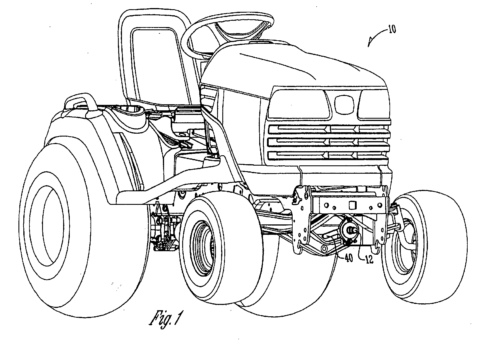
- FIG. 1 taken in which a lawn tractor or a vehicle 10 is shown becomes.
- a PTO shaft 12 with a front end portion 14 and a rear end portion 16.
- the rear end region 16 by a universal joint 18 supported, which is effective on a transmission axis output shaft connection or an output connection 20 attached is.
- the front end portion 14 is supported by a bearing lock collar 22 supported on a means for removing the PTO shaft 12 is attached to a console 24 Allow removal of the PTO shaft 12.
- the console 24 is in the Essentially L-shaped with a semicircular recess 26 and receiving recesses 28 which are in corresponding shoulders 30 of the console 24 are provided (see FIGS. 3 and 4), educated.
- a bearing flange 32 is secured to a bearing 34.
- the Bearing flange 32 is a plate 36 with a central opening 38 and a handle 40 connected.
- the bearing flange 32 and the Plate 36 are by shoulder screws 42 and nuts 44th connected.
- the shoulder screws 42 have a head 46, one Shoulder area 48 and a shaft 50.
- a lock 52 with a first, a through hole 56 having flange 54 and with a second flange 58, which extends away from the console 24 are with the lower shoulder of the console 24 by a spring-loaded Pin 60 connected.
- An end portion of the flange 54 is bent with respect to the orientation of the through hole 56 and forms a flange 55 (Figs. 5 and 6) which is at an angle of forms about 20 ° with the flange 54. Occurs when assembling the Head 46 of the screw 42 with the flange 55 in engagement, so this pushed outward so that the flange 54 with respect Fig. 4 tilts to the left and the shoulder 48 of the screw 42 in the bore 56 slides and is received by this.
- the Flange 54 then jumps into its due to the spring force Starting position back.
- the shoulder screws 42 fit which connect the bearing flange 32 and the plate 36, in the Receiving cutouts 28 of the console 24.
- the first flange 54 the latch 52 takes the head 46 of the lower one Shoulder bolt 42 in the bore 56.
- the spring-loaded Pin 60 which extends through a recess 61 for connection to the bracket 54 extends, holds the first flange 54 in one Position in which the head 46 of the shoulder screw 42 in the Bore 56, as shown in Fig. 2, is received. In this position, the latch 52 holds the plate 36 in Connection to the console 24.
- the handle 40 is used to the components from the position in Fig. 2 in the position in Fig. 4, and vice versa, to move.
- the second flange 58 of the latch 52 exerted force so that the latch 52 pivoted about the spring-loaded pin 60 and the first Flange 54 moves outward from the bracket 24 as seen on Best of Fig. 4 can be seen. If the lock 52 is in this position, it gives the plate 36 of the console 24 free to remove the PTO 12 from the Console 24 and then allow a forward pull to do that Universal joint 18 from the output connection 20 of a rotary drive source (not shown) on the vehicle 10 to separate. As shown by this description removing the PTO 12 from the front of the Made of vehicle 10 and does not require the use of Tools.
- This invention eliminates the need to a locking collar on the universal joint 18 pull backwards, which is at the exit connection is attached to remove the PTO.
- the present invention aims to provide a device for To provide a PTO easily without tools to remove which is a minimal number of components having.
Landscapes
- Engineering & Computer Science (AREA)
- Life Sciences & Earth Sciences (AREA)
- Mechanical Engineering (AREA)
- Soil Sciences (AREA)
- Environmental Sciences (AREA)
- Chemical & Material Sciences (AREA)
- Combustion & Propulsion (AREA)
- Transportation (AREA)
- Agricultural Machines (AREA)
- Harvester Elements (AREA)
Abstract
Fahrzeug, insbesondere Fahrzeuge zur Rasen-, Garten- und Grundstückspflege, welche an ihrer Vorderseite mit antreibbaren Anbaugeräten ausgestattet werden können, weisen eine Zapfwelle auf, die sich von dem Fahrzeug aus gesehen, nach vorn erstreckt. Derartige Fahrzeuge bzw. Rasentraktoren mit Zapfwellen, welche sich nach vorn erstrecken sind bekannt; jedoch muss die Zapfwelle meist abgenommen werden, wenn ein Mähwerk verwendet werden soll.Vehicle, especially vehicles for lawn, garden and Plot maintenance, which can be driven at the front Attachments can be equipped, have a PTO on, as seen from the vehicle, forward extends. Such vehicles or lawn tractors with PTO shafts which extend forward are known; however, the PTO usually has to be removed when a Mower to be used.
Es wird ein Fahrzeug (10), insbesondere ein Fahrzeug zur
Rasen-, Garten- und Grundstückspflege, mit einer abnehmbaren
Zapfwelle (12) vorgeschlagen, welche ohne einen Einsatz von
Werkzeugen an das Fahrzeug (10) an- und abgebaut werden kann.
Darüber hinaus wird eine Zapfwelle (12) vorgeschlagen, welche
an die Verwendung an einem solchen Fahrzeug (10) angepasst ist.
Description
Die Erfindung betrifft eine Zapfwelleneinrichtung sowie ein Fahrzeug zur Rasen-, Garten- und Grundstückspflege mit einer Zapfwelleneinrichtung.The invention relates to a PTO device and a Vehicle for lawn, garden and property maintenance with one PTO facility.
Fahrzeug, insbesondere Fahrzeuge zur Rasen-, Garten- und Grundstückspflege, welche an ihrer Vorderseite mit antreibbaren Anbaugeräten ausgestattet werden können, weisen eine Zapfwelle auf, die sich von dem Fahrzeug aus gesehen, nach vorn erstreckt. Derartige Fahrzeuge bzw. Rasentraktoren mit Zapfwellen, welche sich nach vorn erstrecken, sind bekannt; jedoch muss die Zapfwelle meist abgenommen werden, wenn ein Mähwerk verwendet werden soll.Vehicle, especially vehicles for lawn, garden and Plot maintenance, which can be driven at the front Attachments can be equipped, have a PTO on, as seen from the vehicle, forward extends. Such vehicles or lawn tractors with PTO shafts that extend forward are known; however, the PTO usually has to be removed when a Mower to be used.
Eine bekannte Zapfwelle weist eine Sechskantwelle auf, welche bei einem Abnehmen von dem Fahrzeug aus ihrem Lager herausgleiten kann. Derartige Zapfwellen sind jedoch schwierig zu entfernen und erfordern die Verwendung von Werkzeugen. Darüber hinaus kann es vorkommen, dass sie durch Schmutz und Rost blockiert werden.A known PTO shaft has a hexagonal shaft, which when the vehicle is removed from its warehouse can slide out. However, such PTOs are difficult to remove and require the use of tools. In addition, they can be dirty and dirty Rust can be blocked.
Das der Erfindung zugrunde liegende Problem wird in der schwierigen Handhabung bekannter Zapfwellen gesehen.The problem underlying the invention is in the difficult handling of known PTOs.
Dieses Problem wird erfindungsgemäß durch die Lehre der Patentansprüche 1 bzw. 6 gelöst, wobei in den weiteren Patentansprüchen die Lösung in vorteilhafter Weise weiterentwickelnde Merkmale aufgeführt sind.This problem is solved according to the invention by the teaching of the claims 1 and 6 solved, wherein in the further claims further developing the solution in an advantageous manner Features are listed.
Auf diese Weise wird eine abnehmbare Zapfwelle zur Verfügung gestellt, deren rückwärtiger Endbereich durch ein Kreuzgelenk mit einer Ausgangswelle einer Getriebeachse eines Fahrzeugs verbunden werden kann. Ein vorderer Endbereich wird durch ein Lager abgestützt, das an Mitteln zum Abnehmen der Zapfwelle von der Konsole, welche mit einem vorderen Bereich des Fahrzeugs zum Entfernen der Zapfwelle verbunden ist, vorgesehen ist. Die Mittel zum Abnehmen der Zapfwelle weisen eine Platte, welche abnehmbar mit der Konsole verbunden ist, und eine Verriegelung auf, die mit der Konsole derart zusammenwirkt, dass die Platte in einer ersten Stellung mit der Konsole verbunden hält und in einer zweiten Stellung die Platte freigibt.In this way, a removable PTO is available posed, the rear end region by a universal joint with an output shaft of a transmission axis of a vehicle can be connected. A front end area is marked by a Bearing supported on means for removing the PTO from the console, which connects to a front area of the vehicle is connected to remove the PTO is provided. The PTO removal means comprise a plate which is detachably connected to the console, and a latch that interacts with the console in such a way that the plate holds in a first position connected to the console and in a second position releases the plate.
In der Zeichnung ist ein nachfolgend näher beschriebenes Ausführungsbeispiel der Erfindung dargestellt. Es zeigt:
- Fig. 1
- eine perspektivische Ansicht eines als Rasentraktor ausgeführten Fahrzeugs von vorn betrachtet,
- Fig. 2
- eine rückwärtige Seitenansicht einer Zapfwelle des Fahrzeugs,
- Fig. 3
- eine Explosionsdarstellung der Zapfwelle, einer zugehörigen Konsole sowie eines Lagers,
- Fig. 4
- eine vergrößerte rückwärtige Ansicht der Zapfwelle und der Konsole,
- Fig. 5
- eine vergrößerte Darstellung einer Verriegelungseinrichtung,
- Fig. 6
- eine perspektivische Darstellung der Verriegelungseinrichtung entsprechend Fig. 5 und
- Fig. 7
- eine vergrößerte perspektivische Darstellung entsprechend Fig. 4 von unten betrachtet.
- Fig. 1
- 3 shows a perspective view of a vehicle designed as a lawn tractor viewed from the front,
- Fig. 2
- a rear side view of a PTO of the vehicle,
- Fig. 3
- an exploded view of the PTO, an associated bracket and a bearing,
- Fig. 4
- an enlarged rear view of the PTO and the bracket,
- Fig. 5
- an enlarged view of a locking device,
- Fig. 6
- a perspective view of the locking device corresponding to FIGS. 5 and
- Fig. 7
- an enlarged perspective view corresponding to FIG. 4 viewed from below.
Es wird Bezug auf die Zeichnungen und insbesondere auf Fig. 1
genommen, in der ein Rasentraktor bzw. ein Fahrzeug 10 gezeigt
wird. Zwischen vorderen und rückwärtigen Endbereichen des
Fahrzeugs 10 erstreckt sich eine Zapfwelle 12 mit einem
vorderen Endbereich 14 und einem rückwärtigen Endbereich 16.
Wie es am Besten in Fig. 2 gesehen werden kann, wird der
rückwärtige Endbereich 16 durch einen Kreuzgelenk 18
abgestützt, welcher wirksam an einer Getriebeachsenausgangswellenverbindung
bzw. einer Ausgangsverbindung 20 angebracht
ist.Reference is made to the drawings and in particular to FIG. 1
taken in which a lawn tractor or a
Der vordere Endbereich 14 wird durch eine Lagerverriegelungsmanschette
22 abgestützt, die an einem Mittel zum Abnehmen der
Zapfwelle 12 von einer Konsole 24 angebracht ist, um ein
Entfernen der Zapfwelle 12 zu erlauben. Die Konsole 24 ist im
Wesentlichen L-förmig mit einer halbkreisförmigen Aussparung 26
und Aufnahmeaussparungen 28, welche in entsprechenden Schultern
30 der Konsole 24 vorgesehen sind (siehe Fig. 3 und 4),
ausgebildet.The front end portion 14 is supported by a
Ein Lagerflansch 32 ist an einem Lager 34 gesichert. Mit dem
Lagerflansch 32 ist eine Platte 36 mit einer zentralen Öffnung
38 und einem Griff 40 verbunden. Der Lagerflansch 32 und die
Platte 36 sind durch Schulterschrauben 42 und Muttern 44
verbunden. Die Schulterschrauben 42 weisen einen Kopf 46, einen
Schulterbereich 48 und einen Schaft 50 auf.A
Eine Verriegelung 52 mit einem ersten, eine Durchgangsbohrung
56 aufweisenden Flansch 54 und mit einem zweiten Flansch 58,
der sich von der Konsole 24 weg nach außen erstreckt, sind mit
der unteren Schulter der Konsole 24 durch einen federbelasteten
Stift 60 verbunden. Ein Endbereich des Flansches 54 ist
bezüglich der Ausrichtung der Durchgangsbohrung 56 gebogen und
bildet einen Flansch 55 (Fig. 5 und 6), der einen Winkel von
etwa 20° mit dem Flansch 54 bildet. Tritt bei der Montage der
Kopf 46 der Schraube 42 mit dem Flansch 55 in Eingriff, so wird
dieser nach außen gedrückt, so dass der Flansch 54 hinsichtlich
Fig. 4 nach links kippt und die Schulter 48 der Schraube 42 in
die Bohrung 56 gleitet und von dieser aufgenommen wird. Der
Flansch 54 springt dann infolge der Federkraft in seine
Ausgangsstellung zurück.A
Wenn sie zusammengebaut sind, passen die Schulterschrauben 42,
welche den Lagerflansch 32 und die Platte 36 verbinden, in die
Aufnahmeaussparungen 28 der Konsole 24. Der erste Flansch 54
der Verriegelung 52 nimmt den Kopf 46 des unteren
Schulterbolzens 42 in der Bohrung 56 auf. Der federbelastete
Stift 60, der sich durch eine Aussparung 61 zur Verbindung mit
der Konsole 54 erstreckt, hält den ersten Flansch 54 in einer
Stellung, in der der Kopf 46 der Schulterschraube 42 in der
Bohrung 56, wie dies in Fig. 2 gezeigt wird, aufgenommen wird.
In dieser Stellung hält die Verriegelung 52 die Platte 36 in
Verbindung mit der Konsole 24. Der Griff 40 wird verwendet, um
die Bauteile von der Stellung in Fig. 2 in die Stellung in Fig.
4, und umgekehrt, zu bewegen.When assembled, the shoulder screws 42 fit
which connect the
Um die Zapfwelle 12 zu entfernen, wird auf den zweiten Flansch
58 der Verriegelung 52 Kraft ausgeübt, so dass die Verriegelung
52 um den federbelasteten Stift 60 verschwenkt und der erste
Flansch 54 sich von der Konsole 24 nach außen bewegt, wie es am
Besten aus Fig. 4 gesehen werden kann. Wenn die Verriegelung 52
sich in dieser Stellung befindet, gibt sie die Platte 36 von
der Konsole 24 frei, um ein Entfernen der Zapfwelle 12 von der
Konsole 24 und dann ein Nach-vorn-Ziehen zu erlauben, um das
Kreuzgelenk 18 von der Ausgangsverbindung 20 einer Rotationsantriebsquelle
(nicht gezeigt) an dem Fahrzeug 10 verschiebend
zu trennen. Wie es durch diese Beschreibung gezeigt wird, wird
ein Entfernen der Zapfwelle 12 von der Vorderseite des
Fahrzeugs 10 aus vorgenommen und erfordert keine Verwendung von
Werkzeugen. Diese Erfindung schließt die Notwendigkeit aus, an
einer Verriegelungsmanschette an dem Kreuzgelenk 18 nach
rückwärts zu ziehen, welche an der Ausgangsverbindung
angebracht ist, um die Zapfwelle zu entfernen. Somit erreicht
die vorliegende Erfindung das Ziel, eine Einrichtung zur
Verfügung zu stellen, um eine Zapfwelle leicht ohne Werkzeuge
zu entfernen, welche eine minimale Anzahl von Bauteilen
aufweist. To remove the
Durch die Beschreibung der bevorzugten Ausführungsform wird es offensichtlich, dass verschiedene Veränderungen durchgeführt werden können, ohne von dem Bereich der Erfindung, wie sie durch die folgenden Ansprüche bestimmt wird, abzuweichen.The description of the preferred embodiment will obviously that various changes have been made can be deviated from the scope of the invention as it is determined by the following claims.
Claims (6)
Applications Claiming Priority (2)
| Application Number | Priority Date | Filing Date | Title |
|---|---|---|---|
| US924640 | 2001-08-08 | ||
| US09/924,640 US6533053B2 (en) | 2001-08-08 | 2001-08-08 | Quick detachable drive shaft |
Publications (3)
| Publication Number | Publication Date |
|---|---|
| EP1284097A2 true EP1284097A2 (en) | 2003-02-19 |
| EP1284097A3 EP1284097A3 (en) | 2004-07-21 |
| EP1284097B1 EP1284097B1 (en) | 2006-03-01 |
Family
ID=25450475
Family Applications (1)
| Application Number | Title | Priority Date | Filing Date |
|---|---|---|---|
| EP02017556A Expired - Lifetime EP1284097B1 (en) | 2001-08-08 | 2002-08-07 | Vehicle and pto-device |
Country Status (4)
| Country | Link |
|---|---|
| US (1) | US6533053B2 (en) |
| EP (1) | EP1284097B1 (en) |
| CA (1) | CA2397471C (en) |
| DE (1) | DE50205910D1 (en) |
Families Citing this family (3)
| Publication number | Priority date | Publication date | Assignee | Title |
|---|---|---|---|---|
| US7950171B2 (en) * | 2007-09-11 | 2011-05-31 | Harnischfeger Technologies, Inc. | Electric mining shovel saddle block assembly with adjustable wear plates |
| WO2014039070A1 (en) | 2012-09-04 | 2014-03-13 | Clark Equipment Company | Front power takeoff for utility vehicle |
| JP6133798B2 (en) * | 2014-01-27 | 2017-05-24 | 株式会社クボタ | Work vehicle |
Family Cites Families (18)
| Publication number | Priority date | Publication date | Assignee | Title |
|---|---|---|---|---|
| US1317084A (en) * | 1919-09-23 | Automobile attachment | ||
| US1555715A (en) * | 1923-06-19 | 1925-09-29 | Kominski Michael | Belt attachment for motor vehicles |
| US1538881A (en) * | 1923-12-07 | 1925-05-26 | Ben D Barton | Power attachment for motor vehicles |
| US1665765A (en) * | 1926-02-15 | 1928-04-10 | American Steam Pump Company | Pump attachment for motor vehicles |
| US1983877A (en) * | 1930-12-22 | 1934-12-11 | Caterpillar Tractor Co | Motor vehicle |
| US2027638A (en) * | 1932-10-07 | 1936-01-14 | Forsberg Fredrick | Power take-off |
| CH516429A (en) * | 1970-12-02 | 1971-12-15 | Schilter & Co Maschf | Motorized vehicle |
| AT320325B (en) * | 1972-09-29 | 1975-02-10 | Walterscheid Gmbh Jean | Device for coupling a vehicle, in particular construction or agricultural tractors with a device, trailer or the like. or .. devices and / or trailers with each other |
| DE2320619C3 (en) * | 1973-04-24 | 1980-02-21 | Gutbrod-Werke Gmbh, 6601 Buebingen | Arrangement of a front PTO shaft of a tractor |
| US4517855A (en) * | 1982-07-12 | 1985-05-21 | Deere & Company | Power take-off lever arrangement for a tractor |
| US4621699A (en) * | 1984-08-20 | 1986-11-11 | Simplicity Manufacturing, Inc. | Power takeoff for tractor having parallelogram front wheel suspension |
| GB8623857D0 (en) * | 1986-10-03 | 1986-11-05 | Massey Ferguson Services Nv | Power take-off drive unit |
| JPS63141835A (en) * | 1986-12-03 | 1988-06-14 | Yanmar Diesel Engine Co Ltd | Front pto power take-out device |
| US4763744A (en) * | 1987-01-02 | 1988-08-16 | Mcvicar John A | Power takeoff shaft arrangement for a road vehicle |
| JP2609497B2 (en) * | 1992-11-30 | 1997-05-14 | 自動車部品工業株式会社 | Propeller shaft |
| US5522669A (en) * | 1993-12-13 | 1996-06-04 | Recker; Florian B. | Torque transmitting coupling device |
| US5667330A (en) * | 1995-11-28 | 1997-09-16 | Case Corporation | Quick-connect mechanism for releasably retaining a power take-off shaft within an output shaft hub |
| JP2001018671A (en) * | 1999-07-08 | 2001-01-23 | Kanzaki Kokyukoki Mfg Co Ltd | Motive power take-off device for tractor |
-
2001
- 2001-08-08 US US09/924,640 patent/US6533053B2/en not_active Expired - Lifetime
-
2002
- 2002-08-07 EP EP02017556A patent/EP1284097B1/en not_active Expired - Lifetime
- 2002-08-07 DE DE50205910T patent/DE50205910D1/en not_active Expired - Lifetime
- 2002-08-08 CA CA002397471A patent/CA2397471C/en not_active Expired - Fee Related
Also Published As
| Publication number | Publication date |
|---|---|
| EP1284097A3 (en) | 2004-07-21 |
| US20030029666A1 (en) | 2003-02-13 |
| CA2397471A1 (en) | 2003-02-08 |
| CA2397471C (en) | 2005-10-11 |
| DE50205910D1 (en) | 2006-04-27 |
| EP1284097B1 (en) | 2006-03-01 |
| US6533053B2 (en) | 2003-03-18 |
Similar Documents
| Publication | Publication Date | Title |
|---|---|---|
| DE69909152T2 (en) | Car motor vehicle with telescopic loading arm | |
| EP0976906A2 (en) | Hinge and vehicle | |
| DE10357956B4 (en) | Zugmaulvorrichtung | |
| DE3402065C1 (en) | Protective device to prevent contact with at least one rotating part | |
| DE3873440T2 (en) | VEHICLE FOR GARDENING AND AGRICULTURAL WORK. | |
| DE102015104928A1 (en) | Agricultural trailer and agricultural train | |
| DE112004000916T5 (en) | towing equipment | |
| EP1284374B1 (en) | Tensioning device and working machine, in particular a lawn mower | |
| DE3322551C2 (en) | Intermediate piece for switching off the lateral mobility of the lower links of an agricultural tractor | |
| EP1423999A1 (en) | Attachment, implement or vehicle | |
| DE202009001502U1 (en) | Hand-held implement | |
| EP0254113A2 (en) | Hydraulic steering brake installation for vehicle | |
| EP1284097B1 (en) | Vehicle and pto-device | |
| EP3508397B1 (en) | Device for steering a motor vehicle and intermediate transmission for same | |
| DE69814989T2 (en) | Off-road vehicle with steerable front axle and front PTO clutch | |
| DE927672C (en) | Main pin assembly for an endless link chain, especially for tractor vehicles | |
| EP1284375B1 (en) | Cutter device and method to change its traction means | |
| EP1437273B1 (en) | Connector assembly of a wiper device for windshields of vehicles | |
| DE602006000600T2 (en) | trailer hitch | |
| EP0617882A1 (en) | Device for connecting wheelable argicultural implements to tractors | |
| EP0022283A1 (en) | Device for preventing overstrain of the connection between two parts of an agricultural machine | |
| DE2732345A1 (en) | COUPLING DEVICE | |
| DE3874253T2 (en) | DEVICE FOR CONNECTING THE MOWING MACHINE COMPONENTS TO A HARVESTER. | |
| EP4328051A1 (en) | Ball hitch assembly for an agricultural tractor | |
| DE102008053660B4 (en) | Hub for a fitting of a vehicle seat, fitting for a vehicle seat and shaft-hub assembly for fitting a vehicle seat |
Legal Events
| Date | Code | Title | Description |
|---|---|---|---|
| PUAI | Public reference made under article 153(3) epc to a published international application that has entered the european phase |
Free format text: ORIGINAL CODE: 0009012 |
|
| AK | Designated contracting states |
Designated state(s): AT BE BG CH CY CZ DE DK EE ES FI FR GB GR IE IT LI LU MC NL PT SE SK TR |
|
| AX | Request for extension of the european patent |
Extension state: AL LT LV MK RO SI |
|
| PUAL | Search report despatched |
Free format text: ORIGINAL CODE: 0009013 |
|
| AK | Designated contracting states |
Kind code of ref document: A3 Designated state(s): AT BE BG CH CY CZ DE DK EE ES FI FR GB GR IE IT LI LU MC NL PT SE SK TR |
|
| AX | Request for extension of the european patent |
Extension state: AL LT LV MK RO SI |
|
| RIC1 | Information provided on ipc code assigned before grant |
Ipc: 7B 60K 25/06 B Ipc: 7A 01B 71/06 A |
|
| 17P | Request for examination filed |
Effective date: 20050121 |
|
| AKX | Designation fees paid |
Designated state(s): DE ES FR GB IT |
|
| GRAP | Despatch of communication of intention to grant a patent |
Free format text: ORIGINAL CODE: EPIDOSNIGR1 |
|
| GRAS | Grant fee paid |
Free format text: ORIGINAL CODE: EPIDOSNIGR3 |
|
| GRAA | (expected) grant |
Free format text: ORIGINAL CODE: 0009210 |
|
| AK | Designated contracting states |
Kind code of ref document: B1 Designated state(s): DE ES FR GB IT |
|
| REG | Reference to a national code |
Ref country code: GB Ref legal event code: FG4D Free format text: NOT ENGLISH |
|
| GBT | Gb: translation of ep patent filed (gb section 77(6)(a)/1977) |
Effective date: 20060317 |
|
| REF | Corresponds to: |
Ref document number: 50205910 Country of ref document: DE Date of ref document: 20060427 Kind code of ref document: P |
|
| PG25 | Lapsed in a contracting state [announced via postgrant information from national office to epo] |
Ref country code: ES Free format text: LAPSE BECAUSE OF THE APPLICANT RENOUNCES Effective date: 20060525 |
|
| REG | Reference to a national code |
Ref country code: ES Ref legal event code: FD2A Effective date: 20060525 |
|
| ET | Fr: translation filed | ||
| PLBE | No opposition filed within time limit |
Free format text: ORIGINAL CODE: 0009261 |
|
| STAA | Information on the status of an ep patent application or granted ep patent |
Free format text: STATUS: NO OPPOSITION FILED WITHIN TIME LIMIT |
|
| 26N | No opposition filed |
Effective date: 20061204 |
|
| PGFP | Annual fee paid to national office [announced via postgrant information from national office to epo] |
Ref country code: IT Payment date: 20080825 Year of fee payment: 7 Ref country code: FR Payment date: 20080818 Year of fee payment: 7 |
|
| REG | Reference to a national code |
Ref country code: FR Ref legal event code: ST Effective date: 20100430 |
|
| PG25 | Lapsed in a contracting state [announced via postgrant information from national office to epo] |
Ref country code: FR Free format text: LAPSE BECAUSE OF NON-PAYMENT OF DUE FEES Effective date: 20090831 |
|
| PG25 | Lapsed in a contracting state [announced via postgrant information from national office to epo] |
Ref country code: IT Free format text: LAPSE BECAUSE OF NON-PAYMENT OF DUE FEES Effective date: 20090807 |
|
| PGFP | Annual fee paid to national office [announced via postgrant information from national office to epo] |
Ref country code: DE Payment date: 20140721 Year of fee payment: 13 |
|
| REG | Reference to a national code |
Ref country code: DE Ref legal event code: R119 Ref document number: 50205910 Country of ref document: DE |
|
| PG25 | Lapsed in a contracting state [announced via postgrant information from national office to epo] |
Ref country code: DE Free format text: LAPSE BECAUSE OF NON-PAYMENT OF DUE FEES Effective date: 20160301 |
|
| PGFP | Annual fee paid to national office [announced via postgrant information from national office to epo] |
Ref country code: GB Payment date: 20210827 Year of fee payment: 20 |
|
| REG | Reference to a national code |
Ref country code: GB Ref legal event code: PE20 Expiry date: 20220806 |
|
| PG25 | Lapsed in a contracting state [announced via postgrant information from national office to epo] |
Ref country code: GB Free format text: LAPSE BECAUSE OF EXPIRATION OF PROTECTION Effective date: 20220806 |