EP1284201A2 - Beschichtungsvorrichtung und Verfahren zum Schutz eines aufgezeichneten Produktes durch eine flüssige Beschichtung, und Beschützungsverfahren zu einem aufgezeichneten Produkt - Google Patents
Beschichtungsvorrichtung und Verfahren zum Schutz eines aufgezeichneten Produktes durch eine flüssige Beschichtung, und Beschützungsverfahren zu einem aufgezeichneten Produkt Download PDFInfo
- Publication number
- EP1284201A2 EP1284201A2 EP02017858A EP02017858A EP1284201A2 EP 1284201 A2 EP1284201 A2 EP 1284201A2 EP 02017858 A EP02017858 A EP 02017858A EP 02017858 A EP02017858 A EP 02017858A EP 1284201 A2 EP1284201 A2 EP 1284201A2
- Authority
- EP
- European Patent Office
- Prior art keywords
- coating
- liquid
- protection
- image
- porous layer
- Prior art date
- Legal status (The legal status is an assumption and is not a legal conclusion. Google has not performed a legal analysis and makes no representation as to the accuracy of the status listed.)
- Granted
Links
- 238000000576 coating method Methods 0.000 title claims abstract description 237
- 239000011248 coating agent Substances 0.000 title claims abstract description 232
- 239000007788 liquid Substances 0.000 title claims abstract description 197
- 238000000034 method Methods 0.000 title claims description 36
- 239000000463 material Substances 0.000 claims abstract description 58
- 238000004040 coloring Methods 0.000 claims abstract description 48
- 239000000758 substrate Substances 0.000 claims abstract description 30
- 230000035515 penetration Effects 0.000 claims description 14
- 238000003860 storage Methods 0.000 claims description 14
- 239000010419 fine particle Substances 0.000 claims description 11
- 239000011148 porous material Substances 0.000 claims description 9
- 239000002657 fibrous material Substances 0.000 claims description 7
- 239000002245 particle Substances 0.000 claims description 7
- -1 fatty acid esters Chemical class 0.000 claims description 6
- 235000014113 dietary fatty acids Nutrition 0.000 claims description 5
- 239000000194 fatty acid Substances 0.000 claims description 5
- 229930195729 fatty acid Natural products 0.000 claims description 5
- 229920001296 polysiloxane Polymers 0.000 claims description 5
- 239000003921 oil Substances 0.000 claims description 4
- 229920002545 silicone oil Polymers 0.000 claims description 4
- YCKRFDGAMUMZLT-UHFFFAOYSA-N Fluorine atom Chemical compound [F] YCKRFDGAMUMZLT-UHFFFAOYSA-N 0.000 claims description 2
- 238000007599 discharging Methods 0.000 claims description 2
- 229910052731 fluorine Inorganic materials 0.000 claims description 2
- 239000011737 fluorine Substances 0.000 claims description 2
- 230000035699 permeability Effects 0.000 claims 3
- 239000010410 layer Substances 0.000 description 96
- 230000006866 deterioration Effects 0.000 description 17
- 230000003287 optical effect Effects 0.000 description 16
- 238000012360 testing method Methods 0.000 description 13
- VYPSYNLAJGMNEJ-UHFFFAOYSA-N Silicium dioxide Chemical compound O=[Si]=O VYPSYNLAJGMNEJ-UHFFFAOYSA-N 0.000 description 12
- 239000004744 fabric Substances 0.000 description 10
- PNEYBMLMFCGWSK-UHFFFAOYSA-N aluminium oxide Inorganic materials [O-2].[O-2].[O-2].[Al+3].[Al+3] PNEYBMLMFCGWSK-UHFFFAOYSA-N 0.000 description 9
- 239000011230 binding agent Substances 0.000 description 7
- 239000011521 glass Substances 0.000 description 6
- TWNQGVIAIRXVLR-UHFFFAOYSA-N oxo(oxoalumanyloxy)alumane Chemical compound O=[Al]O[Al]=O TWNQGVIAIRXVLR-UHFFFAOYSA-N 0.000 description 6
- 229920005989 resin Polymers 0.000 description 6
- 239000011347 resin Substances 0.000 description 6
- 239000002585 base Substances 0.000 description 5
- 238000007598 dipping method Methods 0.000 description 5
- 239000000049 pigment Substances 0.000 description 5
- CBENFWSGALASAD-UHFFFAOYSA-N Ozone Chemical compound [O-][O+]=O CBENFWSGALASAD-UHFFFAOYSA-N 0.000 description 4
- TZCXTZWJZNENPQ-UHFFFAOYSA-L barium sulfate Chemical compound [Ba+2].[O-]S([O-])(=O)=O TZCXTZWJZNENPQ-UHFFFAOYSA-L 0.000 description 4
- 230000007547 defect Effects 0.000 description 4
- 238000011156 evaluation Methods 0.000 description 4
- 239000010408 film Substances 0.000 description 4
- 239000007789 gas Substances 0.000 description 4
- GGCZERPQGJTIQP-UHFFFAOYSA-N sodium;9,10-dioxoanthracene-2-sulfonic acid Chemical compound [Na+].C1=CC=C2C(=O)C3=CC(S(=O)(=O)O)=CC=C3C(=O)C2=C1 GGCZERPQGJTIQP-UHFFFAOYSA-N 0.000 description 4
- 238000010521 absorption reaction Methods 0.000 description 3
- 239000012790 adhesive layer Substances 0.000 description 3
- VXAUWWUXCIMFIM-UHFFFAOYSA-M aluminum;oxygen(2-);hydroxide Chemical compound [OH-].[O-2].[Al+3] VXAUWWUXCIMFIM-UHFFFAOYSA-M 0.000 description 3
- 230000015572 biosynthetic process Effects 0.000 description 3
- 229920001577 copolymer Polymers 0.000 description 3
- 244000144992 flock Species 0.000 description 3
- 230000001788 irregular Effects 0.000 description 3
- MWUXSHHQAYIFBG-UHFFFAOYSA-N nitrogen oxide Inorganic materials O=[N] MWUXSHHQAYIFBG-UHFFFAOYSA-N 0.000 description 3
- RKJGFHYCZPZJPE-UHFFFAOYSA-N 2,2-bis(16-methylheptadecanoyloxymethyl)butyl 16-methylheptadecanoate Chemical compound CC(C)CCCCCCCCCCCCCCC(=O)OCC(CC)(COC(=O)CCCCCCCCCCCCCCC(C)C)COC(=O)CCCCCCCCCCCCCCC(C)C RKJGFHYCZPZJPE-UHFFFAOYSA-N 0.000 description 2
- VTYYLEPIZMXCLO-UHFFFAOYSA-L Calcium carbonate Chemical compound [Ca+2].[O-]C([O-])=O VTYYLEPIZMXCLO-UHFFFAOYSA-L 0.000 description 2
- 239000004372 Polyvinyl alcohol Substances 0.000 description 2
- PPBRXRYQALVLMV-UHFFFAOYSA-N Styrene Chemical compound C=CC1=CC=CC=C1 PPBRXRYQALVLMV-UHFFFAOYSA-N 0.000 description 2
- XLOMVQKBTHCTTD-UHFFFAOYSA-N Zinc monoxide Chemical compound [Zn]=O XLOMVQKBTHCTTD-UHFFFAOYSA-N 0.000 description 2
- 239000000654 additive Substances 0.000 description 2
- VSCWAEJMTAWNJL-UHFFFAOYSA-K aluminium trichloride Chemical compound Cl[Al](Cl)Cl VSCWAEJMTAWNJL-UHFFFAOYSA-K 0.000 description 2
- ANBBXQWFNXMHLD-UHFFFAOYSA-N aluminum;sodium;oxygen(2-) Chemical compound [O-2].[O-2].[Na+].[Al+3] ANBBXQWFNXMHLD-UHFFFAOYSA-N 0.000 description 2
- 239000007864 aqueous solution Substances 0.000 description 2
- QVQLCTNNEUAWMS-UHFFFAOYSA-N barium oxide Chemical compound [Ba]=O QVQLCTNNEUAWMS-UHFFFAOYSA-N 0.000 description 2
- 229910001864 baryta Inorganic materials 0.000 description 2
- 239000008119 colloidal silica Substances 0.000 description 2
- 238000009826 distribution Methods 0.000 description 2
- 230000000694 effects Effects 0.000 description 2
- 238000005562 fading Methods 0.000 description 2
- 239000001023 inorganic pigment Substances 0.000 description 2
- 238000011835 investigation Methods 0.000 description 2
- 238000010030 laminating Methods 0.000 description 2
- 230000009965 odorless effect Effects 0.000 description 2
- 229920000642 polymer Polymers 0.000 description 2
- 229920002635 polyurethane Polymers 0.000 description 2
- 239000004814 polyurethane Substances 0.000 description 2
- 229920002451 polyvinyl alcohol Polymers 0.000 description 2
- 230000001681 protective effect Effects 0.000 description 2
- 230000000717 retained effect Effects 0.000 description 2
- 239000000377 silicon dioxide Substances 0.000 description 2
- 229910001388 sodium aluminate Inorganic materials 0.000 description 2
- 229910052815 sulfur oxide Inorganic materials 0.000 description 2
- 229940118594 trimethylolpropane triisostearate Drugs 0.000 description 2
- XLYOFNOQVPJJNP-UHFFFAOYSA-N water Substances O XLYOFNOQVPJJNP-UHFFFAOYSA-N 0.000 description 2
- 239000004925 Acrylic resin Substances 0.000 description 1
- 229920000178 Acrylic resin Polymers 0.000 description 1
- 239000005995 Aluminium silicate Substances 0.000 description 1
- 229920002134 Carboxymethyl cellulose Polymers 0.000 description 1
- VGGSQFUCUMXWEO-UHFFFAOYSA-N Ethene Chemical compound C=C VGGSQFUCUMXWEO-UHFFFAOYSA-N 0.000 description 1
- 239000005977 Ethylene Substances 0.000 description 1
- 108010010803 Gelatin Proteins 0.000 description 1
- 229920000084 Gum arabic Polymers 0.000 description 1
- 239000004354 Hydroxyethyl cellulose Substances 0.000 description 1
- 239000005909 Kieselgur Substances 0.000 description 1
- 239000004677 Nylon Substances 0.000 description 1
- 241000978776 Senegalia senegal Species 0.000 description 1
- 229920002472 Starch Polymers 0.000 description 1
- GWEVSGVZZGPLCZ-UHFFFAOYSA-N Titan oxide Chemical compound O=[Ti]=O GWEVSGVZZGPLCZ-UHFFFAOYSA-N 0.000 description 1
- 239000002250 absorbent Substances 0.000 description 1
- 230000002745 absorbent Effects 0.000 description 1
- 239000000205 acacia gum Substances 0.000 description 1
- 235000010489 acacia gum Nutrition 0.000 description 1
- 229910052782 aluminium Inorganic materials 0.000 description 1
- 235000012211 aluminium silicate Nutrition 0.000 description 1
- DIZPMCHEQGEION-UHFFFAOYSA-H aluminium sulfate (anhydrous) Chemical compound [Al+3].[Al+3].[O-]S([O-])(=O)=O.[O-]S([O-])(=O)=O.[O-]S([O-])(=O)=O DIZPMCHEQGEION-UHFFFAOYSA-H 0.000 description 1
- 239000002518 antifoaming agent Substances 0.000 description 1
- 239000003963 antioxidant agent Substances 0.000 description 1
- 230000003078 antioxidant effect Effects 0.000 description 1
- 239000008346 aqueous phase Substances 0.000 description 1
- 239000012298 atmosphere Substances 0.000 description 1
- 230000005540 biological transmission Effects 0.000 description 1
- 229910000019 calcium carbonate Inorganic materials 0.000 description 1
- 239000001768 carboxy methyl cellulose Substances 0.000 description 1
- 235000010948 carboxy methyl cellulose Nutrition 0.000 description 1
- 229920003090 carboxymethyl hydroxyethyl cellulose Polymers 0.000 description 1
- 239000008112 carboxymethyl-cellulose Substances 0.000 description 1
- 239000001913 cellulose Substances 0.000 description 1
- 229920002678 cellulose Polymers 0.000 description 1
- 239000000919 ceramic Substances 0.000 description 1
- 238000006243 chemical reaction Methods 0.000 description 1
- 239000003795 chemical substances by application Substances 0.000 description 1
- 239000004927 clay Substances 0.000 description 1
- 229910052570 clay Inorganic materials 0.000 description 1
- 239000000470 constituent Substances 0.000 description 1
- 239000013078 crystal Substances 0.000 description 1
- GHVNFZFCNZKVNT-UHFFFAOYSA-M decanoate Chemical compound CCCCCCCCCC([O-])=O GHVNFZFCNZKVNT-UHFFFAOYSA-M 0.000 description 1
- 238000011161 development Methods 0.000 description 1
- 230000018109 developmental process Effects 0.000 description 1
- GDVKFRBCXAPAQJ-UHFFFAOYSA-A dialuminum;hexamagnesium;carbonate;hexadecahydroxide Chemical compound [OH-].[OH-].[OH-].[OH-].[OH-].[OH-].[OH-].[OH-].[OH-].[OH-].[OH-].[OH-].[OH-].[OH-].[OH-].[OH-].[Mg+2].[Mg+2].[Mg+2].[Mg+2].[Mg+2].[Mg+2].[Al+3].[Al+3].[O-]C([O-])=O GDVKFRBCXAPAQJ-UHFFFAOYSA-A 0.000 description 1
- 125000000118 dimethyl group Chemical group [H]C([H])([H])* 0.000 description 1
- 238000002845 discoloration Methods 0.000 description 1
- 239000002270 dispersing agent Substances 0.000 description 1
- 229920001971 elastomer Polymers 0.000 description 1
- 239000006081 fluorescent whitening agent Substances 0.000 description 1
- 229920000159 gelatin Polymers 0.000 description 1
- 239000008273 gelatin Substances 0.000 description 1
- 235000019322 gelatine Nutrition 0.000 description 1
- 235000011852 gelatine desserts Nutrition 0.000 description 1
- 230000007062 hydrolysis Effects 0.000 description 1
- 238000006460 hydrolysis reaction Methods 0.000 description 1
- 229960001545 hydrotalcite Drugs 0.000 description 1
- 229910001701 hydrotalcite Inorganic materials 0.000 description 1
- 235000019447 hydroxyethyl cellulose Nutrition 0.000 description 1
- 239000001866 hydroxypropyl methyl cellulose Substances 0.000 description 1
- 229920003088 hydroxypropyl methyl cellulose Polymers 0.000 description 1
- 235000010979 hydroxypropyl methyl cellulose Nutrition 0.000 description 1
- UFVKGYZPFZQRLF-UHFFFAOYSA-N hydroxypropyl methyl cellulose Chemical compound OC1C(O)C(OC)OC(CO)C1OC1C(O)C(O)C(OC2C(C(O)C(OC3C(C(O)C(O)C(CO)O3)O)C(CO)O2)O)C(CO)O1 UFVKGYZPFZQRLF-UHFFFAOYSA-N 0.000 description 1
- 238000005470 impregnation Methods 0.000 description 1
- 230000000977 initiatory effect Effects 0.000 description 1
- NLYAJNPCOHFWQQ-UHFFFAOYSA-N kaolin Chemical compound O.O.O=[Al]O[Si](=O)O[Si](=O)O[Al]=O NLYAJNPCOHFWQQ-UHFFFAOYSA-N 0.000 description 1
- 238000003475 lamination Methods 0.000 description 1
- 239000000314 lubricant Substances 0.000 description 1
- 238000012423 maintenance Methods 0.000 description 1
- 230000014759 maintenance of location Effects 0.000 description 1
- FPYJFEHAWHCUMM-UHFFFAOYSA-N maleic anhydride Chemical compound O=C1OC(=O)C=C1 FPYJFEHAWHCUMM-UHFFFAOYSA-N 0.000 description 1
- 238000004519 manufacturing process Methods 0.000 description 1
- 229910052751 metal Inorganic materials 0.000 description 1
- 239000002184 metal Substances 0.000 description 1
- 150000002739 metals Chemical class 0.000 description 1
- 238000002156 mixing Methods 0.000 description 1
- 239000003607 modifier Substances 0.000 description 1
- 238000006386 neutralization reaction Methods 0.000 description 1
- 229920001778 nylon Polymers 0.000 description 1
- 239000012788 optical film Substances 0.000 description 1
- 239000012860 organic pigment Substances 0.000 description 1
- 239000003002 pH adjusting agent Substances 0.000 description 1
- 239000002304 perfume Substances 0.000 description 1
- 230000000704 physical effect Effects 0.000 description 1
- 229920001200 poly(ethylene-vinyl acetate) Polymers 0.000 description 1
- 229920000036 polyvinylpyrrolidone Polymers 0.000 description 1
- 239000001267 polyvinylpyrrolidone Substances 0.000 description 1
- 235000013855 polyvinylpyrrolidone Nutrition 0.000 description 1
- 238000003825 pressing Methods 0.000 description 1
- 230000002265 prevention Effects 0.000 description 1
- 239000011241 protective layer Substances 0.000 description 1
- 239000007787 solid Substances 0.000 description 1
- 239000008107 starch Substances 0.000 description 1
- 235000019698 starch Nutrition 0.000 description 1
- XTQHKBHJIVJGKJ-UHFFFAOYSA-N sulfur monoxide Chemical class S=O XTQHKBHJIVJGKJ-UHFFFAOYSA-N 0.000 description 1
- 239000002344 surface layer Substances 0.000 description 1
- 239000004094 surface-active agent Substances 0.000 description 1
- 239000000454 talc Substances 0.000 description 1
- 229910052623 talc Inorganic materials 0.000 description 1
- 239000002562 thickening agent Substances 0.000 description 1
- OGIDPMRJRNCKJF-UHFFFAOYSA-N titanium oxide Inorganic materials [Ti]=O OGIDPMRJRNCKJF-UHFFFAOYSA-N 0.000 description 1
- 229920006163 vinyl copolymer Polymers 0.000 description 1
- 229920003169 water-soluble polymer Polymers 0.000 description 1
- 238000004383 yellowing Methods 0.000 description 1
- 239000011787 zinc oxide Substances 0.000 description 1
Images


Classifications
-
- B—PERFORMING OPERATIONS; TRANSPORTING
- B41—PRINTING; LINING MACHINES; TYPEWRITERS; STAMPS
- B41M—PRINTING, DUPLICATING, MARKING, OR COPYING PROCESSES; COLOUR PRINTING
- B41M5/00—Duplicating or marking methods; Sheet materials for use therein
-
- B—PERFORMING OPERATIONS; TRANSPORTING
- B41—PRINTING; LINING MACHINES; TYPEWRITERS; STAMPS
- B41M—PRINTING, DUPLICATING, MARKING, OR COPYING PROCESSES; COLOUR PRINTING
- B41M7/00—After-treatment of prints, e.g. heating, irradiating, setting of the ink, protection of the printed stock
- B41M7/0027—After-treatment of prints, e.g. heating, irradiating, setting of the ink, protection of the printed stock using protective coatings or layers by lamination or by fusion of the coatings or layers
Definitions
- the present invention relates to coating apparatus (for example, coating implements, coating device, etc.) of a liquid for protecting recorded products obtained by, for example, an ink-jet recording method or the like, a coating method of the liquid for protecting the recorded products on the recorded products and a process for protecting the recorded products.
- coating apparatus for example, coating implements, coating device, etc.
- Ink-jet recording apparatus have permitted not only printing of text such as characters on paper, but also photograph-like printing by the technical developments as to formation of fine droplets and multi-gradation in recent years.
- their application fields have been widened under the circumstances, since output and printing like displays have now become feasible as to not only text and designs, but also photograph-like printed articles and graphic arts because of spread of digital cameras.
- the shelf stability and the elongation of shelf life of an image in such a recorded product have become problems to be solved.
- good coloring is achieved in a printed article obtained by using a dye ink on a proper medium (recording medium)
- the durability and shelf stability of image may become poor in some cases.
- a printed article obtained by using a pigment ink may become poor in coloring and rub-off resistance of image under the circumstances though the shelf stability is excellent.
- a countermeasure which may be taken in view of the shelf stability of image is to achieve printing high in durability with a pigment.
- Another countermeasure is to protect a coloring material low in durability such as a dye.
- methods of the protection have been known a method of laminating an image with a protective layer or sheet of a film-forming resin, for example, an acrylic resin to protect it.
- the conventional protecting methods by covering with glass or lamination with a resin have sacrificed a feeling of image quality that directly enjoys an image and so to say, protecting methods by which the image is viewed through a film or glass, namely, the image is observed apart from the naked image.
- the present inventors have researched as to the direct maintenance of a naked image at a high shelf life without sacrificing the image quality due to interposition of a visible transparent layer, thus leading to completion of the present invention.
- the present invention aims at filling voids left in a receiving layer after recording in such a system that a coloring material applied to the receiving layer clearly develops a color, thereby removing sites of a deterioration reaction of the coloring material.
- a liquid for protection low in viscosity when used, penetration becomes quick, and the liquid is easy to be applied.
- the liquid In order to leave a liquid for protection in the receiving layer, however, it is necessary for the liquid to have a moderately high viscosity.
- implements and devices for uniformly applying the liquid are extremely useful. Namely, the present invention has been completed with the object of uniformly applying an intended amount of a liquid with no defect on an image surface even when the viscosity of the liquid is high.
- a coating implement for applying a nonvolatile liquid for protection treatment to a recorded product which is provided with a porous layer as an ink-receiving layer on the surface of a substrate and on which an image has been formed with a coloring material adsorbed on at least the porous layer to protect the image, the liquid not dissolving the coloring material, wherein a coating surface of the implement for applying the liquid to the porous layer having the image is supported by a supporting member, and the coating surface can hold the liquid.
- kits for protection treatment of a recorded product which is provided with a porous layer as an ink-receiving layer on the surface of a substrate and on which an image has been formed with a coloring material adsorbed on at least the porous layer, said kit comprising a container which can hold a nonvolatile liquid which does not dissolve the coloring material, the coating implement described above and a supporting table for supporting the recorded product.
- a coating device for protection treatment of a recorded product which is provided with a porous layer as an ink-receiving layer on the surface of a substrate and on which an image has been formed with a coloring material adsorbed on at least the porous layer
- said coating device comprising a storage part which can store a nonvolatile liquid which does not dissolve the coloring material, a coating member which has a coating surface for coating the image with the liquid provided on an outer periphery of a shaft member and is supported rotatably on the shaft member, a moving means for moving the recorded product relatively to the coating surface while bringing the image surface of the recorded product into contact with the coating surface, and a means for feeding the liquid stored in the storage part to the coating surface of the coating member.
- a coating implement for protection treatment of a recorded product which is provided with a porous layer as an ink-receiving layer on the surface of a substrate and on which an image has been formed with a coloring material adsorbed on at least the porous layer, said coating implement comprising a storage part which can store a nonvolatile liquid which does not dissolve the coloring material, and a coating surface which communicates with the storage part and through which the liquid fed from the storage part can seep.
- kits for protection treatment of an image of a recorded product which is provided with a porous layer as an ink-receiving layer on the surface of a substrate and on which the image has been formed with a coloring material adsorbed on at least the porous layer, said kit comprising the coating implement described above and a supporting table for supporting the recorded product.
- a coating device for protection treatment of an image of a recorded product which is provided with a porous layer as an ink-receiving layer on the surface of a substrate and on which the image has been formed with a coloring material adsorbed on at least the porous layer
- said coating device comprising a container part which can contain a nonvolatile liquid, which does not dissolve the coloring material, in a closed state, an introduction port for introducing the recorded product into the container part, and a takeoff port for discharging the recorded product from the interior of the container part, wherein the introduction and takeoff ports have such a structure that the ports can open upon passage of the recorded product, and a removing means for removing an excess liquid attached to the surface of the recorded product upon passage of the recorded product is provided at the takeoff port.
- a process for protecting a recorded product which is provided with a porous layer as an ink-receiving layer on the surface of a substrate and on which an image has been formed with a coloring material adsorbed on at least the porous layer, said process comprising the step of applying a nonvolatile liquid for protection, which does not dissolve the coloring material, in an excessive amount more than an amount necessary for filling voids in the porous layer to the porous layer, on which the image has been formed, to fill the voids in the porous layer with the liquid for protection.
- the protection treatment of an image of a recorded product can be performed in brief and with good operating ability to directly enjoy the naked image protected.
- a recorded product, to which a protection treatment according to the present invention is applied is obtained by applying an ink comprising a coloring material to a recording medium having a porous layer as an ink-receiving layer to form an image. Since a protection treatment according to the present invention is conducted by impregnating the recorded product with a liquid such as a silicone oil or fatty acid ester, it is preferable to use a recording medium which undergoes no strike-through, for example, a recording medium by which recording is conducted by causing a coloring material such as a dye or pigment to be adsorbed on at least fine particles forming a porous structure of an ink-receiving layer provided on a substrate.
- the recording medium of such a structure is particularly suitable for use in recording using an ink-jet method.
- a recording medium for ink-jet is preferably of the so-called absorption type in which an ink is absorbed in voids formed in the ink-receiving layer on the substrate.
- the absorption type ink-receiving layer can be formed as a porous layer composed mainly of fine particles and containing a binder and other additives as needed.
- the fine particles include inorganic pigments such as silica, clay, talc, calcium carbonate, kaolin, aluminum oxide such as alumina or alumina hydrate, diatomaceous earth, titanium oxide, hydrotalcite and zinc oxide; and organic pigments such as urea-formalin resins, ethylene resins and styrene resins. At least one of these pigments is used.
- the binder preferably used include water-soluble polymers and latexes.
- Examples thereof include polyvinyl alcohol or modified products thereof, starch or modified products thereof, gelatin or modified products thereof, gum arabic, cellulose derivatives such as carboxymethyl cellulose, hydroxyethyl cellulose and hydroxypropylmethyl cellulose, vinyl copolymer latexes such as SBR latexes, NBR latexes, methyl methacrylate-butadiene copolymer latexes, functional-group-modified polymer latexes and ethylene-vinyl acetate copolymers, polyvinyl pyrrolidone, maleic anhydride polymers or copolymers thereof, acrylic ester copolymers, and the like. Two or more of these binders may be used in combination as needed.
- additives may also be used.
- a dispersing agent, thickener, pH adjuster, lubricant, flowability modifier, surfactant, antifoaming agent, parting agent, fluorescent whitening agent, ultraviolet absorbent, antioxidant and the like may be used as needed.
- a particularly preferable recording medium is such that an ink-receiving layer is formed mainly of fine particles having an average particle diameter of at most 10 ⁇ m, preferably at most 1 ⁇ m as the above-described fine particles.
- fine particles are particularly preferred fine silica or aluminum oxide particles.
- the reason why the fine aluminum oxide or silica particles are particularly effective is considered to as follows. Namely, it is considered that although a coloring material adsorbed on the fine aluminum oxide or silica particles is found to greatly undergo color fading by gases such as NOx, SOx and ozone, these particles are liable to attract gases, and so the gases come to be present in the vicinity of the coloring material, and the coloring material is easy to cause color fading.
- fine silica particles are preferred fine silica particles typified by colloidal silica.
- the colloidal silica itself may be available from the market.
- coarse examples thereof may be mentioned those described in, for example, Japanese Patent registration Nos. 2803134 and 2881847.
- fine aluminum oxide particles may be mentioned fine alumina hydrate particles.
- mH 2 O represents an aqueous phase which does not participate in the formation of a crystal lattice, but is able to be eliminated. Therefore, m may take a value other than an integer. When this kind of a material is heated, m may reach a value of 0.
- the alumina hydrate can be generally produced in accordance with the publicly known process such as such hydrolysis of an aluminum alkoxide or sodium aluminate as described in U.S. Patent Nos. 4,242,271 and 420,2870, or a process in which an aqueous solution of aluminum sulfate, aluminum chloride or the like is added to an aqueous solution of sodium aluminate to conduct neutralization as described in Japanese Patent Publication No. 57-44605.
- An ink-jet recording medium using such an alumina hydrate is most suitable for application of the protection process according to the present invention because it is excellent in affinity for the liquid for protection, absorbency and fixing ability, and moreover properties necessary to realize such photograph-like image quality as described above, such as transparency, glossiness and fixing ability of a coloring material such as a dye in a recording liquid are achieved.
- the mixing ratio by weight of the fine particles to the binder is preferably within a range of from 1:1 to 100:1. When the amount of the binder is controlled within the above range, a pore volume optimum for impregnation of the liquid for protection into the ink-receiving layer can be retained.
- the content of the fine aluminum oxide particles or fine silica particles in the ink-receiving layer is preferably at least 50 % by weight, more preferably at least 70 % by weight, most preferably not lower than 80 % by weight, but not higher than 99 % by weight.
- the coating weight of the ink-receiving layer is preferably at least 10 g/m 2 , most preferably 10 to 30 g/m 2 in terms of dry solids from the viewpoints of making the impregnating ability of an image fastness improver good.
- any substrate may be used so far as an ink-receiving layer containing such fine particles as described above can be formed thereon, and stiffness enough to be conveyable by a conveying mechanism in an ink-jet printer or the like is given.
- Paper suitably sized on at least a side on which the ink-receiving layer will be formed, and those (for example, baryta paper) having, at their surfaces, a close porous layer (the so-called baryta layer) formed by applying an inorganic pigment such as barium sulfate together with the binder on to a fibrous substrate may be particularly preferably used as substrates.
- occurrence of surface stickiness due to bleed of a fastness improver on the surface of a recorded product subjected to a fastness-improving treatment can be extremely effectively prevented even when the recorded product is left to stand for a long period of time under a high-temperature and high-humidity environment, and a recorded product far excellent in shelf stability can also be provided.
- the form having a porous layer at a surface layer in a recording medium is not limited to the formation of the porous ink-receiving layer on the substrate, and Alumite or the like may also be used.
- the liquid for protection of a recorded product used in the present invention may be used those which neither dissolve a coloring material applied to the porous layer of the recording medium therein nor affect an image fixed and are nonvolatile, and hence have an effect of protecting the coloring material by filling such a liquid into voids in the porous layer to improve the durability and the like of the image.
- a colorless transparent liquid which does not affect the color tone and the like of the image and improves the image quality by its filling into voids in the porous layer is excellent in general-purpose properties.
- a colored liquid may also be used in some cases.
- the liquid for protection is high in general-purpose properties when it is odorless, a perfume base or the like may be added to the liquid within limits not affecting the image to give a smell suitable for the image.
- liquid for protection may be used at least one selected from, for example, fatty acid esters, silicone oils, modified silicones and fluorine-containing oils.
- the liquid for protection can be held by a coating implement or a coating means of a coating device and has moderate penetrability into the porous layer.
- a liquid having a viscosity of about 10 to 600 Cs is preferred.
- the viscosity is at least 20 Cs in particular, the liquid for protection is surely held by the recorded product.
- the viscosity is at most 300 Cs, the liquid for protection is easier to apply, and evener coating can be performed.
- 20 to 300 Cs may be said to be a particularly preferable viscosity range from the viewpoints of the retention of the liquid for protection in the recorded product and operating ability upon coating.
- a liquid for protection whose viscosity and the like vary with temperature to vary penetrability into the recorded product and malleability or ductility on the surface thereof may also be used.
- a coating operation is performed at a temperature (for example, a temperature higher than room temperature) at which penetrability and malleability or ductility suitable for the coating operation can be achieved, and the temperature of the recorded product is lowered to room temperature after the coating operation, whereby the flowability of the liquid for protection penetrated into the recorded product can be lowered to achieve the flowability that can attain uniform coating.
- the coating of the liquid for protection on the porous layer of the recorded product, on which the coloring material has been fixed is preferably performed in an excessive amount more than an amount necessary for filling voids in the porous layer on which the coloring material has been fixed. It is preferable to remove the liquid for protection from the surface of the porous layer after the voids in the porous layer are sufficiently filled, so as not to form a layer of the liquid for protection on the porous layer.
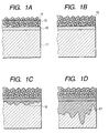
- FIGS. 1A to 1D The states in which such a liquid for protection has been applied to a recorded product are schematically illustrated in section in FIGS. 1A to 1D.
- reference numerals 11, 12 and 13 designate a base paper, a reflection layer and a receiving layer, respectively.
- FIGS. 1A, 1B, 1C and 1D indicate the states in which the coating weight is insufficient, moderate, slightly excessive and greatly excessive, respectively.
- the moderate amount means an amount necessary for filling voids in the ink-receiving layer 13 with the liquid.
- the slightly excessive amount means such a required amount that voids in the ink-receiving layer 13 are filled with the liquid, and the liquid gradually reaches the surface of the substrate 11 and wets the surface thereof or penetrates in the vicinity of the surface.
- Reference numerals 14, 15, 16 and 17 indicate the presence distribution of the liquid for protection in a sectional direction in the respective states.
- the optical density (OD) of the image was lowered by irregular reflection, improvement in durability was not observed, and irregularities appeared in the penetration portions of the liquid with time. Thus, such a state is not preferable.
- the results were such that the optical density (OD) is increased, the image becomes clear, and the durability also becomes excellent.
- FIG. 1D in which the liquid penetrates up to the deep portion of the substrate, both optical density (OD) and durability were excellent, but spots may be observed in some cases in white images.
- the final state of the whole medium surface becomes such a state that the oil is filled into the receiving layer alone as illustrated in FIG. 1B or into the receiving layer and a part of the substrate as illustrated in FIG. 1C.
- An ink-jet printer (BJF870, trade name, manufactured by Canon Inc.) was used to print a photograph-like image on a recoding medium with pseudoboehmite contained in a receiving layer.
- the recording medium is obtained by providing a reflection layer (layer of BaSO 4 ; layer thickness: about 15 ⁇ m) and a receiving layer (binder: PVA) composed of pseudoboehmite type alumina of about 30 ⁇ m on a base paper (substrate). Recording was conducted on this recording media with an ink for the above-described printer. As a result, a coloring material was adsorbed on the receiving layer containing the alumina to form an image. Voids were still left in the receiving layer after the recording.
- a transparent odorless fatty acid ester trimethylolpropane triisostearate represented by the following structural formula; viscosity: 200 Cs
- This liquid was applied in an excessive amount more than an amount necessary for filling voids in the ink-receiving layer to the whole surface of the recorded product obtained above, on which the image has been formed. After the recorded product was left to stand for a proper time after the coating, an excess liquid on the surface of the ink-receiving layer was quickly wiped off.
- the relationship between the shelf time and the penetrated amount is shown in Table 1. Incidentally, the penetrated amount was expressed by a measured value of weight increase of the recorded product with time. Time (sec) Weight increase (mg/148 cm 2 ) 0 0 5 290 10 300 30 330 60 360 120 380 600 410
- the shelf time was controlled to prepare various samples with the degree of penetration of the liquid into the ink-receiving layer changed.
- the penetrated states were as schematically illustrated in FIGS. 1A to 1D.
- the amount of the liquid applied, the optical density of the image and the degree of occurrence of "spots" in the recorded product samples after the coating were determined, and an accelerated deterioration test as to light fastness was conducted.
- the results obtained are shown in Table 2. The respective determinations and test were performed under the following respective conditions.
- optical density of each image sample was expressed as OD (optical density) at a black-printed area in the image as measured by means of a reflection densitometer, Macbeth RD-918 (manufactured by Macbeth Company).
- spots may be conspicuous in some cases in a white colored portion of the image or a blank portion represented as a white color.
- Such a recorded product may not be suitable for use applications in which such spots become a problem. Incidentally, such spots caused no problem in a black colored portion.
- ⁇ E in a silver salt photograph as determined for reference was about 0.1, it is inferred from ⁇ E achieved by the coating weight of 2.1 mg/cm 2 or more in this embodiment that the images protected by the protection treatment according to the present invention have durability about twice of the silver salt photograph in exposure to the air. This indicates that when discoloration of the silver salt photograph begins in the exposure to the air for 5 to several tens years, the initial image quality can be enjoyed over a period of time about twice thereof in the image subjected to the protection treatment according to the present invention.
- the above-described protection treatment permitted directly enjoying the image quality over a long period of time without the presence of a protective member such as glass or film.
- the liquid for protection used in EXAMPLE 1 was applied to the image surface of a recorded product by means of a coating implement illustrated in FIG. 2.
- This coating implement 24 comprises a handle 24a, a cylindrical supporting member 24b and a felt 24c installed at the lower surface of the supporting member, and the felt forms a coating surface.
- the liquid for protection was first put into a receiver container 22 from a bottle container 21 to attach the liquid to the coating surface of the coating implement 24.
- the coating implement 24 was moved on the image surface of the recorded product received in a recessed part corresponding to the shape of the recorded product within a holder (supporting table) 23 to apply the liquid in a somewhat excessive amount to the image surface. Thereafter, an excess liquid was wiped off. Since the handle 24a of the coating implement affects workability, its shape was determined by laying stress on "a feeling of grip" and "a feeling of fitness" that are determined by shape, width and thickness.
- felt 24c-2 narrow in width and felt 24c-1 wide in width both in a direction perpendicular to the axial direction of the handle 24a shown in FIGS. 3A and 3C were provided (see FIG. 3A) to conduct coating using the felt 24c-2 narrow in width for small media such as a postal card size and an L-plate size and the felt 24c-1 wide in width for great media such as an A4 size.
- the optical densities (OD) of images were able to be increased by coating of this liquid to provide recorded products excellent in shelf stability. In these recorded products, the images were able to be directly enjoyed.
- the material for forming the coating surface is not limited to felt, and porous materials and fibrous materials composed of sponge formed of polyurethane or the like, clothes, paper materials, ceramics, and glass may be used.
- members forming a smooth surface such as metals, various kinds of resin films and glass may be used as constituent members for the coating surface so far as they can hold the liquid by attachment thereof.
- the image surface of the recorded product does not always form a uniform flat surface, but may somewhat form waviness or irregularities.
- the coating surface is preferably formed of a material deformable corresponding to the irregularities of the image surface.
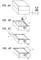
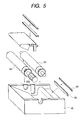
- FIG. 4A The outline of the coating device 40 is illustrated in FIG. 4A, and the parts of the coating device and the manner of assembly are schematically illustrated in FIG. 5.
- FIG. 6 is a cross-sectional view illustrating the mechanism thereof.
- FIGS. 4B to 4D schematically illustrate the manner of use of this device.
- a coating member 63 in this device is constructed as a roller with a layer composed of the material mentioned in EXAMPLE 5 or the like and forming the coating surface formed on an outer periphery of a shaft member and is installed rotatably on the shaft member in a container 40.
- a handle (thumbscrew) 62a extending to the outside of the container from a roller 62 forming a paper feeding means is rotated, whereby rotating operation is transmitted by a gear to rotate the coating member 63 in the prescribed direction, and a liquid 64 is attached to the coating surface of the coating member 63 and applied to the image surface of a recorded product fed there.
- the device is aimed at the form as simple as possible and devised so as to prevent leakage of the liquid, whereby coating by the coating member 63 interlocked with the hand roller 62 and removal of an excess liquid by a blade 65 fixed by a blade presser 66 are conducted.
- a fatty acid ester (trimethylolpropane triisostearate) was used as the liquid like EXAMPLE 1. The rotation was controlled slowly, whereby an excess liquid is wiped off by the blade 65 after 1 to 2 seconds or longer required for the liquid of a high viscosity to penetrate into the receiving layer, and the coating was achieved.
- the optical density (OD) was able to be increased by the coating to provide a recorded product excellent in shelf stability. In this recorded product, the image was able to be directly enjoyed.
- FIG. 7A This embodiment shows an example where a coating implement and a container are united.
- FIG. 7A This set has a holder 73 shown in FIG. 7C and a coating implement 74 shown in FIG. 7B.
- the coating implement 74 has such a structure that a portion 74a combining a handle with a container and a portion composed of a supporting member 74b having a coating surface formed of a porous material 74c such as felt or polyurethane sponge are united.
- the interior of the porous material 74c is formed in such a manner that a liquid contained in the container portion 74a penetrates into the porous material 74c from the inner wall surface thereof so as to seep at the outer wall surface, i.e., the coating surface.
- n When the number of times of the coating is plural times (n times: n > 2), n may be taken into consideration to determine the width to be Wo > V ⁇ T/n. In this case, the penetration time T may be 1 second or shorter. When the time is set to 2 seconds with leeway, however, the moving speed and moving width of the coating implement become 20 mm/sec and 50 mm, respectively. These are substituted into Wo > V ⁇ T to obtain 50 > 20 ⁇ 2. Taking the fact that the number of times of the coating is 2 times into consideration, the respective values are substituted into Wo > V ⁇ T/n to obtain 50 > 20 ⁇ 20/2. Therefore, it is found that the requirements were satisfied with leeway.
- the upper limit of the width of the coating surface composed of the felt or sponge of the coating implement in the moving direction is preset according to requirements such as shape and size required of the coating implement.
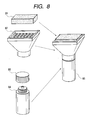
- FIG. 8 The parts of the coating implement and the manner of assembly are schematically illustrated in FIG. 8.
- Reference numeral 81 indicates felt, 82 an intermediate member which supports the felt and feeds the liquid, 83 a lid of a container, 84 a liquid container combining with a holding portion of the coating container, i.e., "grip portion", and 85 a completed state of the coating implement.
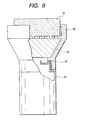
- FIG. 9 is a cross-sectional view of the coating implement illustrating the mechanism thereof.
- Reference numeral 91 indicates felt, 92 a container sheath, 93 a member having pores for holding and feeding the liquid, which is made of sponge or fibrous material, 94 a bolt of the liquid container, and 97 a rubber ring which plays a role of a seal for preventing leakage.
- a coating part is composed of a consumable material so as to exchange it.
- the coating part is preferably composed of soft sponge having fine cells.
- such a material may wear or break in some cases when coating under shear is conducted repeatedly.
- This embodiment took such a constitution that only this part is exchangeable.
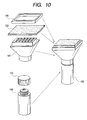
- the frame member 106 has a structure detachable to the support member 101 to make easy to exchange the member 102.
- the container part 104 is detachably connected to the support member 101 by a screw structure.
- a seal member 103 is interposed between these members to prevent leakage of the liquid for protection at the connected site.
- FIG. 11 is a schematic cross-sectional view of the coating implement shown in FIG. 10.
- Alkyl-modified silicone was used as the liquid for protection. Sufficient coating was achieved without insufficient coating like EXAMPLES 5, 6 and 7 by means of an integral container composed of the coating implement and the container, in which the coating part is exchangeable. An excess liquid was then wiped off to test the protecting performance. As a result, the same results as in EXAMPLE 1 were obtained.
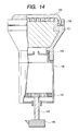
- FIG. 12 The parts of a coating implement 129 according to this embodiment and the manner of assembly are schematically illustrated in FIG. 12, and the structure after assembly is illustrated as a cross-sectional view in FIG. 13. Coating was conducted in the same manner as in EXAMPLES 5, 6, 7 and 8 except that the coating weight of the liquid was controlled to omit the step of wiping off the excess liquid unlike EXAMPLES 5, 6, 7 and 8.
- a container indicated by reference numeral 125 is different from the coating implement shown in FIGS. 10 and 11.
- a fixed amount of the liquid is supplied to the coating surface via a fibrous material or sponge member according to forcing by check valves 137 and 138.
- a container indicated by reference numeral 146 is different from that shown in FIGS. 12 and 13.
- the liquid was fed in a fixed amount according to an angle of rotation by a feed mechanism (147 to 149) by screws to conduct coating.
- a feed mechanism 147 to 149
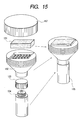
- a preferred coating weight is 0.20 to 0.26 mg/cm 2 , and so it is only necessary to control the coating weight according to the area of the medium so as to fall within the above range.
- FIG. 15 illustrates an example thereof.
- a container 152 having a rectangular felt receiver and a cylindrical lid 157 fixed on the outer periphery of the container by a screw structure are new ideas.
- FIGS. 16A to 16E schematically illustrate this embodiment.
- a coating device used in this embodiment is composed of a holder 161 (FIG. 16C) and a coating implement set 162 (FIG. 16B).
- the coating implement set 162 In the coating implement set 162, are contained a coating implement 163 with sponge fixed to a holding fixture and a container 164 containing a liquid.
- the liquid within the container 164 is poured into a container of the coating implement set 162, the liquid is sufficiently impregnated into the sponge there (see FIG. 16D).
- the liquid is then applied to the surface of an ink-jet recorded product 165 set in the holder 161 using the coating implement (see FIG. 16E).
- This embodiment is related to a process in which coating is performed with the coating implement wide in width without defects, and the liquid is supplied in the container. In this case, both methods of wiping off an excess liquid and applying a proper amount of the liquid to omit the step of wiping may be performed.
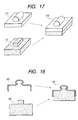
- FIG. 17 illustrates a coating implement for applying an excessive amount of the liquid and then wiping off an excess liquid.
- Reference numeral 171 indicates a handle and a sheath made of a rigid material, 172 sponge, and 173 shows a state after assembly of the handle and a sheath, and the sponge. This sponge has a function of absorbing waviness to apply the liquid even when a medium has waviness, or a place where the medium is placed is not flat and a function of holding the liquid.
- FIG. 18 is a cross-sectional view of the coating implement.
- Reference numeral 181 designates a sheath, 182 sponge, and 183 a state after assembly.
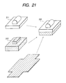
- FIG. 19 illustrates a modified example of the coating implement shown in FIG. 18.
- Reference numeral 191 indicates a sheath. Sponge indicated by reference numeral 192 has the same function as to absorption of waviness as the sponge 182.
- Reference numeral 193 designates a layer for controlling the feed of the liquid, which is low in penetration. Specifically, this layer is composed of an adhesive layer or a layer obtained by collapsing cells.
- Reference numeral 194 indicates a liquid feeding layer in which the amount of the liquid held is determined by a material used and a thickness of the layer. This layer is composed of a thin layer of sponge, felt or fibrous material.
- Reference numeral 195 indicates a state after assembly.
- a flocked fabric was used as the feeding layer.
- Reference numeral 201 designates a sheath, 202 sponge, 203 an adhesive layer, 204 a fabric, and 205 a state after assembly.
- this coating implement the amount of the liquid fed is easy to be controlled, and the matching with the area of a medium can be controlled by the length, material, density and surface characteristics of the flock, and so the tolerance becomes very great, and production is easy.
- a coating surface of 50 mm ⁇ 50 mm was formed by a nylon fabric having a flock of 3 mm to conduct coating. As a result, the coating in a coating weight of 0.2 to 0.3 mg/cm 2 was able to be achieved with good operating ability.
- the coating weight can be controlled by the length and density of the flock that the fabric has, and the area of the coating surface formed thereby. These requirements are suitably selected according to the physical properties of the liquid for protection and the constitution of a medium used in the recorded product, whereby the desired coating weight can be achieved by a simple operation.
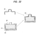
- FIGS. 21 and 22 illustrates a modified example where such a fabric is made exchangeable as a consumable material.
- the coating implement can be used over a long period of time by making the fabric exchangeable.
- Reference numeral 211 designates a sheath, 212 sponge, and 213 a state after assembly.
- Referential numeral 221 designates a cross section of the sheath, 222 a cross section of the sponge, 223 a cross section of the fabric, 224 a cross section of the adhesive layer, and 225 a cross section of the assembled coating implement. In this case, increase of the initial optical density and great improvement in shelf stability are also observed.
- This embodiment is related to a modified example of the coating implement set shown in FIG. 16.
- an absorbing member 231 is contained in a container 162 for the purpose of preventing leakage and making effective use of the liquid. Coating is realized by such a system. A fixed amount of the liquid can be always fed and coated thereby even when the consumption is irregular, and storage of the liquid becomes feasible.
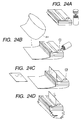
- This embodiment permits dipping.
- a product printed on both sides such as a postal card
- printing is conducted on both sides, and both sides must be protected.
- dipping is an effective coating method.
- a bag forming a container part of a liquid for protection is installed at a supporting member, a recorded product is introduced from an introduction port provided in the supporting member into the bag to dip it in the liquid for protection, and an excess liquid on the surface of the recorded product is wiped off by a blade provided at a takeoff port of the supporting member to remove the recorded product out of the coating implement.
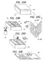
- FIGS. 24A to 24D schematically illustrate a state in which a dipping device composed of a bag 241 and a supporting member is assembled (FIG. 24A), and states in which a liquid is supplied (FIG. 24B), a medium is introduced (FIG. 24C) and the liquid is wiped off and returned (FIG. 24D).
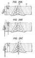
- FIG. 25A illustrates the introduction and takeoff portions thereof in section.
- Reference numeral 251 indicates a sheath, on which the bag is installed.
- Reference numeral 252 designates the introduction port, and reference numeral 253 indicates a blade with a guide at the takeoff port, indicating the manner of wiping off the liquid.
- the introduction port and takeoff port preferably have such a structure that the liquid for protection filled into the container part does not leak when closed, and the recorded product can be inserted in this state, thereby opening them (see FIGS. 25B and 25C).
- a valve structure illustrated As a preferable example of such a structure, may be mentioned a valve structure illustrated.
- the structures of these introduction port and takeoff port are not limited to the structures illustrated.
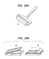
- This embodiment is related to coating using a roller.
- a roller 261 illustrated in FIG. 26A was used to conduct coating.
- the whole surface coating was able to be realized while fixing the whole surface of a recorded product by a screen type presser 262 illustrated in FIG. 26B.
- increase of the initial optical density and great improvement in shelf stability were achieved.
- FIGS. 27A to 27D schematically illustrate a coating operation
- FIGS. 28A and 28B are cross-sectional views of the coating device.
- This embodiment has the constitution that an auxiliary roller 281 forming a conveying means of a recorded product is arranged on a coating roller 282.
- Reference numeral 284 indicates a blade for wiping off an excess liquid, and 286 a guide plate.
- the liquid is poured from a container 272 into the coating device 271, and an ink-jet recorded product 287 is passed through between the rollers 281 and 282 as illustrated in FIGS. 28A and 28B, whereby the liquid is coated.
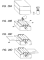
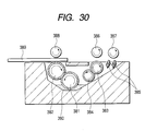
- FIGS. 29A to 29D and 30 illustrate a coating device 291 having a coating roller and a wipe roller, by which sufficient coating is surely performed, and in which the wipe roller has such a mechanism that wiping is more surely performed by an auxiliary roller.
- FIGS. 29A to 29D schematically illustrate the state of the coating
- FIG. 30 is a cross-sectional view illustrating the mechanism of the device. Since the transmission system of driving is not important, the description thereof is omitted.
- the liquid indicated by referential numeral 380 is transferred by rollers 381, 382 and applied to a recorded product 389. An excess liquid is wiped off by a sponge roller 383 and removed by a roller 384. When a blade 385 is additionally provided, the wiping becomes perfect.
- Reference numerals 386, 387 and 388 indicate auxiliary rollers, which form a moving means for the recorded product. In this embodiment, sufficient effects are also achieved in initial properties and shelf stability.
- uniform coating for achieving better shelf performance under exposure to the air than a silver salt photograph can be cheaply practiced directly to images without presence of any optical film, and so techniques for developing a new culture can be provided.
- the invention provides a coating implement for applying a nonvolatile liquid for protection treatment, which does not dissolve a coloring material, to a recorded product which is provided with a porous layer as an ink-receiving layer on the surface of a substrate, and on which an image has been formed with the coloring material adsorbed on at least the porous layer, thereby protecting the image, wherein a coating surface for applying the liquid to the porous layer having the image is supported by a supporting member, and the coating surface can hold the liquid.
Landscapes
- Application Of Or Painting With Fluid Materials (AREA)
- Ink Jet (AREA)
- Printing Methods (AREA)
- Ink Jet Recording Methods And Recording Media Thereof (AREA)
- Manufacturing Of Printed Circuit Boards (AREA)
Applications Claiming Priority (2)
| Application Number | Priority Date | Filing Date | Title |
|---|---|---|---|
| JP2001242722 | 2001-08-09 | ||
| JP2001242722 | 2001-08-09 |
Publications (3)
| Publication Number | Publication Date |
|---|---|
| EP1284201A2 true EP1284201A2 (de) | 2003-02-19 |
| EP1284201A3 EP1284201A3 (de) | 2004-01-21 |
| EP1284201B1 EP1284201B1 (de) | 2008-07-16 |
Family
ID=19072954
Family Applications (1)
| Application Number | Title | Priority Date | Filing Date |
|---|---|---|---|
| EP02017858A Expired - Lifetime EP1284201B1 (de) | 2001-08-09 | 2002-08-08 | Verfahren zum Schutz eines bedruckten Produkts |
Country Status (10)
| Country | Link |
|---|---|
| US (1) | US6833158B2 (de) |
| EP (1) | EP1284201B1 (de) |
| KR (1) | KR100564852B1 (de) |
| CN (1) | CN1236862C (de) |
| AT (1) | ATE401202T1 (de) |
| AU (1) | AU2002300551B2 (de) |
| CA (1) | CA2397474C (de) |
| DE (1) | DE60227618D1 (de) |
| SG (1) | SG111959A1 (de) |
| TW (1) | TW579338B (de) |
Cited By (2)
| Publication number | Priority date | Publication date | Assignee | Title |
|---|---|---|---|---|
| EP1375183A3 (de) * | 2002-06-27 | 2005-01-19 | Canon Kabushiki Kaisha | Vorrichtung zum Übertragen von Flüssigkeiten, Verfahren zum Übertragen von Flüssigkeiten und Verfahren zur Überwachung der Restflüssigkeitsmenge in der Vorrichtung zum Übertragen von Flüssigkeiten |
| CN117772510A (zh) * | 2024-02-23 | 2024-03-29 | 常州市爱伦机械有限公司 | 一种轴承抹油输送系统及其工作方法 |
Families Citing this family (16)
| Publication number | Priority date | Publication date | Assignee | Title |
|---|---|---|---|---|
| US7008671B2 (en) * | 2000-12-28 | 2006-03-07 | Canon Kabushiki Kaisha | Recorded matter, method of producing recorded matter, method for improving image fastness, image fastness-improving agent, image fastness improving kit, dispenser, and applicator |
| JP3925348B2 (ja) * | 2001-08-10 | 2007-06-06 | セイコーエプソン株式会社 | インクジェット記録物及び該記録物の製造に使用する熱転写シート |
| US6857736B2 (en) * | 2001-08-10 | 2005-02-22 | Seiko Epson Corporation | Ink jet recorded matter and production process therefor, and thermal transfer sheet, ink jet recording apparatus, thermal transfer apparatus, and ink jet recording medium |
| US6851880B2 (en) * | 2001-09-04 | 2005-02-08 | Canon Kabushiki Kaisha | Coating tool and coating set |
| US20070032570A1 (en) * | 2003-11-11 | 2007-02-08 | Canon Kabushiki Kaisha | Ink comprising a block copolymer dispersing agent having a hydrophilic and a hydrophobic segment and an ink-applying process and apparatus using the same |
| JPWO2006028285A1 (ja) * | 2004-09-08 | 2008-05-08 | キヤノン株式会社 | 顔料結晶製造段階における中間化学物質、それを用いた顔料結晶製造方法、顔料結晶体 |
| JPWO2006028268A1 (ja) * | 2004-09-08 | 2008-05-08 | キヤノン株式会社 | 顔料、顔料の製造方法、顔料分散体、顔料分散体の製造方法、記録用インク、記録方法及び記録画像 |
| WO2006028267A1 (ja) | 2004-09-08 | 2006-03-16 | Canon Kabushiki Kaisha | 被覆微粒子、分散微粒子、被覆微粒子の製造方法、インク、記録方法及び記録画像 |
| CN1775533B (zh) * | 2004-11-19 | 2011-06-15 | 佳能株式会社 | 喷墨打印方法和喷墨打印装置 |
| US7654662B2 (en) * | 2004-11-19 | 2010-02-02 | Canon Kabushiki Kaisha | Ink jet printing method and ink jet printing apparatus |
| JP4808418B2 (ja) * | 2005-02-28 | 2011-11-02 | キヤノンファインテック株式会社 | インクジェット用水系インク、インクジェット記録方法、インクカートリッジおよびインクジェット記録装置 |
| JP4851167B2 (ja) | 2005-11-07 | 2012-01-11 | キヤノンファインテック株式会社 | インクジェット用水性インク、インクジェット記録方法、インクカートリッジおよびインクジェット記録装置 |
| JP2008018711A (ja) * | 2006-06-14 | 2008-01-31 | Canon Inc | インクジェット記録装置、データ生成装置および記録物 |
| EP3205958B1 (de) | 2010-02-01 | 2019-11-13 | LG Electronics Inc. | Kühlschrank |
| CN111570214B (zh) * | 2020-05-12 | 2025-01-03 | 黄莹松 | 一种皮质拉片封装机中的涂胶机构 |
| CN114855502A (zh) * | 2022-05-11 | 2022-08-05 | 北京山川物语科技有限公司 | 一种用于喷墨数字印刷纸张的水性涂布液及制备方法 |
Citations (6)
| Publication number | Priority date | Publication date | Assignee | Title |
|---|---|---|---|---|
| US4202870A (en) | 1979-04-23 | 1980-05-13 | Union Carbide Corporation | Process for producing alumina |
| US4242271A (en) | 1979-04-23 | 1980-12-30 | Union Carbide Corporation | Process for preparing aluminum alkoxides |
| JPS5744605A (en) | 1980-07-03 | 1982-03-13 | Wacker Chemie Gmbh | Manufacture of halogenated vinyl polymer |
| JPH0948180A (ja) | 1995-08-08 | 1997-02-18 | Taiho Ind Co Ltd | 水性インク印字物保護剤及び保護方法 |
| JP2803134B2 (ja) | 1988-03-16 | 1998-09-24 | 日産化学工業株式会社 | 細長い形状のシリカゾル及びその製造法 |
| JP2881847B2 (ja) | 1988-12-15 | 1999-04-12 | 日産化学工業株式会社 | コーティング用組成物及びその製造法 |
Family Cites Families (12)
| Publication number | Priority date | Publication date | Assignee | Title |
|---|---|---|---|---|
| DE2951242A1 (de) | 1979-12-19 | 1981-07-02 | Alfred 8000 München Aichinger | Vorrichtung zum reinigen und pflegenden benetzen einer flaeche |
| JPS5677154A (en) * | 1979-11-29 | 1981-06-25 | Fuji Photo Film Co Ltd | Ink jet recording method |
| US5808645A (en) | 1992-11-25 | 1998-09-15 | Tektronix, Inc. | Removable applicator assembly for applying a liquid layer |
| JPH07101159A (ja) * | 1993-10-04 | 1995-04-18 | Kimoto & Co Ltd | 感熱式プリンタ用画像形成材料 |
| JPH0966679A (ja) * | 1995-09-01 | 1997-03-11 | Oji Paper Co Ltd | 溶融転写型記録シートおよびその形成方法 |
| JPH0985944A (ja) * | 1995-09-26 | 1997-03-31 | Nitto Denko Corp | 情報シート及びその製造方法並びに印刷装置 |
| US6142618A (en) | 1998-04-29 | 2000-11-07 | Xerox Corporation | System for depositing image enhancing fluid and ink jet printing process employing said system |
| JP2000153677A (ja) * | 1998-11-18 | 2000-06-06 | Dainippon Printing Co Ltd | 印画物形成方法、インクジェット用保護層転写フィルム、印画物、及びインクジェット用プリンター |
| KR100616119B1 (ko) * | 1999-05-18 | 2006-08-25 | 후지 기카이 고교 가부시키가이샤 | 인쇄판체에 대한 도포액 공급장치 |
| WO2001068377A1 (en) | 2000-03-13 | 2001-09-20 | Seiko Epson Corporation | Method for surface treatment, surface-treated article and device for surface treatment |
| KR20020010394A (ko) * | 2000-07-29 | 2002-02-04 | 김병철 | 도장용 전사지의 제조방법 |
| US7008671B2 (en) | 2000-12-28 | 2006-03-07 | Canon Kabushiki Kaisha | Recorded matter, method of producing recorded matter, method for improving image fastness, image fastness-improving agent, image fastness improving kit, dispenser, and applicator |
-
2002
- 2002-08-06 US US10/212,034 patent/US6833158B2/en not_active Expired - Fee Related
- 2002-08-07 SG SG200204796A patent/SG111959A1/en unknown
- 2002-08-08 AU AU2002300551A patent/AU2002300551B2/en not_active Ceased
- 2002-08-08 AT AT02017858T patent/ATE401202T1/de not_active IP Right Cessation
- 2002-08-08 CA CA002397474A patent/CA2397474C/en not_active Expired - Fee Related
- 2002-08-08 DE DE60227618T patent/DE60227618D1/de not_active Expired - Lifetime
- 2002-08-08 EP EP02017858A patent/EP1284201B1/de not_active Expired - Lifetime
- 2002-08-08 TW TW091117904A patent/TW579338B/zh not_active IP Right Cessation
- 2002-08-09 CN CNB021495432A patent/CN1236862C/zh not_active Expired - Fee Related
- 2002-08-09 KR KR1020020046975A patent/KR100564852B1/ko not_active Expired - Fee Related
Patent Citations (6)
| Publication number | Priority date | Publication date | Assignee | Title |
|---|---|---|---|---|
| US4202870A (en) | 1979-04-23 | 1980-05-13 | Union Carbide Corporation | Process for producing alumina |
| US4242271A (en) | 1979-04-23 | 1980-12-30 | Union Carbide Corporation | Process for preparing aluminum alkoxides |
| JPS5744605A (en) | 1980-07-03 | 1982-03-13 | Wacker Chemie Gmbh | Manufacture of halogenated vinyl polymer |
| JP2803134B2 (ja) | 1988-03-16 | 1998-09-24 | 日産化学工業株式会社 | 細長い形状のシリカゾル及びその製造法 |
| JP2881847B2 (ja) | 1988-12-15 | 1999-04-12 | 日産化学工業株式会社 | コーティング用組成物及びその製造法 |
| JPH0948180A (ja) | 1995-08-08 | 1997-02-18 | Taiho Ind Co Ltd | 水性インク印字物保護剤及び保護方法 |
Cited By (3)
| Publication number | Priority date | Publication date | Assignee | Title |
|---|---|---|---|---|
| EP1375183A3 (de) * | 2002-06-27 | 2005-01-19 | Canon Kabushiki Kaisha | Vorrichtung zum Übertragen von Flüssigkeiten, Verfahren zum Übertragen von Flüssigkeiten und Verfahren zur Überwachung der Restflüssigkeitsmenge in der Vorrichtung zum Übertragen von Flüssigkeiten |
| CN117772510A (zh) * | 2024-02-23 | 2024-03-29 | 常州市爱伦机械有限公司 | 一种轴承抹油输送系统及其工作方法 |
| CN117772510B (zh) * | 2024-02-23 | 2024-05-03 | 常州市爱伦机械有限公司 | 一种轴承抹油输送系统及其工作方法 |
Also Published As
| Publication number | Publication date |
|---|---|
| AU2002300551B2 (en) | 2008-01-24 |
| SG111959A1 (en) | 2005-06-29 |
| ATE401202T1 (de) | 2008-08-15 |
| US6833158B2 (en) | 2004-12-21 |
| CN1404926A (zh) | 2003-03-26 |
| KR100564852B1 (ko) | 2006-03-30 |
| DE60227618D1 (de) | 2008-08-28 |
| CN1236862C (zh) | 2006-01-18 |
| CA2397474A1 (en) | 2003-02-09 |
| TW579338B (en) | 2004-03-11 |
| US20030054113A1 (en) | 2003-03-20 |
| EP1284201B1 (de) | 2008-07-16 |
| KR20030014145A (ko) | 2003-02-15 |
| EP1284201A3 (de) | 2004-01-21 |
| CA2397474C (en) | 2006-03-14 |
Similar Documents
| Publication | Publication Date | Title |
|---|---|---|
| CA2397474C (en) | Coating apparatus and coating method of liquid for protection of recorded product, and protection process of recorded product | |
| EP0233039B1 (de) | Bildaufzeichnungsverfahren | |
| JPH0662001B2 (ja) | インクジェット用被記録材 | |
| JPS62261476A (ja) | 被記録材およびそれを用いた記録方法 | |
| EP1221381A2 (de) | Aufgezeichnete Materie, Herstellungsverfahren einer aufgezeichneten Materie, Verfahren zur Verbesserung der Stabilität des Bildes, Mittel zur Verbesserung der Bildestabilität, Kit für die Verbesserung der Bildstabilität, Spender und Applikator | |
| EP0754560B1 (de) | Mehrfarbige Tintenstrahlaufzeichnungsschicht | |
| JP2579038B2 (ja) | 透明基体材料 | |
| HK1052324A (en) | Coating apparatus and coating method of liquid for protection of recorded product, and protection process of recorded product | |
| JPS61230978A (ja) | 被記録材 | |
| JPH0899458A (ja) | インクジェットプリンタ用記録材 | |
| WO1998021048A1 (en) | Water-color ink absorbing material and laminated film having layer of the absorbing material | |
| US6153310A (en) | Ink jet recording sheet | |
| JP2003118223A (ja) | 記録物保護用液体の塗布機器、塗布方法及び記録物保護方法 | |
| JP3977077B2 (ja) | 記録物、記録物の製造方法及び画像堅牢性の向上方法 | |
| JPS61237682A (ja) | 被記録材 | |
| JP4191075B2 (ja) | インクジェット記録シート | |
| JP4492990B2 (ja) | インクジェット記録用シート及びその製造方法 | |
| JP3188596B2 (ja) | 被記録材、その製造方法、インクジェット記録方法及び印字物の製造方法 | |
| JP4397506B2 (ja) | 光沢膜付記録用シート | |
| JPS6135277A (ja) | 被記録材 | |
| JP4208503B2 (ja) | 画像堅牢性向上方法 | |
| JPH08187935A (ja) | インク記録媒体 | |
| JP2004142135A (ja) | インクジェット記録用紙とその製造方法 | |
| JPS62146673A (ja) | 被記録材 | |
| JP2006175327A (ja) | 液体塗布装置及び液体塗布方法 |
Legal Events
| Date | Code | Title | Description |
|---|---|---|---|
| PUAI | Public reference made under article 153(3) epc to a published international application that has entered the european phase |
Free format text: ORIGINAL CODE: 0009012 |
|
| AK | Designated contracting states |
Designated state(s): AT BE BG CH CY CZ DE DK EE ES FI FR GB GR IE IT LI LU MC NL PT SE SK TR |
|
| AX | Request for extension of the european patent |
Extension state: AL LT LV MK RO SI |
|
| PUAL | Search report despatched |
Free format text: ORIGINAL CODE: 0009013 |
|
| AK | Designated contracting states |
Kind code of ref document: A3 Designated state(s): AT BE BG CH CY CZ DE DK EE ES FI FR GB GR IE IT LI LU MC NL PT SE SK TR |
|
| AX | Request for extension of the european patent |
Extension state: AL LT LV MK RO SI |
|
| 17P | Request for examination filed |
Effective date: 20040602 |
|
| AKX | Designation fees paid |
Designated state(s): AT BE BG CH CY CZ DE DK EE ES FI FR GB GR IE IT LI LU MC NL PT SE SK TR |
|
| 17Q | First examination report despatched |
Effective date: 20050830 |
|
| RTI1 | Title (correction) |
Free format text: PROTECTION PROCESS OF RECORDED PRODUCT |
|
| GRAP | Despatch of communication of intention to grant a patent |
Free format text: ORIGINAL CODE: EPIDOSNIGR1 |
|
| GRAS | Grant fee paid |
Free format text: ORIGINAL CODE: EPIDOSNIGR3 |
|
| GRAA | (expected) grant |
Free format text: ORIGINAL CODE: 0009210 |
|
| AK | Designated contracting states |
Kind code of ref document: B1 Designated state(s): AT BE BG CH CY CZ DE DK EE ES FI FR GB GR IE IT LI LU MC NL PT SE SK TR |
|
| REG | Reference to a national code |
Ref country code: GB Ref legal event code: FG4D |
|
| REG | Reference to a national code |
Ref country code: CH Ref legal event code: EP |
|
| REF | Corresponds to: |
Ref document number: 60227618 Country of ref document: DE Date of ref document: 20080828 Kind code of ref document: P |
|
| REG | Reference to a national code |
Ref country code: IE Ref legal event code: FG4D |
|
| NLV1 | Nl: lapsed or annulled due to failure to fulfill the requirements of art. 29p and 29m of the patents act | ||
| PG25 | Lapsed in a contracting state [announced via postgrant information from national office to epo] |
Ref country code: PT Free format text: LAPSE BECAUSE OF FAILURE TO SUBMIT A TRANSLATION OF THE DESCRIPTION OR TO PAY THE FEE WITHIN THE PRESCRIBED TIME-LIMIT Effective date: 20081216 Ref country code: ES Free format text: LAPSE BECAUSE OF FAILURE TO SUBMIT A TRANSLATION OF THE DESCRIPTION OR TO PAY THE FEE WITHIN THE PRESCRIBED TIME-LIMIT Effective date: 20081027 Ref country code: NL Free format text: LAPSE BECAUSE OF FAILURE TO SUBMIT A TRANSLATION OF THE DESCRIPTION OR TO PAY THE FEE WITHIN THE PRESCRIBED TIME-LIMIT Effective date: 20080716 |
|
| PG25 | Lapsed in a contracting state [announced via postgrant information from national office to epo] |
Ref country code: AT Free format text: LAPSE BECAUSE OF FAILURE TO SUBMIT A TRANSLATION OF THE DESCRIPTION OR TO PAY THE FEE WITHIN THE PRESCRIBED TIME-LIMIT Effective date: 20080716 Ref country code: FI Free format text: LAPSE BECAUSE OF FAILURE TO SUBMIT A TRANSLATION OF THE DESCRIPTION OR TO PAY THE FEE WITHIN THE PRESCRIBED TIME-LIMIT Effective date: 20080716 Ref country code: BG Free format text: LAPSE BECAUSE OF FAILURE TO SUBMIT A TRANSLATION OF THE DESCRIPTION OR TO PAY THE FEE WITHIN THE PRESCRIBED TIME-LIMIT Effective date: 20081016 |
|
| PG25 | Lapsed in a contracting state [announced via postgrant information from national office to epo] |
Ref country code: BE Free format text: LAPSE BECAUSE OF FAILURE TO SUBMIT A TRANSLATION OF THE DESCRIPTION OR TO PAY THE FEE WITHIN THE PRESCRIBED TIME-LIMIT Effective date: 20080716 Ref country code: MC Free format text: LAPSE BECAUSE OF NON-PAYMENT OF DUE FEES Effective date: 20080831 |
|
| REG | Reference to a national code |
Ref country code: CH Ref legal event code: PL |
|
| PG25 | Lapsed in a contracting state [announced via postgrant information from national office to epo] |
Ref country code: DK Free format text: LAPSE BECAUSE OF FAILURE TO SUBMIT A TRANSLATION OF THE DESCRIPTION OR TO PAY THE FEE WITHIN THE PRESCRIBED TIME-LIMIT Effective date: 20080716 Ref country code: EE Free format text: LAPSE BECAUSE OF FAILURE TO SUBMIT A TRANSLATION OF THE DESCRIPTION OR TO PAY THE FEE WITHIN THE PRESCRIBED TIME-LIMIT Effective date: 20080716 |
|
| PLBE | No opposition filed within time limit |
Free format text: ORIGINAL CODE: 0009261 |
|
| STAA | Information on the status of an ep patent application or granted ep patent |
Free format text: STATUS: NO OPPOSITION FILED WITHIN TIME LIMIT |
|
| PG25 | Lapsed in a contracting state [announced via postgrant information from national office to epo] |
Ref country code: SK Free format text: LAPSE BECAUSE OF FAILURE TO SUBMIT A TRANSLATION OF THE DESCRIPTION OR TO PAY THE FEE WITHIN THE PRESCRIBED TIME-LIMIT Effective date: 20080716 Ref country code: CZ Free format text: LAPSE BECAUSE OF FAILURE TO SUBMIT A TRANSLATION OF THE DESCRIPTION OR TO PAY THE FEE WITHIN THE PRESCRIBED TIME-LIMIT Effective date: 20080716 |
|
| 26N | No opposition filed |
Effective date: 20090417 |
|
| PG25 | Lapsed in a contracting state [announced via postgrant information from national office to epo] |
Ref country code: LI Free format text: LAPSE BECAUSE OF NON-PAYMENT OF DUE FEES Effective date: 20080831 Ref country code: CH Free format text: LAPSE BECAUSE OF NON-PAYMENT OF DUE FEES Effective date: 20080831 |
|
| PG25 | Lapsed in a contracting state [announced via postgrant information from national office to epo] |
Ref country code: IE Free format text: LAPSE BECAUSE OF NON-PAYMENT OF DUE FEES Effective date: 20080808 |
|
| PG25 | Lapsed in a contracting state [announced via postgrant information from national office to epo] |
Ref country code: IT Free format text: LAPSE BECAUSE OF FAILURE TO SUBMIT A TRANSLATION OF THE DESCRIPTION OR TO PAY THE FEE WITHIN THE PRESCRIBED TIME-LIMIT Effective date: 20080716 |
|
| PG25 | Lapsed in a contracting state [announced via postgrant information from national office to epo] |
Ref country code: SE Free format text: LAPSE BECAUSE OF FAILURE TO SUBMIT A TRANSLATION OF THE DESCRIPTION OR TO PAY THE FEE WITHIN THE PRESCRIBED TIME-LIMIT Effective date: 20081016 |
|
| REG | Reference to a national code |
Ref country code: HK Ref legal event code: WD Ref document number: 1052324 Country of ref document: HK |
|
| PG25 | Lapsed in a contracting state [announced via postgrant information from national office to epo] |
Ref country code: LU Free format text: LAPSE BECAUSE OF NON-PAYMENT OF DUE FEES Effective date: 20080808 Ref country code: CY Free format text: LAPSE BECAUSE OF FAILURE TO SUBMIT A TRANSLATION OF THE DESCRIPTION OR TO PAY THE FEE WITHIN THE PRESCRIBED TIME-LIMIT Effective date: 20080716 |
|
| PG25 | Lapsed in a contracting state [announced via postgrant information from national office to epo] |
Ref country code: TR Free format text: LAPSE BECAUSE OF FAILURE TO SUBMIT A TRANSLATION OF THE DESCRIPTION OR TO PAY THE FEE WITHIN THE PRESCRIBED TIME-LIMIT Effective date: 20080716 |
|
| PG25 | Lapsed in a contracting state [announced via postgrant information from national office to epo] |
Ref country code: GR Free format text: LAPSE BECAUSE OF FAILURE TO SUBMIT A TRANSLATION OF THE DESCRIPTION OR TO PAY THE FEE WITHIN THE PRESCRIBED TIME-LIMIT Effective date: 20081017 |
|
| REG | Reference to a national code |
Ref country code: FR Ref legal event code: PLFP Year of fee payment: 14 |
|
| PGFP | Annual fee paid to national office [announced via postgrant information from national office to epo] |
Ref country code: GB Payment date: 20150826 Year of fee payment: 14 Ref country code: DE Payment date: 20150831 Year of fee payment: 14 |
|
| PGFP | Annual fee paid to national office [announced via postgrant information from national office to epo] |
Ref country code: FR Payment date: 20150826 Year of fee payment: 14 |
|
| REG | Reference to a national code |
Ref country code: DE Ref legal event code: R119 Ref document number: 60227618 Country of ref document: DE |
|
| GBPC | Gb: european patent ceased through non-payment of renewal fee |
Effective date: 20160808 |
|
| REG | Reference to a national code |
Ref country code: FR Ref legal event code: ST Effective date: 20170428 |
|
| PG25 | Lapsed in a contracting state [announced via postgrant information from national office to epo] |
Ref country code: FR Free format text: LAPSE BECAUSE OF NON-PAYMENT OF DUE FEES Effective date: 20160831 Ref country code: DE Free format text: LAPSE BECAUSE OF NON-PAYMENT OF DUE FEES Effective date: 20170301 Ref country code: GB Free format text: LAPSE BECAUSE OF NON-PAYMENT OF DUE FEES Effective date: 20160808 |