EP1284356A2 - Sauganlage für eine Brennkraftmaschine - Google Patents
Sauganlage für eine Brennkraftmaschine Download PDFInfo
- Publication number
- EP1284356A2 EP1284356A2 EP02014199A EP02014199A EP1284356A2 EP 1284356 A2 EP1284356 A2 EP 1284356A2 EP 02014199 A EP02014199 A EP 02014199A EP 02014199 A EP02014199 A EP 02014199A EP 1284356 A2 EP1284356 A2 EP 1284356A2
- Authority
- EP
- European Patent Office
- Prior art keywords
- container
- openings
- suction system
- internal combustion
- combustion engine
- Prior art date
- Legal status (The legal status is an assumption and is not a legal conclusion. Google has not performed a legal analysis and makes no representation as to the accuracy of the status listed.)
- Granted
Links
Images


Classifications
-
- F—MECHANICAL ENGINEERING; LIGHTING; HEATING; WEAPONS; BLASTING
- F02—COMBUSTION ENGINES; HOT-GAS OR COMBUSTION-PRODUCT ENGINE PLANTS
- F02B—INTERNAL-COMBUSTION PISTON ENGINES; COMBUSTION ENGINES IN GENERAL
- F02B75/00—Other engines
- F02B75/16—Engines characterised by number of cylinders, e.g. single-cylinder engines
- F02B75/18—Multi-cylinder engines
- F02B75/24—Multi-cylinder engines with cylinders arranged oppositely relative to main shaft and of "flat" type
- F02B75/243—Multi-cylinder engines with cylinders arranged oppositely relative to main shaft and of "flat" type with only one crankshaft of the "boxer" type, e.g. all connecting rods attached to separate crankshaft bearings
-
- F—MECHANICAL ENGINEERING; LIGHTING; HEATING; WEAPONS; BLASTING
- F02—COMBUSTION ENGINES; HOT-GAS OR COMBUSTION-PRODUCT ENGINE PLANTS
- F02M—SUPPLYING COMBUSTION ENGINES IN GENERAL WITH COMBUSTIBLE MIXTURES OR CONSTITUENTS THEREOF
- F02M35/00—Combustion-air cleaners, air intakes, intake silencers, or induction systems specially adapted for, or arranged on, internal-combustion engines
- F02M35/10—Air intakes; Induction systems
- F02M35/1034—Manufacturing and assembling intake systems
- F02M35/10354—Joining multiple sections together
- F02M35/1036—Joining multiple sections together by welding, bonding or the like
-
- F—MECHANICAL ENGINEERING; LIGHTING; HEATING; WEAPONS; BLASTING
- F02—COMBUSTION ENGINES; HOT-GAS OR COMBUSTION-PRODUCT ENGINE PLANTS
- F02M—SUPPLYING COMBUSTION ENGINES IN GENERAL WITH COMBUSTIBLE MIXTURES OR CONSTITUENTS THEREOF
- F02M35/00—Combustion-air cleaners, air intakes, intake silencers, or induction systems specially adapted for, or arranged on, internal-combustion engines
- F02M35/10—Air intakes; Induction systems
- F02M35/104—Intake manifolds
- F02M35/116—Intake manifolds for engines with cylinders in V-arrangement or arranged oppositely relative to the main shaft
- F02M35/1165—Boxer or pancake engines
-
- F—MECHANICAL ENGINEERING; LIGHTING; HEATING; WEAPONS; BLASTING
- F02—COMBUSTION ENGINES; HOT-GAS OR COMBUSTION-PRODUCT ENGINE PLANTS
- F02M—SUPPLYING COMBUSTION ENGINES IN GENERAL WITH COMBUSTIBLE MIXTURES OR CONSTITUENTS THEREOF
- F02M35/00—Combustion-air cleaners, air intakes, intake silencers, or induction systems specially adapted for, or arranged on, internal-combustion engines
- F02M35/12—Intake silencers ; Sound modulation, transmission or amplification
- F02M35/1205—Flow throttling or guiding
- F02M35/1216—Flow throttling or guiding by using a plurality of holes, slits, protrusions, perforations, ribs or the like; Surface structures; Turbulence generators
-
- F—MECHANICAL ENGINEERING; LIGHTING; HEATING; WEAPONS; BLASTING
- F02—COMBUSTION ENGINES; HOT-GAS OR COMBUSTION-PRODUCT ENGINE PLANTS
- F02M—SUPPLYING COMBUSTION ENGINES IN GENERAL WITH COMBUSTIBLE MIXTURES OR CONSTITUENTS THEREOF
- F02M35/00—Combustion-air cleaners, air intakes, intake silencers, or induction systems specially adapted for, or arranged on, internal-combustion engines
- F02M35/12—Intake silencers ; Sound modulation, transmission or amplification
- F02M35/1255—Intake silencers ; Sound modulation, transmission or amplification using resonance
-
- B—PERFORMING OPERATIONS; TRANSPORTING
- B29—WORKING OF PLASTICS; WORKING OF SUBSTANCES IN A PLASTIC STATE IN GENERAL
- B29C—SHAPING OR JOINING OF PLASTICS; SHAPING OF MATERIAL IN A PLASTIC STATE, NOT OTHERWISE PROVIDED FOR; AFTER-TREATMENT OF THE SHAPED PRODUCTS, e.g. REPAIRING
- B29C65/00—Joining or sealing of preformed parts, e.g. welding of plastics materials; Apparatus therefor
- B29C65/02—Joining or sealing of preformed parts, e.g. welding of plastics materials; Apparatus therefor by heating, with or without pressure
- B29C65/06—Joining or sealing of preformed parts, e.g. welding of plastics materials; Apparatus therefor by heating, with or without pressure using friction, e.g. spin welding
-
- B—PERFORMING OPERATIONS; TRANSPORTING
- B29—WORKING OF PLASTICS; WORKING OF SUBSTANCES IN A PLASTIC STATE IN GENERAL
- B29C—SHAPING OR JOINING OF PLASTICS; SHAPING OF MATERIAL IN A PLASTIC STATE, NOT OTHERWISE PROVIDED FOR; AFTER-TREATMENT OF THE SHAPED PRODUCTS, e.g. REPAIRING
- B29C66/00—General aspects of processes or apparatus for joining preformed parts
- B29C66/01—General aspects dealing with the joint area or with the area to be joined
- B29C66/05—Particular design of joint configurations
- B29C66/10—Particular design of joint configurations particular design of the joint cross-sections
- B29C66/13—Single flanged joints; Fin-type joints; Single hem joints; Edge joints; Interpenetrating fingered joints; Other specific particular designs of joint cross-sections not provided for in groups B29C66/11 - B29C66/12
- B29C66/131—Single flanged joints, i.e. one of the parts to be joined being rigid and flanged in the joint area
- B29C66/1312—Single flange to flange joints, the parts to be joined being rigid
-
- B—PERFORMING OPERATIONS; TRANSPORTING
- B29—WORKING OF PLASTICS; WORKING OF SUBSTANCES IN A PLASTIC STATE IN GENERAL
- B29C—SHAPING OR JOINING OF PLASTICS; SHAPING OF MATERIAL IN A PLASTIC STATE, NOT OTHERWISE PROVIDED FOR; AFTER-TREATMENT OF THE SHAPED PRODUCTS, e.g. REPAIRING
- B29C66/00—General aspects of processes or apparatus for joining preformed parts
- B29C66/01—General aspects dealing with the joint area or with the area to be joined
- B29C66/05—Particular design of joint configurations
- B29C66/301—Three-dimensional joints, i.e. the joined area being substantially non-flat
-
- B—PERFORMING OPERATIONS; TRANSPORTING
- B29—WORKING OF PLASTICS; WORKING OF SUBSTANCES IN A PLASTIC STATE IN GENERAL
- B29C—SHAPING OR JOINING OF PLASTICS; SHAPING OF MATERIAL IN A PLASTIC STATE, NOT OTHERWISE PROVIDED FOR; AFTER-TREATMENT OF THE SHAPED PRODUCTS, e.g. REPAIRING
- B29C66/00—General aspects of processes or apparatus for joining preformed parts
- B29C66/01—General aspects dealing with the joint area or with the area to be joined
- B29C66/32—Measures for keeping the burr form under control; Avoiding burr formation; Shaping the burr
- B29C66/322—Providing cavities in the joined article to collect the burr
-
- B—PERFORMING OPERATIONS; TRANSPORTING
- B29—WORKING OF PLASTICS; WORKING OF SUBSTANCES IN A PLASTIC STATE IN GENERAL
- B29C—SHAPING OR JOINING OF PLASTICS; SHAPING OF MATERIAL IN A PLASTIC STATE, NOT OTHERWISE PROVIDED FOR; AFTER-TREATMENT OF THE SHAPED PRODUCTS, e.g. REPAIRING
- B29C66/00—General aspects of processes or apparatus for joining preformed parts
- B29C66/50—General aspects of joining tubular articles; General aspects of joining long products, i.e. bars or profiled elements; General aspects of joining single elements to tubular articles, hollow articles or bars; General aspects of joining several hollow-preforms to form hollow or tubular articles
- B29C66/51—Joining tubular articles, profiled elements or bars; Joining single elements to tubular articles, hollow articles or bars; Joining several hollow-preforms to form hollow or tubular articles
- B29C66/54—Joining several hollow-preforms, e.g. half-shells, to form hollow articles, e.g. for making balls, containers; Joining several hollow-preforms, e.g. half-cylinders, to form tubular articles
- B29C66/543—Joining several hollow-preforms, e.g. half-shells, to form hollow articles, e.g. for making balls, containers; Joining several hollow-preforms, e.g. half-cylinders, to form tubular articles joining more than two hollow-preforms to form said hollow articles
Definitions
- the invention relates to an intake system for an internal combustion engine according to the preamble of claim 1.
- the reduction of noise emissions more sophisticated Internal combustion engines is a priority development task in which the components such as Suction system, air filter or the like. Of particular importance. Due to the high Gas dynamics within the suction system result in high flow rates. This leads to stalls at various radii and transitions in the suction system, on the basis of which the air volume is excited broadband; a corresponding The result is noise.
- the reflection chamber should be easy to manufacture from a manufacturing point of view and entire running time of the engine reliably on the intake system of the internal combustion engine be attached.
- Both the container and the openings advantageously exist sealing lid made of plastic, preferably by vibration welding are interconnected.
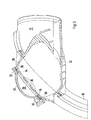
- the suction system 2 designed for a 6 - cylinder boxer engine has for each Cylinder row a resonance tank 4 and 6, both via two connecting pipes 8 and 10 are interconnected; Connection pipe 8 is as a distribution pipe and Connecting tube 10 designed as a resonance tube with a switchable flap. To the Manifold 8 is not in a known manner via a connecting pipe 12 Throttle body shown attached. Of the two resonance tanks 4 and 6 each lead three individual tubes 14 to 16 or 17 to 19 to one each Cylinder head shown on which these individual tubes via corresponding flanges 21st and 23 are attached.
- the resonance container 4 and the one piece thereon connected single pipes 14 to 16 manufactured in a two-shell technique one Upper shell 20 is joined to a lower shell 22 by vibration welding are.
- a resonance chamber 24 is formed in the resonance container 4, via which the Combustion air drawn in via the individual pipes 14 to 16 into the cylinder head and thus passes into the combustion chamber of the individual cylinders.
- the upper shell 20 is a Provided openings 26 wall portion 28 which, as in the following described in more detail, part of a coupled to the resonance chamber 24 Reflection or resonator chamber 29 is.
- the perforated wall section 28 is closed to the outside by a cover 30, the cover 30 by Vibration welding is attached to the resonance tank 4.
- the punched Wall section 28 surrounded by a circumferential web 32, the weld for the two components 20 and 30 made of plastic. So that the Vibration welding plasticizing plastic neither into the inside Reflection chamber 29 can still pass outside, are parallel to the circumferential An inner web (34) and an outer web 36 are provided, which are used for limiting or Serve absorption of the sweat.
- the through the openings 26 to the Resonance chamber 24 connected reflection chamber 29 contributes to a reduction in Noise caused by the high flow velocities of the sucked in Air masses and at different radii and transitions in the suction system occurring stalls occur.
Landscapes
- Engineering & Computer Science (AREA)
- Chemical & Material Sciences (AREA)
- Combustion & Propulsion (AREA)
- Mechanical Engineering (AREA)
- General Engineering & Computer Science (AREA)
- Manufacturing & Machinery (AREA)
- Cylinder Crankcases Of Internal Combustion Engines (AREA)
- Characterised By The Charging Evacuation (AREA)
- Lining Or Joining Of Plastics Or The Like (AREA)
Abstract
Description
- Fig. 1
- eine Explosionsdarstellung einer Sauganlage einer mehrzylindrigen Brennkraftmaschine,
- Fig. 2
- eine Explosionsdarstellung eines Teils der Sauganlage und
- Fig. 3
- eine Schnittdarstellung durch die Sauganlage im Bereich einer Resonatorkammer.
Claims (4)
- Sauganlage für eine Brennkraftmaschine, die mit mindestens einem Behälter versehen ist, der über Zuführungsleitungen mit den Ansaugkanälen eines Zylinderkopfes verbindbar ist, wobei die Öffnungen der Ansaugkanäle zur Gaswechselsteuerung durch Ventile überwacht sind und dass im Behälter oder in den Zuführungsleitungen mindestens eine Reflektionskammer vorgesehen ist, die über eine Lochstruktur mit dem Behältervolumen in Verbindung steht, dadurch gekennzeichnet, dass zur Ausbildung der Reflektionskammer (29) ein Wandungsabschnitt (28) des Behälters (4, 6) Öffnungen (26) aufweist, die durch einen an der Außenseite der Behälterwand (4, 6) befestigten Deckel (30) abgeschlossen sind.
- Sauganlage nach Anspruch 1, dadurch gekennzeichnet, dass der Behälter (4, 6) und der Deckel (30) aus Kunststoff bestehen und beide Bauteile (4, 6, 30) durch Vibrationsschweißen miteinander verbunden sind.
- Sauganlage nach Anspruch 1 oder 2, dadurch gekennzeichnet, dass die im Wandungsabschnitt (28) des Behälters (4, 6) vorgesehen Öffnungen (26) von einem Steg (32) umschlossen sind, der als Schweißnaht für das Vibrationsschweißen vorgesehen ist.
- Sauganlage nach Anspruch 3, dadurch gekennzeichnet, dass parallel zum Steg (32) ein Innen- (34) und eine Außensteg (36) verlaufen, die der Aufnahme bzw. Begrenzung des Schweißaustriebs dienen.
Applications Claiming Priority (2)
| Application Number | Priority Date | Filing Date | Title |
|---|---|---|---|
| DE20113496U DE20113496U1 (de) | 2001-08-14 | 2001-08-14 | Sauganlage für eine Brennkraftmaschine |
| DE20113496U | 2001-08-14 |
Publications (3)
| Publication Number | Publication Date |
|---|---|
| EP1284356A2 true EP1284356A2 (de) | 2003-02-19 |
| EP1284356A3 EP1284356A3 (de) | 2004-03-24 |
| EP1284356B1 EP1284356B1 (de) | 2007-02-21 |
Family
ID=7960535
Family Applications (1)
| Application Number | Title | Priority Date | Filing Date |
|---|---|---|---|
| EP02014199A Expired - Lifetime EP1284356B1 (de) | 2001-08-14 | 2002-06-26 | Sauganlage für eine Brennkraftmaschine |
Country Status (4)
| Country | Link |
|---|---|
| US (1) | US6830024B2 (de) |
| EP (1) | EP1284356B1 (de) |
| JP (1) | JP2003139001A (de) |
| DE (2) | DE20113496U1 (de) |
Cited By (6)
| Publication number | Priority date | Publication date | Assignee | Title |
|---|---|---|---|---|
| EP2009272A3 (de) * | 2007-06-28 | 2009-08-05 | MAHLE Filter Systems Japan Corporation | Saugrohr für Verbrennungsmotoren |
| AT510603A4 (de) * | 2011-01-17 | 2012-05-15 | Avl List Gmbh | Brennkraftmaschine mit zumindest einem durch ein resonatorgehäuse gebildeten resonator |
| US8459225B2 (en) | 2011-08-02 | 2013-06-11 | Mann + Hummel Gmbh | Intake system of internal combustion engine |
| DE102012110729A1 (de) * | 2012-11-09 | 2014-05-15 | Veritas Ag | Kunststoffrohr |
| DE102004029746B4 (de) * | 2004-06-19 | 2014-06-12 | Dr. Ing. H.C. F. Porsche Aktiengesellschaft | Sauganlage für eine Brennkraftmaschine mit mindestens zwei Zylinderbankreihen |
| US11578687B1 (en) | 2022-04-05 | 2023-02-14 | Brunswick Corporation | Marine engine intake manifolds having noise attenuation |
Families Citing this family (20)
| Publication number | Priority date | Publication date | Assignee | Title |
|---|---|---|---|---|
| US7246593B2 (en) * | 2002-08-29 | 2007-07-24 | Siemens Canada Limited | Intake module assembly |
| DE10243881A1 (de) * | 2002-09-21 | 2004-04-01 | Mann + Hummel Gmbh | Schalldämpfer zur Verringerung von Luftgeräuschen und Verfahren zur Herstellung desselben |
| JP4305828B2 (ja) * | 2003-03-31 | 2009-07-29 | スズキ株式会社 | 内燃機関の吸気マニホールド |
| DE102004015339B4 (de) | 2004-03-30 | 2015-06-25 | Dr. Ing. H.C. F. Porsche Aktiengesellschaft | Sauganlage für eine Brennkraftmaschine |
| FR2894644B1 (fr) * | 2005-12-12 | 2009-04-03 | Trelleborg Fluid & Acoustic Solutions Tfas | Dispositif d'attenuation des bruits d'un circuit de circulation d'air, notamment pour moteur a combustion interne |
| KR100758103B1 (ko) * | 2006-03-22 | 2007-09-11 | 대기산업 주식회사 | 차량용 레조네이터 |
| JP4722800B2 (ja) * | 2006-09-20 | 2011-07-13 | 本田技研工業株式会社 | レゾネータを備える多気筒内燃機関 |
| FR2913463B1 (fr) * | 2007-03-09 | 2012-01-06 | Trelleborg Reims | Dispositif d'attenuation des bruits sur un circuit d'admission d'air pour moteur a combustion interne |
| DE102007026826A1 (de) * | 2007-06-06 | 2008-12-11 | Mann + Hummel Gmbh | Ansaugsystem |
| KR100909095B1 (ko) | 2007-07-13 | 2009-07-23 | 대기산업 주식회사 | 차량용 레조네이터 |
| US8201536B2 (en) * | 2008-02-01 | 2012-06-19 | GM Global Technology Operations LLC | Intake system with resonator |
| JP2011094633A (ja) * | 2011-02-14 | 2011-05-12 | Honda Motor Co Ltd | レゾネータを備える多気筒内燃機関 |
| GB2496368B (en) * | 2011-10-12 | 2017-05-31 | Ford Global Tech Llc | An acoustic attenuator for an engine booster |
| JP5357293B2 (ja) * | 2012-03-23 | 2013-12-04 | 株式会社マーレ フィルターシステムズ | 内燃機関のインテークマニホールド |
| US9359981B1 (en) | 2015-05-08 | 2016-06-07 | Brunswick Corporation | Outboard motor with sound enhancement device and method for modifying sounds produced by air intake system of an outboard motor |
| US10180121B1 (en) | 2016-04-05 | 2019-01-15 | Brunswick Corporation | Outboard motor with sound enhancement device and method for modifying sounds produced by air intake system of an outboard motor |
| US9909545B1 (en) | 2016-07-26 | 2018-03-06 | Brunswick Corporation | Outboard motor with sound enhancement device and method for modifying sounds produced by air intake system of an outboard motor |
| US10724410B1 (en) | 2017-11-14 | 2020-07-28 | Brunswick Corporation | Exhaust sound enhancement assembly and method for a marine propulsion device |
| US10968876B2 (en) | 2018-01-16 | 2021-04-06 | Ford Global Technologies, Llc | Engine air intake duct with orifice cap and manufacture thereof |
| CN116670386A (zh) * | 2020-07-14 | 2023-08-29 | 托莱多制模和冲模股份有限公司 | 设有集成宽带调谐器的车辆空气过滤器外壳 |
Citations (1)
| Publication number | Priority date | Publication date | Assignee | Title |
|---|---|---|---|---|
| DE19827410A1 (de) | 1997-06-20 | 1999-01-14 | Mann & Hummel Filter | Ansaugsystem, insbesondere zur Verwendung als Ansaugkanal einer Verbrennungskraftmaschine |
Family Cites Families (6)
| Publication number | Priority date | Publication date | Assignee | Title |
|---|---|---|---|---|
| JPH088305Y2 (ja) * | 1987-09-07 | 1996-03-06 | 小島プレス工業株式会社 | 消音器 |
| US5839405A (en) * | 1997-06-27 | 1998-11-24 | Chrysler Corporation | Single/multi-chamber perforated tube resonator for engine induction system |
| JP3439660B2 (ja) * | 1998-07-09 | 2003-08-25 | 豊田紡織株式会社 | レゾネータ |
| DE19902951A1 (de) * | 1999-01-26 | 2000-07-27 | Mann & Hummel Filter | Ansaugvorrichtung mit einem Leitungsabschnitt zur Dämpfung des Ansauggeräusches |
| DE19924870A1 (de) * | 1999-05-29 | 2000-11-30 | Mann & Hummel Filter | Saugrohr für die Ansaugluft von Brennkraftmaschinen mit Entlastungsstelle für Druckwellen |
| JP2001073893A (ja) * | 1999-09-05 | 2001-03-21 | Honda Motor Co Ltd | 不整地走行車両用シュノーケルダクトの構造 |
-
2001
- 2001-08-14 DE DE20113496U patent/DE20113496U1/de not_active Expired - Lifetime
-
2002
- 2002-06-26 DE DE50209521T patent/DE50209521D1/de not_active Expired - Lifetime
- 2002-06-26 EP EP02014199A patent/EP1284356B1/de not_active Expired - Lifetime
- 2002-08-12 JP JP2002235114A patent/JP2003139001A/ja active Pending
- 2002-08-13 US US10/217,131 patent/US6830024B2/en not_active Expired - Lifetime
Patent Citations (1)
| Publication number | Priority date | Publication date | Assignee | Title |
|---|---|---|---|---|
| DE19827410A1 (de) | 1997-06-20 | 1999-01-14 | Mann & Hummel Filter | Ansaugsystem, insbesondere zur Verwendung als Ansaugkanal einer Verbrennungskraftmaschine |
Cited By (9)
| Publication number | Priority date | Publication date | Assignee | Title |
|---|---|---|---|---|
| DE102004029746B4 (de) * | 2004-06-19 | 2014-06-12 | Dr. Ing. H.C. F. Porsche Aktiengesellschaft | Sauganlage für eine Brennkraftmaschine mit mindestens zwei Zylinderbankreihen |
| EP2009272A3 (de) * | 2007-06-28 | 2009-08-05 | MAHLE Filter Systems Japan Corporation | Saugrohr für Verbrennungsmotoren |
| AT510603A4 (de) * | 2011-01-17 | 2012-05-15 | Avl List Gmbh | Brennkraftmaschine mit zumindest einem durch ein resonatorgehäuse gebildeten resonator |
| AT510603B1 (de) * | 2011-01-17 | 2012-05-15 | Avl List Gmbh | Brennkraftmaschine mit zumindest einem durch ein resonatorgehäuse gebildeten resonator |
| WO2012097945A1 (de) | 2011-01-17 | 2012-07-26 | Avl List Gmbh | Brennkraftmaschine mit zumindest einem durch ein resonatorgehäuse gebildeten resonator |
| US8459225B2 (en) | 2011-08-02 | 2013-06-11 | Mann + Hummel Gmbh | Intake system of internal combustion engine |
| US8851041B2 (en) | 2011-08-02 | 2014-10-07 | Mann + Hummel Gmbh | Intake system of internal combustion engine |
| DE102012110729A1 (de) * | 2012-11-09 | 2014-05-15 | Veritas Ag | Kunststoffrohr |
| US11578687B1 (en) | 2022-04-05 | 2023-02-14 | Brunswick Corporation | Marine engine intake manifolds having noise attenuation |
Also Published As
| Publication number | Publication date |
|---|---|
| US6830024B2 (en) | 2004-12-14 |
| US20030041832A1 (en) | 2003-03-06 |
| JP2003139001A (ja) | 2003-05-14 |
| DE50209521D1 (de) | 2007-04-05 |
| EP1284356A3 (de) | 2004-03-24 |
| EP1284356B1 (de) | 2007-02-21 |
| DE20113496U1 (de) | 2001-10-18 |
Similar Documents
| Publication | Publication Date | Title |
|---|---|---|
| EP1284356A2 (de) | Sauganlage für eine Brennkraftmaschine | |
| DE102007043147B4 (de) | Kontinuierlich variabel abgestimmter Resonator | |
| EP0640177B1 (de) | Ansaugrohr und verfahren zu dessen herstellung | |
| DE69805883T2 (de) | Vorrichtung zum Verhindern von Durchströmgeräuschen bei Drosselklappen | |
| EP0990093B1 (de) | Ansaugsystem, insbesondere zur verwendung als ansaugkanal einer verbrennungskraftmaschine | |
| EP1306829B1 (de) | Vorrichtung zur Übertragung von Brennkraftmaschinengeräuschen | |
| CH641245A5 (de) | Frischgasleitung an einem mehrzylinder-verbrennungsmotor. | |
| DE10036241A1 (de) | Integriertes Luftansaugmodul für Benzinmotoren | |
| DE19504223A1 (de) | Schalldämpfer für den Ansaugkanal einer Brennkraftmaschine | |
| DE10144972C1 (de) | Fluidführung, insbesondere in Form eines Rohluftschlauchs zum Einsaugen von Rohluft in einen Luftfilter eines Kraftfahrzeuges | |
| DE19516358C1 (de) | Pulsationsdämpfer für Kraftstoff im Kraftstoffversorgungssystem einer Brennkraftmaschine | |
| DE102008001390A1 (de) | Schalldämpfer | |
| DE19613467A1 (de) | Ansaugsystem für einen Verbrennungsmotor | |
| DE19546545A1 (de) | Saugrohrmodul | |
| DE29708861U1 (de) | Katalysator-Trägerkörper mit Außensicke | |
| DE19753390A1 (de) | Stapelförmig angeordneter, schneckenförmiger Krümmer | |
| EP1400685B1 (de) | Resonatorluftfilter | |
| DE10144015A1 (de) | Abgasanlage für mehrzylindrige Verbrennungsmotoren | |
| DE3234634C2 (de) | ||
| DE2309571A1 (de) | Auspuff-schalldaempfer fuer zweitaktmotore | |
| EP0771392A1 (de) | Luftansaugvorrichtung mit variabler saugrohrlänge | |
| DE102004029746B4 (de) | Sauganlage für eine Brennkraftmaschine mit mindestens zwei Zylinderbankreihen | |
| DE3633929C2 (de) | Luftansauganlage für einen Boxer- oder V-Motor | |
| DE10002240B4 (de) | Vorrichtung zum Erzeugen eines obertonreichen sportlichen Auspuffgeräusches | |
| EP1400662A1 (de) | Resonatorschalldämpfer |
Legal Events
| Date | Code | Title | Description |
|---|---|---|---|
| PUAI | Public reference made under article 153(3) epc to a published international application that has entered the european phase |
Free format text: ORIGINAL CODE: 0009012 |
|
| AK | Designated contracting states |
Designated state(s): AT BE CH CY DE DK ES FI FR GB GR IE IT LI LU MC NL PT SE TR |
|
| AX | Request for extension of the european patent |
Extension state: AL LT LV MK RO SI |
|
| PUAL | Search report despatched |
Free format text: ORIGINAL CODE: 0009013 |
|
| AK | Designated contracting states |
Kind code of ref document: A3 Designated state(s): AT BE CH CY DE DK ES FI FR GB GR IE IT LI LU MC NL PT SE TR |
|
| AX | Request for extension of the european patent |
Extension state: AL LT LV MK RO SI |
|
| RIC1 | Information provided on ipc code assigned before grant |
Ipc: 7F 02M 35/116 B Ipc: 7F 02M 35/12 A |
|
| 17P | Request for examination filed |
Effective date: 20040924 |
|
| AKX | Designation fees paid |
Designated state(s): DE FR GB IT |
|
| 17Q | First examination report despatched |
Effective date: 20050117 |
|
| GRAP | Despatch of communication of intention to grant a patent |
Free format text: ORIGINAL CODE: EPIDOSNIGR1 |
|
| GRAS | Grant fee paid |
Free format text: ORIGINAL CODE: EPIDOSNIGR3 |
|
| GRAA | (expected) grant |
Free format text: ORIGINAL CODE: 0009210 |
|
| AK | Designated contracting states |
Kind code of ref document: B1 Designated state(s): DE FR GB IT |
|
| REG | Reference to a national code |
Ref country code: GB Ref legal event code: FG4D Free format text: NOT ENGLISH |
|
| REF | Corresponds to: |
Ref document number: 50209521 Country of ref document: DE Date of ref document: 20070405 Kind code of ref document: P |
|
| GBT | Gb: translation of ep patent filed (gb section 77(6)(a)/1977) |
Effective date: 20070515 |
|
| ET | Fr: translation filed | ||
| PLBE | No opposition filed within time limit |
Free format text: ORIGINAL CODE: 0009261 |
|
| STAA | Information on the status of an ep patent application or granted ep patent |
Free format text: STATUS: NO OPPOSITION FILED WITHIN TIME LIMIT |
|
| 26N | No opposition filed |
Effective date: 20071122 |
|
| REG | Reference to a national code |
Ref country code: FR Ref legal event code: TP |
|
| REG | Reference to a national code |
Ref country code: FR Ref legal event code: CD |
|
| REG | Reference to a national code |
Ref country code: FR Ref legal event code: TP |
|
| REG | Reference to a national code |
Ref country code: GB Ref legal event code: 732E Free format text: REGISTERED BETWEEN 20110310 AND 20110316 |
|
| REG | Reference to a national code |
Ref country code: GB Ref legal event code: 732E Free format text: REGISTERED BETWEEN 20110331 AND 20110406 |
|
| PGFP | Annual fee paid to national office [announced via postgrant information from national office to epo] |
Ref country code: FR Payment date: 20110630 Year of fee payment: 10 |
|
| PGFP | Annual fee paid to national office [announced via postgrant information from national office to epo] |
Ref country code: GB Payment date: 20110620 Year of fee payment: 10 |
|
| GBPC | Gb: european patent ceased through non-payment of renewal fee |
Effective date: 20120626 |
|
| REG | Reference to a national code |
Ref country code: FR Ref legal event code: ST Effective date: 20130228 |
|
| PG25 | Lapsed in a contracting state [announced via postgrant information from national office to epo] |
Ref country code: GB Free format text: LAPSE BECAUSE OF NON-PAYMENT OF DUE FEES Effective date: 20120626 Ref country code: FR Free format text: LAPSE BECAUSE OF NON-PAYMENT OF DUE FEES Effective date: 20120702 |
|
| PGFP | Annual fee paid to national office [announced via postgrant information from national office to epo] |
Ref country code: IT Payment date: 20160628 Year of fee payment: 15 |
|
| PG25 | Lapsed in a contracting state [announced via postgrant information from national office to epo] |
Ref country code: IT Free format text: LAPSE BECAUSE OF NON-PAYMENT OF DUE FEES Effective date: 20170626 |
|
| PGFP | Annual fee paid to national office [announced via postgrant information from national office to epo] |
Ref country code: DE Payment date: 20200618 Year of fee payment: 19 |
|
| REG | Reference to a national code |
Ref country code: DE Ref legal event code: R119 Ref document number: 50209521 Country of ref document: DE |
|
| PG25 | Lapsed in a contracting state [announced via postgrant information from national office to epo] |
Ref country code: DE Free format text: LAPSE BECAUSE OF NON-PAYMENT OF DUE FEES Effective date: 20220101 |