EP1284358A2 - Injecteur de combustible pour moteur à combustion interne et son procédé de fabrication - Google Patents
Injecteur de combustible pour moteur à combustion interne et son procédé de fabrication Download PDFInfo
- Publication number
- EP1284358A2 EP1284358A2 EP02017865A EP02017865A EP1284358A2 EP 1284358 A2 EP1284358 A2 EP 1284358A2 EP 02017865 A EP02017865 A EP 02017865A EP 02017865 A EP02017865 A EP 02017865A EP 1284358 A2 EP1284358 A2 EP 1284358A2
- Authority
- EP
- European Patent Office
- Prior art keywords
- seat
- injector
- bush
- plug member
- control chamber
- Prior art date
- Legal status (The legal status is an assumption and is not a legal conclusion. Google has not performed a legal analysis and makes no representation as to the accuracy of the status listed.)
- Granted
Links
- 239000000446 fuel Substances 0.000 title claims description 35
- 238000004519 manufacturing process Methods 0.000 title claims description 8
- 238000002485 combustion reaction Methods 0.000 title claims description 7
- 238000007789 sealing Methods 0.000 claims description 15
- 238000000034 method Methods 0.000 claims description 7
- 238000003754 machining Methods 0.000 claims description 5
- 239000012141 concentrate Substances 0.000 claims description 2
- 239000013536 elastomeric material Substances 0.000 description 3
- IJGRMHOSHXDMSA-UHFFFAOYSA-N Atomic nitrogen Chemical compound N#N IJGRMHOSHXDMSA-UHFFFAOYSA-N 0.000 description 2
- 238000009826 distribution Methods 0.000 description 2
- 239000002184 metal Substances 0.000 description 2
- 238000003860 storage Methods 0.000 description 2
- 238000006243 chemical reaction Methods 0.000 description 1
- 238000001816 cooling Methods 0.000 description 1
- 238000005516 engineering process Methods 0.000 description 1
- 238000010438 heat treatment Methods 0.000 description 1
- 238000002347 injection Methods 0.000 description 1
- 239000007924 injection Substances 0.000 description 1
- 239000007788 liquid Substances 0.000 description 1
- 230000001050 lubricating effect Effects 0.000 description 1
- 229910052757 nitrogen Inorganic materials 0.000 description 1
- 230000000284 resting effect Effects 0.000 description 1
Images


Classifications
-
- F—MECHANICAL ENGINEERING; LIGHTING; HEATING; WEAPONS; BLASTING
- F02—COMBUSTION ENGINES; HOT-GAS OR COMBUSTION-PRODUCT ENGINE PLANTS
- F02M—SUPPLYING COMBUSTION ENGINES IN GENERAL WITH COMBUSTIBLE MIXTURES OR CONSTITUENTS THEREOF
- F02M47/00—Fuel-injection apparatus operated cyclically with fuel-injection valves actuated by fluid pressure
- F02M47/02—Fuel-injection apparatus operated cyclically with fuel-injection valves actuated by fluid pressure of accumulator-injector type, i.e. having fuel pressure of accumulator tending to open, and fuel pressure in other chamber tending to close, injection valves and having means for periodically releasing that closing pressure
- F02M47/027—Electrically actuated valves draining the chamber to release the closing pressure
-
- F—MECHANICAL ENGINEERING; LIGHTING; HEATING; WEAPONS; BLASTING
- F02—COMBUSTION ENGINES; HOT-GAS OR COMBUSTION-PRODUCT ENGINE PLANTS
- F02M—SUPPLYING COMBUSTION ENGINES IN GENERAL WITH COMBUSTIBLE MIXTURES OR CONSTITUENTS THEREOF
- F02M2547/00—Special features for fuel-injection valves actuated by fluid pressure
- F02M2547/003—Valve inserts containing control chamber and valve piston
Definitions
- the present invention relates to an internal combustion engine fuel injector comprising an injector body having a seat for a metering valve in turn having an injector control rod control chamber; and to a method of fabricating the injector.
- the injector metering valve control chamber is supplied with pressurized fuel by an inlet conduit communicating with the delivery side of a high-pressure pump via a high-pressure fuel vessel common to all the injectors, and also has a drain conduit normally closed by a shutter controlled by the armature of an electromagnet.
- the metering valve of the injector is normally defined by a valve body in the form of a sleeve closed at one end by an end wall comprising the drain conduit of the control chamber; the lateral wall of the sleeve guides the control rod controlling opening of the injector nozzle, and comprises the control chamber inlet conduit; and the valve body is housed in a seat in the injector body, and has a flange which is locked hermetically against a shoulder of the injector body by a threaded ring nut.
- Known injectors of this sort have various drawbacks.
- machining inside the valve body is difficult, especially in the region of the end wall which must define the precise volume of the control chamber; the outer surface of the sleeve must form a chamber for distributing fuel from the delivery side of the high-pressure pump to the control chamber inlet conduit, so that one or more high-pressure fuel seals must be provided between the outer surface of the sleeve and the relative seat in the injector body; the presence of the seals complicates assembly of the injector components; and the locking action of the ring nut on the valve body flange is distributed over a relatively extensive area of the flange.
- an internal combustion engine fuel injector comprising an injector body having a seat for a metering valve in turn having a control chamber for controlling a control rod; said control chamber having a pressurized-fuel inlet conduit, and a drain conduit controlled by a corresponding shutter; characterized in that said control chamber is defined by two coaxial parts fixed in said seat; one of said parts guiding said control rod and having one of said conduits; and the other of said parts closing said control chamber and having the other of said conduits.
- a fabrication method characterized by comprising the steps of:
- the metering valve must have a given pair of conduit diameters for each type of engine.
- a wide range of metering valves must therefore be fabricated, each with the given pair of conduit diameters designed for the type of engine to which the injector is fitted.
- the injectors according to the invention therefore have the advantage of enabling the two component parts of the metering valve control chamber to be selected, at assembly, with the required two conduit diameters, thus simplifying part storage during fabrication.
- Number 5 in Figure 1 indicates as a whole an internal combustion engine fuel injector comprising a hollow, tapering injector body 6 having an axis 7 and shown only partly in Figure 1.
- One end of injector body 6, at the bottom in Figure 1 has a nozzle (not shown) with one or more injection orifices normally closed by a pin.
- Injector body 6 also comprises an appendix 8 having a pressurized-fuel supply conduit 9 communicating with a fitting 10 connected to a high-pressure fuel pump via a high-pressure fuel vessel or so-called common rail common to all the injectors on the engine.
- Conduit 9 communicates with the injector nozzle via a conduit 11.
- the pin closing the nozzle is normally kept in the closed position by a cylindrical control rod 12 movable axially along a seat 13 formed in injector body 6 and coaxial with axis 7.
- Control rod 12 is controlled by a metering valve indicated as a whole by 14 and controlled by a normally deenergized electromagnet 15 housed in another seat 16 formed in injector body 6, at the opposite end to the nozzle, and also coaxial with axis 7.
- electromagnet 15 controls an armature 17 which is movable, and secured in any known manner, inside seat 16, and which is pushed by a spring 18 to act on a shutter of valve 14 defined, for example, by a ball 19 associated with a plate 21 having a locating cavity.
- Metering valve 14 is housed in another seat 23 coaxial with axis 7 and between seat 13 of rod 12 and seat 16 of electromagnet 15, and comprises a control chamber 24 having a fuel inlet conduit with a calibrated hole 26, and a fuel drain conduit with another calibrated hole 27.
- Calibrated hole 27 is normally closed by ball 19 of shutter 19, 21, while pressurized fuel is fed continually into control chamber 24 through calibrated hole 26, and pushes rod 12 downwards into the Figure 1 position to keep the nozzle of injector 5 closed.
- control chamber 24 is formed in two coaxial parts 29, 31 fixed inside intermediate seat 23 in injector body 6.
- One of the two parts is defined by a hollow member defined by a cylindrical bush 29, which is fixed inside intermediate seat 23 as shown in detail later on, comprises calibrated hole 26 of the inlet conduit, and has a cylindrical through opening 32 in which is guided a portion 33 of control rod 12.
- the other of the two parts defining control chamber 24 is defined by a plug member 31 having calibrated hole 27 of the drain conduit, and which is also fixed inside intermediate seat 23 of body 6.
- Cylindrical opening 32 of bush 29 must be precision machined to guide portion 33 of rod 12 accurately in its movement, while at the same time sealing in the pressurized fuel; portion 33 comprises two annular grooves 34 for lubricating opening 32 with the same fuel; plug member 31 comprises a bottom surface 35 for arresting an end surface 36 of rod 12 defining the bottom of control chamber 24; and end surface 36 is truncated-cone-shaped so as to leave the outlet of inlet conduit 26 clear even when rod 12 is in the top limit position.
- Bush 29 has a precision machined cylindrical outer surface 37 comprising an annular groove 38 forming a distribution chamber for distributing pressurized fuel from conduit 9 to calibrated hole 26 of the inlet conduit of control chamber 24, and terminates with two annular end edges 39 and 41, which are also precision machined, also as regards squareness with respect to axis 7.
- the diameter of portion 33 of rod 12 may advantageously be at least half the diameter of outer surface 37 of bush 29.
- the diameter of portion 33 of rod 12 may be roughly 4.3 mm, and the diameter of outer surface 37 may be 8 mm or less.
- Intermediate seat 23 of metering valve 14 comprises a top portion 42, a perfectly cylindrical intermediate portion 43, and a bottom portion 44.
- Top portion 42 is threaded for the purpose explained later on;
- cylindrical intermediate portion 43 is precision machined to receive surface 37 of bush 29;
- bottom portion 44 of seat 23 is slightly larger in diameter than intermediate portion 43, and forms an annular shoulder 46 with seat 13.
- Plug member 31 comprises a top surface 47 ( Figure 2) having a truncated-cone-shaped depression 48 coaxial with calibrated hole 27 and for centering the action of ball 19 on hole 27.
- the drain conduit also comprises a larger-diameter prehole 49 forming an additional volume to that of control chamber 24; plug member 31 comprises an annular surface 50 contacting the top edge 41 of bush 29, and which is precision machined to engage edge 41 in pressurized-fueltight manner; and plug member 31 comprises a lateral surface 51 of substantially the same diameter as outer surface 37 of bush 29, and which engages with a minimum amount of clearance the cylindrical surface of a connecting portion 52 between intermediate portion 43 and threaded portion 42 of intermediate seat 23.
- Top surface 47 of plug member 31 comprises an annular portion 53, which is also precision machined and is engaged by a ring nut 54 having an externally threaded lateral wall 56 by which it screws inside threaded portion 42 of intermediate seat 23.
- Ring nut 54 has substantially the same outside diameter as the lateral surface of plug member 31 and outer surface 37 of bush 29, so that its action in fastening plug member 31 is exerted on the thickness of bush 29, with no lever arm being formed with the pressure of the fuel in control chamber 24 or with the reaction of shoulder 46 of portion 44 of intermediate seat 23.
- the thickness of wall 56 of ring nut 54 is preferably about 40% that of bush 29, and, to concentrate the fastening action of ring nut 54 on a small surface area of plug member 31, ring nut 54 has a bottom annular projection 57 of a width equal to about a third of the thickness of wall 56. Moreover, projection 57 is located adjacent to the inner surface of wall 56, so as to act substantially along the centerline of the thickness of bush 29.
- plug member 31 comprises a flange 58 integral with a coaxial cylindrical appendix 59 having flat bottom surface 35 of plug member 31.
- Appendix 59 is housed with a limited amount of clearance inside opening 32 of bush 29, and is of such a length as to leave the outlet of calibrated hole 26 of the inlet conduit clear.
- Flat surface 35, the length of prehole 49, and truncated-cone-shaped end surface 36 of rod 12 therefore define the volume of control chamber 24.
- calibrated hole 27 is preferably formed through the truncated-cone-shaped top surface 48 of plug member 31.
- appendix 59 of plug member 31 comprises an annular groove 60 adjacent to flange 58 to permit precision machining of the lateral surface of appendix 59 and surface 50 of flange 58. Sealing between flange 58 and the surface of top edge 41 is achieved easily over the whole surface of edge 41 by the squareness of edge 41 and surface 50 of flange 58 with respect to axis 7.
- bush 29 is first driven inside cylindrical portion 43 of intermediate seat 23 - e.g. by first heating body 6 and cooling bush 29 with liquid nitrogen - so that edge 39 of bush 29 rests on shoulder 46 of portion 44 of seat 23.
- Appendix 59 of plug member 31 is then inserted inside opening 32 of bush 29.
- ring nut 54 is screwed inside threaded portion 42 of seat 23 to so fasten surface 50 of plug member 31 against top edge 41 of bush 29 as to ensure sealing of the pressurized fuel in chamber 24.
- top edge 41 of bush 29 has an annular recess 61 housing a seal 62 of elastomeric material.
- Seal 62 provides for sealing between flange 58 and edge 41 of bush 29 over a smaller diameter than in Figures 1 and 2, so that less fastening pressure is required of ring nut 54, and groove 60 in Figure 2 may also be dispensed with, since such sealing may even be achieved in the presence of minor roughness of the portion of metal surface 50 adjacent to appendix 59.
- assembly of metering valve 14 in Figure 3 also comprises inserting seal 62 inside annular recess 61.
- plug member 31 is defined by a straightforward disk 63 engaged by projection 57 of ring nut 54 for fluidtight assembly to edge 41 of bush 29.
- an end portion 64 of portion 33 of rod 12 is smaller in diameter to form a gap 66 with through opening 32 of bush 29.
- the volume of gap 66 is added to that of control chamber 24 to compensate for the reduction in volume caused by the reduction in the length of prehole 49. Since disk 63 has a shorter prehole 49 than in the Figure 1-3 embodiments, calibrated hole 27 in disk 63 may be formed working through prehole 49, so that the two are more easily made coaxial.
- bush 29 comprises annular recess 61 housing seal 62 of elastomeric material to reduce the diameter of the sealing area and ensure sealing even in the presence of minor roughness of the two contacting metal surfaces.
- the method of fabricating injector 5 comprises the steps of:
- the method comprises the steps of:
- control chamber 24 in two parts 29, 31 simplifies machining of the inside of chamber 24; driving bush 29 into cylindrical portion 43 of seat 23 provides for direct sealing of the pressurized fuel in distribution chamber 38; whereas the slight interference between bush 29 and cylindrical portion 43 prevents any deformation of the two parts during assembly, and makes subsequent grinding superfluous.
- the fastening force of ring nut 54 is exerted over the thickness of bush 29; projection 57 of ring nut 54 provides for concentrating the fastening force over a smaller diameter, thus ensuring optimum fastening; and forming the two calibrated holes 26, 27 in two separate parts 29, 31 enables parts 29, 31 to be selected when assembling injector 5, thus simplifying part storage.
- bush 29 may be other than circular in section; top surface 47 of plug member 31 may be flat as opposed to truncated-cone-shaped; and the inlet conduit of control chamber 24 and the drain conduit may be parallel and perpendicular to rod 12 respectively.
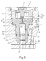
- FIG. 6 shows a further embodiment of the present invention, in which any parts similar or corresponding to those of the other embodiments are indicated using the same reference numbers.
- Figure 6 injector differs from those in Figures 1-5 by bush 29 being fixed conventionally to injector body 6 as opposed to interferentially.
- bush 29 is inserted radially loosely inside injector body 6, and two sealing rings 72, 73 of elastomeric material are provided on opposite axial sides of annular groove 38, between injector body 6 and bush 29, to prevent the high-pressure fuel fed into annular groove 38 along feed conduit 9 from leaking into the gap between injector body 6 and bush 29.
- seat 23 housing bush 29 comprises a wider top chamber 74 defined axially by an annular shoulder 75 of injector body 6, and which houses plug member 31 and ring nut 54; and bush 29 has a substantially T-shaped section, and comprises a wide top end portion 76 resting on annular shoulder 75.
Landscapes
- Engineering & Computer Science (AREA)
- Physics & Mathematics (AREA)
- Fluid Mechanics (AREA)
- Chemical & Material Sciences (AREA)
- Combustion & Propulsion (AREA)
- Mechanical Engineering (AREA)
- General Engineering & Computer Science (AREA)
- Fuel-Injection Apparatus (AREA)
Applications Claiming Priority (2)
| Application Number | Priority Date | Filing Date | Title |
|---|---|---|---|
| ITTO20010814 | 2001-08-14 | ||
| IT2001TO000814A ITTO20010814A1 (it) | 2001-08-14 | 2001-08-14 | Iniettore di combustibile per un motore endotermico e relativo metododi fabbricazione. |
Publications (3)
| Publication Number | Publication Date |
|---|---|
| EP1284358A2 true EP1284358A2 (fr) | 2003-02-19 |
| EP1284358A3 EP1284358A3 (fr) | 2003-11-19 |
| EP1284358B1 EP1284358B1 (fr) | 2007-07-04 |
Family
ID=11459151
Family Applications (1)
| Application Number | Title | Priority Date | Filing Date |
|---|---|---|---|
| EP02017865A Expired - Lifetime EP1284358B1 (fr) | 2001-08-14 | 2002-08-08 | Injecteur de combustible pour moteur à combustion interne et son procédé de fabrication |
Country Status (5)
| Country | Link |
|---|---|
| US (1) | US6905083B2 (fr) |
| EP (1) | EP1284358B1 (fr) |
| AT (1) | ATE366358T1 (fr) |
| DE (1) | DE60220974T2 (fr) |
| IT (1) | ITTO20010814A1 (fr) |
Cited By (3)
| Publication number | Priority date | Publication date | Assignee | Title |
|---|---|---|---|---|
| EP1657435B1 (fr) * | 2004-11-12 | 2007-02-28 | C.R.F. Società Consortile per Azioni | Injecteur de combustible pour moteur à combustion interne |
| EP2808532A1 (fr) * | 2013-05-30 | 2014-12-03 | Delphi International Operations Luxembourg S.à r.l. | Injecteur de carburant |
| DE102019212262A1 (de) * | 2019-08-15 | 2021-02-18 | Elringklinger Ag | Dichtungsanordnung, Hochdruckpumpe und Verfahren zur Herstellung einer Dichtungsanordnung |
Families Citing this family (10)
| Publication number | Priority date | Publication date | Assignee | Title |
|---|---|---|---|---|
| DE10122245A1 (de) * | 2001-05-08 | 2002-12-12 | Bosch Gmbh Robert | Leckagereduzierter druckgesteuerter Kraftstoffinjektor |
| EP1612403B1 (fr) * | 2004-06-30 | 2007-01-10 | C.R.F. Società Consortile per Azioni | Soupape servo pour controller l'injecteur d'un moteur à combustion interne |
| AT501668B1 (de) * | 2004-08-24 | 2007-03-15 | Bosch Gmbh Robert | Steuerventil für eine einspritzdüse |
| DE102005004069A1 (de) * | 2005-01-28 | 2006-08-03 | Volkswagen Mechatronic Gmbh & Co. Kg | Einspritzvorrichtung mit einer Dichtungsanordnung |
| DE102006003040A1 (de) * | 2006-01-23 | 2007-07-26 | Robert Bosch Gmbh | Kraftstoffinjektor |
| DE102007038139A1 (de) * | 2007-08-13 | 2009-02-19 | Robert Bosch Gmbh | Elektrischer Stecker mit Kraftstoffrücklauf |
| DE102009027727A1 (de) * | 2009-07-15 | 2011-01-20 | Robert Bosch Gmbh | Ventilanordnung |
| HUE026321T2 (en) | 2012-01-26 | 2016-05-30 | Delphi Int Operations Luxembourg Sarl | Fuel Injector Control Valve |
| DE102019220061A1 (de) * | 2019-12-18 | 2021-06-24 | Robert Bosch Gmbh | Kraftstoffinjektor zur Einspritzung von Kraftstoff |
| CN113154448B (zh) * | 2021-04-30 | 2022-07-19 | 西安航天动力研究所 | 用于冲压发动机超声速燃烧室燃油喷注与火焰稳定的装置 |
Family Cites Families (12)
| Publication number | Priority date | Publication date | Assignee | Title |
|---|---|---|---|---|
| CH495504A (de) * | 1968-08-28 | 1970-08-31 | Sopromi Soc Proc Modern Inject | Brennstoff-Einspritzventil mit elektromagnetischer Betätigung |
| IT1232027B (it) * | 1989-03-03 | 1992-01-23 | Weber Srl | Perfezionamento ai dispositivi di iniezione del combustibile ad azio namento elettromagnetico per motori a ciclo diesel |
| IT1240173B (it) * | 1990-04-06 | 1993-11-27 | Weber Srl | Dispositivo di iniezione del carburante ad azionamento elettromagnetico per un motore a combustione interna |
| IT1261156B (it) * | 1993-12-30 | 1996-05-09 | Elasis Sistema Ricerca Fiat | Elettromagnete di comando di una valvola di dosaggio per un iniettore di combustibile |
| US5636615A (en) * | 1995-02-21 | 1997-06-10 | Diesel Technology Company | Fuel pumping and injection systems |
| US6027037A (en) * | 1995-12-05 | 2000-02-22 | Denso Corporation | Accumulator fuel injection apparatus for internal combustion engine |
| US5779149A (en) * | 1996-07-02 | 1998-07-14 | Siemens Automotive Corporation | Piezoelectric controlled common rail injector with hydraulic amplification of piezoelectric stroke |
| US5826561A (en) * | 1996-12-10 | 1998-10-27 | Caterpillar Inc. | Method and apparatus for injecting fuel using control fluid to control the injection's pressure and time |
| IT1295462B1 (it) * | 1997-10-02 | 1999-05-12 | Elasis Sistema Ricerca Fiat | Iniettore di combustibile a comando elettromagnetico per motori a combustione interna. |
| IT1296143B1 (it) * | 1997-11-18 | 1999-06-09 | Elasis Sistema Ricerca Fiat | Dispositivo di comando di un iniettore di combustibile per motori a combustione interna. |
| DE19849933C2 (de) * | 1998-10-29 | 2000-09-28 | Siemens Ag | Stellanordnung, insbesondere zur mechanischen Ansteuerung eines Einspritzventils einer Brennkraftmaschine |
| US6293254B1 (en) * | 2000-01-07 | 2001-09-25 | Cummins Engine Company, Inc. | Fuel injector with floating sleeve control chamber |
-
2001
- 2001-08-14 IT IT2001TO000814A patent/ITTO20010814A1/it unknown
-
2002
- 2002-08-08 AT AT02017865T patent/ATE366358T1/de not_active IP Right Cessation
- 2002-08-08 EP EP02017865A patent/EP1284358B1/fr not_active Expired - Lifetime
- 2002-08-08 DE DE60220974T patent/DE60220974T2/de not_active Expired - Lifetime
- 2002-08-14 US US10/218,363 patent/US6905083B2/en not_active Expired - Fee Related
Cited By (4)
| Publication number | Priority date | Publication date | Assignee | Title |
|---|---|---|---|---|
| EP1657435B1 (fr) * | 2004-11-12 | 2007-02-28 | C.R.F. Società Consortile per Azioni | Injecteur de combustible pour moteur à combustion interne |
| EP2808532A1 (fr) * | 2013-05-30 | 2014-12-03 | Delphi International Operations Luxembourg S.à r.l. | Injecteur de carburant |
| DE102019212262A1 (de) * | 2019-08-15 | 2021-02-18 | Elringklinger Ag | Dichtungsanordnung, Hochdruckpumpe und Verfahren zur Herstellung einer Dichtungsanordnung |
| WO2021028580A1 (fr) | 2019-08-15 | 2021-02-18 | Elringklinger Ag | Ensemble d'étanchéité, pompe haute pression et procédé de fabrication d'un ensemble d'étanchéité |
Also Published As
| Publication number | Publication date |
|---|---|
| DE60220974D1 (de) | 2007-08-16 |
| ITTO20010814A0 (it) | 2001-08-14 |
| DE60220974T2 (de) | 2008-03-06 |
| ITTO20010814A1 (it) | 2003-02-14 |
| EP1284358A3 (fr) | 2003-11-19 |
| US20030051700A1 (en) | 2003-03-20 |
| ATE366358T1 (de) | 2007-07-15 |
| US6905083B2 (en) | 2005-06-14 |
| EP1284358B1 (fr) | 2007-07-04 |
Similar Documents
| Publication | Publication Date | Title |
|---|---|---|
| JP4247506B2 (ja) | 内燃機関用燃料噴射装置に用いる調整可能な絞り弁 | |
| US6905083B2 (en) | Internal combustion engine fuel injector and relative fabrication method | |
| US6918409B1 (en) | Spool and poppet inlet metering valve | |
| EP0690223B1 (fr) | Injecteur à combustible et procédé d'ajustement de la levée d'aiguille d'un injecteur à combustible | |
| EP1707798B1 (fr) | Soupape de dosage asservie réglable pour un injecteur de carburant ainsi que sa méthode de réglage | |
| US5067658A (en) | Diesel engine electromagnetic fuel injector | |
| JP4559441B2 (ja) | 燃料噴射装置用サーボ絞り弁 | |
| US5984264A (en) | Perfected electromagnetic metering valve with a ball shutter for a fuel injector | |
| CN101490403A (zh) | 具有压力平衡的控制阀的燃料喷射器 | |
| US6126094A (en) | Internal combustion engine fuel injector | |
| CN101523043B (zh) | 具有一个节流板及一个电磁阀的燃料喷射器 | |
| WO2021255986A1 (fr) | Procédé de réglage de pré-course pour soupape d'injection de combustible | |
| EP1302655B1 (fr) | Dispositif pour la connexion étanche d'un raccord à un injecteur de combustible pour un moteur à combustion interne | |
| EP0976923A2 (fr) | Appareil d'injection de carburant | |
| US12241441B2 (en) | Fuel injector for injecting fuel | |
| JP5760427B2 (ja) | 燃料噴射装置 | |
| EP2218901B1 (fr) | Procédé pour la fabrication d'un élément d'ouverture/fermeture pour servovalves d'un injecteur de carburant | |
| GB2370608A (en) | A control valve for a fuel injector of an internal combustion engine | |
| JPH0932682A (ja) | 内燃機関の燃料噴射装置 |
Legal Events
| Date | Code | Title | Description |
|---|---|---|---|
| PUAI | Public reference made under article 153(3) epc to a published international application that has entered the european phase |
Free format text: ORIGINAL CODE: 0009012 |
|
| AK | Designated contracting states |
Designated state(s): AT BE BG CH CY CZ DE DK EE ES FI FR GB GR IE IT LI LU MC NL PT SE SK TR |
|
| AX | Request for extension of the european patent |
Extension state: AL LT LV MK RO SI |
|
| PUAL | Search report despatched |
Free format text: ORIGINAL CODE: 0009013 |
|
| AK | Designated contracting states |
Kind code of ref document: A3 Designated state(s): AT BE BG CH CY CZ DE DK EE ES FI FR GB GR IE IT LI LU MC NL PT SE SK TR |
|
| AX | Request for extension of the european patent |
Extension state: AL LT LV MK RO SI |
|
| 17P | Request for examination filed |
Effective date: 20040518 |
|
| AKX | Designation fees paid |
Designated state(s): AT BE BG CH CY CZ DE DK EE ES FI FR GB GR IE IT LI LU MC NL PT SE SK TR |
|
| 17Q | First examination report despatched |
Effective date: 20060825 |
|
| GRAP | Despatch of communication of intention to grant a patent |
Free format text: ORIGINAL CODE: EPIDOSNIGR1 |
|
| GRAS | Grant fee paid |
Free format text: ORIGINAL CODE: EPIDOSNIGR3 |
|
| GRAA | (expected) grant |
Free format text: ORIGINAL CODE: 0009210 |
|
| AK | Designated contracting states |
Kind code of ref document: B1 Designated state(s): AT BE BG CH CY CZ DE DK EE ES FI FR GB GR IE IT LI LU MC NL PT SE SK TR |
|
| REG | Reference to a national code |
Ref country code: GB Ref legal event code: FG4D |
|
| REG | Reference to a national code |
Ref country code: CH Ref legal event code: EP |
|
| REG | Reference to a national code |
Ref country code: IE Ref legal event code: FG4D |
|
| REF | Corresponds to: |
Ref document number: 60220974 Country of ref document: DE Date of ref document: 20070816 Kind code of ref document: P |
|
| ET | Fr: translation filed | ||
| NLV1 | Nl: lapsed or annulled due to failure to fulfill the requirements of art. 29p and 29m of the patents act | ||
| REG | Reference to a national code |
Ref country code: CH Ref legal event code: PL |
|
| PG25 | Lapsed in a contracting state [announced via postgrant information from national office to epo] |
Ref country code: NL Free format text: LAPSE BECAUSE OF FAILURE TO SUBMIT A TRANSLATION OF THE DESCRIPTION OR TO PAY THE FEE WITHIN THE PRESCRIBED TIME-LIMIT Effective date: 20070704 Ref country code: FI Free format text: LAPSE BECAUSE OF FAILURE TO SUBMIT A TRANSLATION OF THE DESCRIPTION OR TO PAY THE FEE WITHIN THE PRESCRIBED TIME-LIMIT Effective date: 20070704 Ref country code: BG Free format text: LAPSE BECAUSE OF FAILURE TO SUBMIT A TRANSLATION OF THE DESCRIPTION OR TO PAY THE FEE WITHIN THE PRESCRIBED TIME-LIMIT Effective date: 20071004 Ref country code: ES Free format text: LAPSE BECAUSE OF FAILURE TO SUBMIT A TRANSLATION OF THE DESCRIPTION OR TO PAY THE FEE WITHIN THE PRESCRIBED TIME-LIMIT Effective date: 20071015 Ref country code: PT Free format text: LAPSE BECAUSE OF FAILURE TO SUBMIT A TRANSLATION OF THE DESCRIPTION OR TO PAY THE FEE WITHIN THE PRESCRIBED TIME-LIMIT Effective date: 20071204 |
|
| PG25 | Lapsed in a contracting state [announced via postgrant information from national office to epo] |
Ref country code: LI Free format text: LAPSE BECAUSE OF FAILURE TO SUBMIT A TRANSLATION OF THE DESCRIPTION OR TO PAY THE FEE WITHIN THE PRESCRIBED TIME-LIMIT Effective date: 20070704 Ref country code: CH Free format text: LAPSE BECAUSE OF FAILURE TO SUBMIT A TRANSLATION OF THE DESCRIPTION OR TO PAY THE FEE WITHIN THE PRESCRIBED TIME-LIMIT Effective date: 20070704 Ref country code: AT Free format text: LAPSE BECAUSE OF FAILURE TO SUBMIT A TRANSLATION OF THE DESCRIPTION OR TO PAY THE FEE WITHIN THE PRESCRIBED TIME-LIMIT Effective date: 20070704 |
|
| PG25 | Lapsed in a contracting state [announced via postgrant information from national office to epo] |
Ref country code: BE Free format text: LAPSE BECAUSE OF FAILURE TO SUBMIT A TRANSLATION OF THE DESCRIPTION OR TO PAY THE FEE WITHIN THE PRESCRIBED TIME-LIMIT Effective date: 20070704 |
|
| PG25 | Lapsed in a contracting state [announced via postgrant information from national office to epo] |
Ref country code: MC Free format text: LAPSE BECAUSE OF NON-PAYMENT OF DUE FEES Effective date: 20070831 Ref country code: DK Free format text: LAPSE BECAUSE OF FAILURE TO SUBMIT A TRANSLATION OF THE DESCRIPTION OR TO PAY THE FEE WITHIN THE PRESCRIBED TIME-LIMIT Effective date: 20070704 Ref country code: GR Free format text: LAPSE BECAUSE OF FAILURE TO SUBMIT A TRANSLATION OF THE DESCRIPTION OR TO PAY THE FEE WITHIN THE PRESCRIBED TIME-LIMIT Effective date: 20071005 |
|
| PLBE | No opposition filed within time limit |
Free format text: ORIGINAL CODE: 0009261 |
|
| STAA | Information on the status of an ep patent application or granted ep patent |
Free format text: STATUS: NO OPPOSITION FILED WITHIN TIME LIMIT |
|
| PG25 | Lapsed in a contracting state [announced via postgrant information from national office to epo] |
Ref country code: SK Free format text: LAPSE BECAUSE OF FAILURE TO SUBMIT A TRANSLATION OF THE DESCRIPTION OR TO PAY THE FEE WITHIN THE PRESCRIBED TIME-LIMIT Effective date: 20070704 Ref country code: CZ Free format text: LAPSE BECAUSE OF FAILURE TO SUBMIT A TRANSLATION OF THE DESCRIPTION OR TO PAY THE FEE WITHIN THE PRESCRIBED TIME-LIMIT Effective date: 20070704 |
|
| 26N | No opposition filed |
Effective date: 20080407 |
|
| GBPC | Gb: european patent ceased through non-payment of renewal fee |
Effective date: 20071004 |
|
| PG25 | Lapsed in a contracting state [announced via postgrant information from national office to epo] |
Ref country code: SE Free format text: LAPSE BECAUSE OF FAILURE TO SUBMIT A TRANSLATION OF THE DESCRIPTION OR TO PAY THE FEE WITHIN THE PRESCRIBED TIME-LIMIT Effective date: 20071004 |
|
| PG25 | Lapsed in a contracting state [announced via postgrant information from national office to epo] |
Ref country code: IE Free format text: LAPSE BECAUSE OF NON-PAYMENT OF DUE FEES Effective date: 20070808 |
|
| PG25 | Lapsed in a contracting state [announced via postgrant information from national office to epo] |
Ref country code: GB Free format text: LAPSE BECAUSE OF NON-PAYMENT OF DUE FEES Effective date: 20071004 |
|
| PG25 | Lapsed in a contracting state [announced via postgrant information from national office to epo] |
Ref country code: EE Free format text: LAPSE BECAUSE OF FAILURE TO SUBMIT A TRANSLATION OF THE DESCRIPTION OR TO PAY THE FEE WITHIN THE PRESCRIBED TIME-LIMIT Effective date: 20070704 |
|
| PG25 | Lapsed in a contracting state [announced via postgrant information from national office to epo] |
Ref country code: CY Free format text: LAPSE BECAUSE OF FAILURE TO SUBMIT A TRANSLATION OF THE DESCRIPTION OR TO PAY THE FEE WITHIN THE PRESCRIBED TIME-LIMIT Effective date: 20070704 |
|
| PG25 | Lapsed in a contracting state [announced via postgrant information from national office to epo] |
Ref country code: LU Free format text: LAPSE BECAUSE OF NON-PAYMENT OF DUE FEES Effective date: 20070808 |
|
| PG25 | Lapsed in a contracting state [announced via postgrant information from national office to epo] |
Ref country code: IT Free format text: LAPSE BECAUSE OF NON-PAYMENT OF DUE FEES Effective date: 20070808 Ref country code: TR Free format text: LAPSE BECAUSE OF FAILURE TO SUBMIT A TRANSLATION OF THE DESCRIPTION OR TO PAY THE FEE WITHIN THE PRESCRIBED TIME-LIMIT Effective date: 20070704 |
|
| PGRI | Patent reinstated in contracting state [announced from national office to epo] |
Ref country code: IT Effective date: 20110616 |
|
| REG | Reference to a national code |
Ref country code: FR Ref legal event code: PLFP Year of fee payment: 14 |
|
| PGFP | Annual fee paid to national office [announced via postgrant information from national office to epo] |
Ref country code: DE Payment date: 20150804 Year of fee payment: 14 |
|
| PGFP | Annual fee paid to national office [announced via postgrant information from national office to epo] |
Ref country code: FR Payment date: 20150709 Year of fee payment: 14 |
|
| PGFP | Annual fee paid to national office [announced via postgrant information from national office to epo] |
Ref country code: IT Payment date: 20150804 Year of fee payment: 14 |
|
| REG | Reference to a national code |
Ref country code: DE Ref legal event code: R119 Ref document number: 60220974 Country of ref document: DE |
|
| REG | Reference to a national code |
Ref country code: FR Ref legal event code: ST Effective date: 20170428 |
|
| PG25 | Lapsed in a contracting state [announced via postgrant information from national office to epo] |
Ref country code: FR Free format text: LAPSE BECAUSE OF NON-PAYMENT OF DUE FEES Effective date: 20160831 Ref country code: DE Free format text: LAPSE BECAUSE OF NON-PAYMENT OF DUE FEES Effective date: 20170301 |
|
| PG25 | Lapsed in a contracting state [announced via postgrant information from national office to epo] |
Ref country code: IT Free format text: LAPSE BECAUSE OF NON-PAYMENT OF DUE FEES Effective date: 20160808 |