EP1284368B1 - Deviateur pour réduire l'usure dans une pompe pour matière épaisse - Google Patents
Deviateur pour réduire l'usure dans une pompe pour matière épaisse Download PDFInfo
- Publication number
- EP1284368B1 EP1284368B1 EP02017681A EP02017681A EP1284368B1 EP 1284368 B1 EP1284368 B1 EP 1284368B1 EP 02017681 A EP02017681 A EP 02017681A EP 02017681 A EP02017681 A EP 02017681A EP 1284368 B1 EP1284368 B1 EP 1284368B1
- Authority
- EP
- European Patent Office
- Prior art keywords
- impeller
- diverter
- particles
- front shroud
- suction liner
- Prior art date
- Legal status (The legal status is an assumption and is not a legal conclusion. Google has not performed a legal analysis and makes no representation as to the accuracy of the status listed.)
- Expired - Lifetime
Links
- 239000002002 slurry Substances 0.000 title claims abstract description 17
- 238000011144 upstream manufacturing Methods 0.000 claims description 3
- 239000013618 particulate matter Substances 0.000 claims description 2
- 239000002245 particle Substances 0.000 abstract description 39
- 239000007788 liquid Substances 0.000 description 7
- 238000007789 sealing Methods 0.000 description 6
- 238000000034 method Methods 0.000 description 3
- 238000005086 pumping Methods 0.000 description 3
- 239000007787 solid Substances 0.000 description 3
- XLYOFNOQVPJJNP-UHFFFAOYSA-N water Substances O XLYOFNOQVPJJNP-UHFFFAOYSA-N 0.000 description 2
- 239000000470 constituent Substances 0.000 description 1
- 230000000694 effects Effects 0.000 description 1
- 230000005484 gravity Effects 0.000 description 1
- 230000003116 impacting effect Effects 0.000 description 1
- 239000000463 material Substances 0.000 description 1
- 239000002609 medium Substances 0.000 description 1
- 239000000203 mixture Substances 0.000 description 1
- 230000003134 recirculating effect Effects 0.000 description 1
- 239000006163 transport media Substances 0.000 description 1
Images


Classifications
-
- F—MECHANICAL ENGINEERING; LIGHTING; HEATING; WEAPONS; BLASTING
- F04—POSITIVE - DISPLACEMENT MACHINES FOR LIQUIDS; PUMPS FOR LIQUIDS OR ELASTIC FLUIDS
- F04D—NON-POSITIVE-DISPLACEMENT PUMPS
- F04D29/00—Details, component parts, or accessories
- F04D29/18—Rotors
- F04D29/22—Rotors specially for centrifugal pumps
- F04D29/2261—Rotors specially for centrifugal pumps with special measures
- F04D29/2294—Rotors specially for centrifugal pumps with special measures for protection, e.g. against abrasion
-
- F—MECHANICAL ENGINEERING; LIGHTING; HEATING; WEAPONS; BLASTING
- F04—POSITIVE - DISPLACEMENT MACHINES FOR LIQUIDS; PUMPS FOR LIQUIDS OR ELASTIC FLUIDS
- F04D—NON-POSITIVE-DISPLACEMENT PUMPS
- F04D29/00—Details, component parts, or accessories
- F04D29/08—Sealings
- F04D29/16—Sealings between pressure and suction sides
- F04D29/165—Sealings between pressure and suction sides especially adapted for liquid pumps
- F04D29/167—Sealings between pressure and suction sides especially adapted for liquid pumps of a centrifugal flow wheel
-
- F—MECHANICAL ENGINEERING; LIGHTING; HEATING; WEAPONS; BLASTING
- F04—POSITIVE - DISPLACEMENT MACHINES FOR LIQUIDS; PUMPS FOR LIQUIDS OR ELASTIC FLUIDS
- F04D—NON-POSITIVE-DISPLACEMENT PUMPS
- F04D29/00—Details, component parts, or accessories
- F04D29/40—Casings; Connections of working fluid
- F04D29/42—Casings; Connections of working fluid for radial or helico-centrifugal pumps
- F04D29/426—Casings; Connections of working fluid for radial or helico-centrifugal pumps especially adapted for liquid pumps
- F04D29/4273—Casings; Connections of working fluid for radial or helico-centrifugal pumps especially adapted for liquid pumps suction eyes
Definitions
- the present invention generally relates to a slurry pump for use in pumping a slurry and in particular to a diverter for directing particles away from a stationary face and impeller nose gap to reduce wear.
- a slurry pump comprises an impeller consisting of a connecting hub and shrouds with a number of vanes rotating in a volute collector or casing. Liquid is led into the center of the impeller and is picked up by the vanes and accelerated to a high velocity by the rotation of the impeller and discharged by centrifugal force into the casing and out the discharge. When liquid is forced away from the center, a vacuum is created and more liquid flows in. Consequently there is a flow through the pump.
- Centrifugal pumps may be configured as single stage, single suction pumps having an impeller connected to a shaft and sandwiched between a front and back shroud.
- the rotation of the impeller vanes results in a higher pressure in the volute collector or shell than in the suction, which results in a flow.
- the higher pressure zone of the volute collector is sealed against the low pressure zone of the suction where the shah (at a lower atmospheric pressure) enters the collector to avoid leakage losses and loss of performance.
- the most common method of sealing is to use a close radial clearance between the impeller and the casing.
- the solids/liquid mixture moved through the slurry pump induces great wear and shortens the pump's life. Wear occurs mostly as a result of particles impacting on the wetted surfaces. The amount of wear depends on the particle size, shape, specific gravity of the solids hardness and sharpness most of which is dictated by the service and the velocity of the impacts and the number (or concentration) of impacts. The wear varies with about the 2.5 power of the velocity.
- the front clearing vanes develop a pressure similar to the impeller vanes.
- the clearing vanes pump the leakage flow from the collector to the suction, thereby reducing wear in the nose gap area.
- US-A-3 881 840 discloses a centrifugal pump for processing liquids containing abrasive constituents comprising a housing with a suction opening and a delivery opening and an impeller and having on either side sealing faces located at least partially on the outer side of a sealing slot in which slot, near the entrance side, an annular chamber is formed and means are provided for rotating the liquid in the chamber and near the outer circumference radial, outwardly directed ducts communicate with the annular chamber and open out by a diameter which is smaller than the diameter of the impeller.
- US-A-3 620 642 discloses another centrifugal slurry pump comprising intake chamber means, casing means defining volute means therein, a follower plate means disposed between said intake chamber means and said casing means, impeller means rotatably supported within said casing means and having pumping impeller vanes thereon.
- the impeller means including pressure relief means adjacent said follower plate means for reducing secondary circulation between the follower plate and impeller means, and means on said follower plate means and extending toward said impeller means to reduce wear occasioned by secondary circulation within the pump.
- a turbo-machine for transporting media loaded with solid particles includes a housing.
- At least one impeller is disposed inside the housing and defines impeller side spaces disposed between the impeller and the housing.
- Wall surfaces bound the impeller side spaces.
- the wall surfaces have various shaped protrusions, recesses, blades and grooves for conducting the flow of the medium near the wall at least partly into regions where the transport medium has a greater rotational motion.
- the present invention includes a diverter for reducing particulate wear in a slurry pump having a suction liner, an impeller with a front shroud, and a nose gap between the suction liner and the front shroud of the impeller.
- the diverter further comprises a suction liner face having a protrusion formed upstream of the nose gap, the protrusion extending inwardly toward the front shroud of the impeller and terminating in a substantially rounded tip; the impeller front shroud being operatively opposed to the suction liner face, a rounded relief formed within the front shroud; and the rounded tip of the protrusion extending into the rounded relief of the front shroud, wherein particulate matter is deflected away from the suction liner face.
- the protrusion is placed upstream of the impeller nose gap such that the number of particles that pass through the nose gap is reduced.
- the impeller front shroud may comprise clearing vanes that can include a relief.
- the protrusion can extend and fit within the relief to farther aid in directing the particles to the clearing vanes.
- the gap formed between the protrusion and the impeller front facing ranges from about 0.5 mm to about 2.5 mm.
- the protrusion can include an outer edge and an inner edge.
- the outer edge is substantially rounded and the inner edge slopes at an angle of about 45 degrees.
- the present invention includes a diverter 2 for directing particles away from the stationary face or suction liner 4 of a slurry pump 20 and away from the impeller nose gap 12. By diverting particles away from the nose gap 12, wear is reduced.
- the diverter 2 comprises a protrusion that extends out from the suction liner 4 and directs particles back into the collector 22 of the pump to reduce the number of particles that pass through the impeller nose gap 12.
- the diverter 2 extends out a distance nearly equal to the distance between the suction liner 4 and the impeller front shroud 10 such that the clearance between the diverter 2 and impeller front shroud 10 is kept at a minimum.
- the diverter 2 directs the slurry and particles that cause wear away from the stationary face of the suction liner 4 to a location where the suction of the clearing vanes 8 can catch the particles and by a centrifugal force, pump them back into the collector 22.
- the wear on the nose gap 12 is greatly reduced since a large portion of the particles that would normally pass through the gap 12 are pumped back into the collector 22.
- the clearing vanes 8 may be stopped off short of the nose of the impeller to provide a relief at the inside.
- the diverter 2 can be positioned to fit within the relief 18 to urge the particles towards the inlet of the clearing vanes 8 and away from the stationary face of the suction liner 4. By urging the particles into the suction area of the front clearing vanes 8, the particles can be pumped back into the volute collector 16. The heavier particles tend to be caught up in the clearing vanes 8 as they are brought close enough. Depending on how close the particles are brought, the size of the clearing vanes 8 and the size of the particles are significantly reduced and a number of particles will find their way through the gap into the suction thereby reducing wear in the high wear nose 12 face area.
- the clearance between the clearing vanes 8 and the suction liner 4 is about 2 mm for a pump with an impeller 18 of 1 meter.
- Smaller diameter impeller pumps can achieve tighter clearances of about 1 mm in the case of .5-meter diameter impeller.
- Impellers 18 with diameters larger than 1 meter have proportionally larger front clearances.
- the impeller front shroud 10 thickness can be a function of the severity of the wear service and the size of the parts.
- a 0.5-meter diameter impeller would have about a 33 mm thick front shroud 10, and a 1-meter diameter impeller would be around 42 mm.
- the front clearing vane 8 depth is generally between 50% to 100% of the front shroud thickness.
- the particles are diverted as closely as possible to the inside of the clearing vanes 8.
- the clearing vanes 8 are relieved or stopped off at their inside diameter to form a recess or relief 18.
- the stationary or circular diverter can take up this relief as closely as possible allowing a practical running clearance of about 2.5 mm for 0.5-meter diameter impeller and 0.5 mm for smaller impellers.
- the shape of the diverter 2 on its outer diameter may be radial or near radial, while on the inside it may be set at about a 45 degree angle to minimize the wear effect of particles being thrown off the impeller.
- the diverter 2 nose may extend out as close as practical to the impeller front shroud 10.
- the clearance under the diverter 2 and between the rotating impeller surface may be kept somewhat larger at around 25% to about 100% of the shroud thickness.
- a protruding piece 2 extends out from the suction liner face 4 near and/or under the inside of the clearing vanes on a slurry pump impeller to divert particles to the impeller front clearing vanes which will cause particles to be pumped back into the main volute collector 22 reducing the concentration, size and/or number of particles that go through the lower sealing nose gap 12 thereby reducing wear in this high nose gap wear area.
- a protrusion 2 on the suction liner will divert abrasive particles away from the liner and improve wear.
- FIG. 1 an embodiment of a centrifugal pump 20 is illustrated showing the discharge nozzle, inlet, impeller and the flow of the slurry in the pump as indicated by the arrows.
- Figure 2 is a further embodiment of a centrifugal pump illustrating the impeller vanes 18 connected to a shaft by which the impeller vanes are turned within the collector or shell that houses the vanes.
- the vanes have an impeller shroud front and an impeller shroud back.
- the front side of the pump is labeled as the suction end of the centrifugal pump.
- the impeller nose gap 12 is located at the meeting of the impeller and collector.
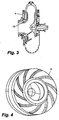
- Figure.3 further depicts a centrifugal pump 14 in greater detail such that a water flush inlet along with the impeller nose gap 12 is illustrated. Further illustrated is a suction liner 4 without the diverter 2 extending from the suction liner. Also shown is the connection shaft, section inlet and outlet. Figure 4 illustrates the clearing vanes 8 protruding from the impeller front shroud 10 for clearing the particles from the suction liner 4 and the impeller nose gap. Figure 5 depicts the impeller nose gap 12 and suction liner 4 without a diverter. Further illustrated is the movement of the particles by the arrows as some of the particles pass up through the clearing vanes and the remaining particles passing through the impeller nose gap 12.
- Figures 6 and 7 illustrate the diverter 2.
- the suction liner 4 having the diverter protrusion 2 extending from the liner and out to a recess in the clearing vanes 8 attached to the impeller front shroud 10 is illustrated.
- Figure 7 illustrates the suction liner 4 and diverter 2.
- the diverter 2 or protrusion comprises an outer edge which is illustrated as substantially rounded 16 and an inner edge 14 set at an angle of about 45°.
Landscapes
- Engineering & Computer Science (AREA)
- Mechanical Engineering (AREA)
- General Engineering & Computer Science (AREA)
- Structures Of Non-Positive Displacement Pumps (AREA)
- Reciprocating Pumps (AREA)
- Details Of Reciprocating Pumps (AREA)
Claims (3)
- Déviateur pour réduire l'usure par particules dans une pompe pour matière, épaisse (20) possédant un chemisage d'aspiration (4), une hélice avec un carénage avant (10) et un interstice de nez (12) entre le chemisage d'aspiration (4) et le carénage avant (10) de l'hélice,
caractérisé en ce que
le déviateur(a) comprend une face de chemisage d'aspiration présentant une protubérance (2) formée en amont de l'interstice de nez (12), la protubérance (2) s'étendant vers l'intérieur en direction du carénage avant (10) de l'hélice et se terminant en un bout pour l'essentiel arrondi ;(b) le carénage avant d'hélice (10) est opposé de façon opérationnelle à la face du chemisage d'aspiration, un relief arrondi étant formé dans le carénage avant (10) ; et(c) le bout arrondi de la protubérance (2) s'étend dans le relief arrondi du carénage avant (10), de la matière en particules étant déviée de la face du chemisage d'aspiration. - Déviateur selon la revendication 1, dans lequel le carénage avant d'hélice (10) comprend des aubes de dégagement (8), le relief arrondi étant formé dans les aubes de dégagement (8).
- Déviateur selon la revendication 1, dans lequel la protubérance (2) comprend une arête intérieure (14), l'arête intérieure (14) s'étendant vers le bas du bout arrondi vers la face du chemisage d'aspiration selon un angle d'environ 45 degrés par rapport à l'horizontal.
Applications Claiming Priority (2)
| Application Number | Priority Date | Filing Date | Title |
|---|---|---|---|
| US31088301P | 2001-08-08 | 2001-08-08 | |
| US310883P | 2001-08-08 |
Publications (3)
| Publication Number | Publication Date |
|---|---|
| EP1284368A2 EP1284368A2 (fr) | 2003-02-19 |
| EP1284368A3 EP1284368A3 (fr) | 2003-12-03 |
| EP1284368B1 true EP1284368B1 (fr) | 2006-03-15 |
Family
ID=23204498
Family Applications (1)
| Application Number | Title | Priority Date | Filing Date |
|---|---|---|---|
| EP02017681A Expired - Lifetime EP1284368B1 (fr) | 2001-08-08 | 2002-08-07 | Deviateur pour réduire l'usure dans une pompe pour matière épaisse |
Country Status (4)
| Country | Link |
|---|---|
| US (1) | US7465153B2 (fr) |
| EP (1) | EP1284368B1 (fr) |
| AT (1) | ATE320562T1 (fr) |
| DE (1) | DE60209837D1 (fr) |
Cited By (1)
| Publication number | Priority date | Publication date | Assignee | Title |
|---|---|---|---|---|
| US7766605B2 (en) | 2003-10-20 | 2010-08-03 | Itt Manufacturing Enterprises Inc. | Centrifugal pump |
Families Citing this family (27)
| Publication number | Priority date | Publication date | Assignee | Title |
|---|---|---|---|---|
| US20040136825A1 (en) * | 2001-08-08 | 2004-07-15 | Addie Graeme R. | Multiple diverter for reducing wear in a slurry pump |
| ATE409279T1 (de) * | 2006-07-14 | 2008-10-15 | Openhydro Group Ltd | Turbinen mit einer rutsche zum durchfluss von fremdkörpern |
| EP1878913B1 (fr) * | 2006-07-14 | 2013-03-13 | OpenHydro Group Limited | Turbine maremotrice bidirectionnelle |
| EP1879280B1 (fr) * | 2006-07-14 | 2014-03-05 | OpenHydro Group Limited | Turbine hydroélectrique |
| EP1878912B1 (fr) * | 2006-07-14 | 2011-12-21 | OpenHydro Group Limited | Turbines hydroélectriques submergées ayant des chambres de flotabilité |
| DE602007001582D1 (de) * | 2007-04-11 | 2009-08-27 | Openhydro Group Ltd | Verfahren zum Einsetzen einer hydroelektrischen Turbine |
| EP1980746B2 (fr) * | 2007-04-11 | 2013-08-07 | OpenHydro Group Limited | Procédé d'installation d'une turbine hydroélectrique |
| ATE480035T1 (de) * | 2007-12-12 | 2010-09-15 | Openhydro Group Ltd | Generatorkomponente für eine hydroelektrische turbine |
| EP2088311B1 (fr) * | 2008-02-05 | 2015-10-14 | OpenHydro Group Limited | Turbine hydroélectrique avec rotor flottant |
| EP2110910A1 (fr) * | 2008-04-17 | 2009-10-21 | OpenHydro Group Limited | Procédé amélioré d'installation de turbine |
| EP2112370B1 (fr) * | 2008-04-22 | 2016-08-31 | OpenHydro Group Limited | Turbine hydroélectrique disposant d'un palier magnétique |
| EP2199599A1 (fr) * | 2008-12-18 | 2010-06-23 | OpenHydro IP Limited | Turbine hydroélectrique avec une expulsion des débris |
| EP2199598B1 (fr) | 2008-12-18 | 2012-05-02 | OpenHydro IP Limited | Turbine hydroélectrique avec un frein passif et procédé d'opération |
| DE602008002602D1 (de) | 2008-12-19 | 2010-10-28 | Openhydro Ip Ltd | Verfahren zum Installieren eines hydroelektrischen Turbinengenerators |
| ATE548562T1 (de) | 2009-04-17 | 2012-03-15 | Openhydro Ip Ltd | Verbessertes verfahren zur steuerung der ausgabe eines hydroelektrischen turbinengenerators |
| EP2302204A1 (fr) | 2009-09-29 | 2011-03-30 | OpenHydro IP Limited | Système de turbine hydroélectrique |
| EP2302766B1 (fr) | 2009-09-29 | 2013-03-13 | OpenHydro IP Limited | Turbine hydroélectrique avec refroidissement de bobine |
| EP2302755B1 (fr) | 2009-09-29 | 2012-11-28 | OpenHydro IP Limited | Système et procédé de conversion d'alimentation électrique |
| DK177190B1 (en) * | 2010-05-03 | 2012-05-21 | Alfa Laval Corp Ab | Centrifugal pumpe |
| EP2450562B1 (fr) | 2010-11-09 | 2015-06-24 | Openhydro IP Limited | Système de récupération pour une turbine hydroélectrique et procédé de récupération |
| EP2469257B1 (fr) | 2010-12-23 | 2014-02-26 | Openhydro IP Limited | Procédé de test de turbine hydroélectrique |
| KR101826819B1 (ko) * | 2017-06-08 | 2018-02-07 | 이재웅 | 원심 슬러리 펌프 및 임펠러 |
| CN109751248B (zh) * | 2018-12-12 | 2021-02-19 | 江苏大学镇江流体工程装备技术研究院 | 一种汽车电子水泵 |
| EP4056851A1 (fr) * | 2021-03-09 | 2022-09-14 | Metso Outotec Sweden AB | Élément d'usure pour une pompe à boue |
| US11713768B1 (en) | 2022-06-22 | 2023-08-01 | Robert Bosch Gmbh | Impeller for a centrifugal pump |
| US12281557B1 (en) | 2024-04-11 | 2025-04-22 | Halliburton Energy Services, Inc. | Multi-well blending system |
| US12385377B1 (en) | 2024-04-11 | 2025-08-12 | Halliburton Energy Services, Inc. | System to optimize centrifugal pumps and manifolding in variable rate slurry pumping applications |
Family Cites Families (3)
| Publication number | Priority date | Publication date | Assignee | Title |
|---|---|---|---|---|
| US3620642A (en) * | 1969-12-09 | 1971-11-16 | Wilfley & Sons Inc A | Centrifugal pump |
| US3881840A (en) | 1973-09-05 | 1975-05-06 | Neratoom | Centrifugal pump for processing liquids containing abrasive constituents, more particularly, a sand pump or a waste-water pumper |
| CN1054418C (zh) | 1993-09-25 | 2000-07-12 | Ksb股份公司 | 磨损小的涡轮机 |
-
2002
- 2002-08-06 US US10/212,919 patent/US7465153B2/en not_active Expired - Lifetime
- 2002-08-07 DE DE60209837T patent/DE60209837D1/de not_active Expired - Lifetime
- 2002-08-07 AT AT02017681T patent/ATE320562T1/de not_active IP Right Cessation
- 2002-08-07 EP EP02017681A patent/EP1284368B1/fr not_active Expired - Lifetime
Cited By (1)
| Publication number | Priority date | Publication date | Assignee | Title |
|---|---|---|---|---|
| US7766605B2 (en) | 2003-10-20 | 2010-08-03 | Itt Manufacturing Enterprises Inc. | Centrifugal pump |
Also Published As
| Publication number | Publication date |
|---|---|
| US7465153B2 (en) | 2008-12-16 |
| ATE320562T1 (de) | 2006-04-15 |
| US20030044272A1 (en) | 2003-03-06 |
| DE60209837D1 (de) | 2006-05-11 |
| EP1284368A3 (fr) | 2003-12-03 |
| EP1284368A2 (fr) | 2003-02-19 |
Similar Documents
| Publication | Publication Date | Title |
|---|---|---|
| EP1284368B1 (fr) | Deviateur pour réduire l'usure dans une pompe pour matière épaisse | |
| US20040136825A1 (en) | Multiple diverter for reducing wear in a slurry pump | |
| EP1633983B2 (fr) | Turbine de pompe amelioree | |
| EP1692397B1 (fr) | Pompe centrifuge | |
| CN109257934B (zh) | 用于泥浆泵的旋转部件 | |
| US5102297A (en) | Centrifugal pump with cavitation reducing propeller | |
| CN118601941A (zh) | 浆料泵的入口部件 | |
| US12510081B2 (en) | Pump casing and pump | |
| CA2839472C (fr) | Ameliorations apportees des pompes et composants utilises a cet effet | |
| US6752597B2 (en) | Duplex shear force rotor | |
| US20220120288A1 (en) | Inverted Annular Side Gap Arrangement For A Centrifugal Pump | |
| EP3874169B1 (fr) | Pompe à courants de foucault | |
| KR102132233B1 (ko) | 고비중 미세슬러리용 원심펌프의 오픈형 임펠러 | |
| WO2018000032A1 (fr) | Pompe à bouillie et ses composants | |
| US7189054B2 (en) | Self-compensating clearance seal for centrifugal pumps | |
| AU2023347066B2 (en) | Froth pump assembly and parts thereof |
Legal Events
| Date | Code | Title | Description |
|---|---|---|---|
| PUAI | Public reference made under article 153(3) epc to a published international application that has entered the european phase |
Free format text: ORIGINAL CODE: 0009012 |
|
| AK | Designated contracting states |
Designated state(s): AT BE BG CH CY CZ DE DK EE ES FI FR GB GR IE IT LI LU MC NL PT SE SK TR |
|
| AX | Request for extension of the european patent |
Extension state: AL LT LV MK RO SI |
|
| RIN1 | Information on inventor provided before grant (corrected) |
Inventor name: MAFFETT, JOHN Inventor name: BROSS, STEPHAN Inventor name: MUELLER, THOMAS Inventor name: ADDIE, GRAEME R. |
|
| PUAL | Search report despatched |
Free format text: ORIGINAL CODE: 0009013 |
|
| AK | Designated contracting states |
Kind code of ref document: A3 Designated state(s): AT BE BG CH CY CZ DE DK EE ES FI FR GB GR IE IT LI LU MC NL PT SE SK TR |
|
| AX | Request for extension of the european patent |
Extension state: AL LT LV MK RO SI |
|
| 17P | Request for examination filed |
Effective date: 20040526 |
|
| AKX | Designation fees paid |
Designated state(s): AT BE BG CH CY CZ DE DK EE ES FI FR GB GR IE IT LI LU MC NL PT SE SK TR |
|
| 17Q | First examination report despatched |
Effective date: 20040729 |
|
| GRAP | Despatch of communication of intention to grant a patent |
Free format text: ORIGINAL CODE: EPIDOSNIGR1 |
|
| GRAS | Grant fee paid |
Free format text: ORIGINAL CODE: EPIDOSNIGR3 |
|
| GRAA | (expected) grant |
Free format text: ORIGINAL CODE: 0009210 |
|
| AK | Designated contracting states |
Kind code of ref document: B1 Designated state(s): AT BE BG CH CY CZ DE DK EE ES FI FR GB GR IE IT LI LU MC NL PT SE SK TR |
|
| PG25 | Lapsed in a contracting state [announced via postgrant information from national office to epo] |
Ref country code: SK Free format text: LAPSE BECAUSE OF FAILURE TO SUBMIT A TRANSLATION OF THE DESCRIPTION OR TO PAY THE FEE WITHIN THE PRESCRIBED TIME-LIMIT Effective date: 20060315 Ref country code: LI Free format text: LAPSE BECAUSE OF FAILURE TO SUBMIT A TRANSLATION OF THE DESCRIPTION OR TO PAY THE FEE WITHIN THE PRESCRIBED TIME-LIMIT Effective date: 20060315 Ref country code: IT Free format text: LAPSE BECAUSE OF FAILURE TO SUBMIT A TRANSLATION OF THE DESCRIPTION OR TO PAY THE FEE WITHIN THE PRESCRIBED TIME-LIMIT;WARNING: LAPSES OF ITALIAN PATENTS WITH EFFECTIVE DATE BEFORE 2007 MAY HAVE OCCURRED AT ANY TIME BEFORE 2007. THE CORRECT EFFECTIVE DATE MAY BE DIFFERENT FROM THE ONE RECORDED. Effective date: 20060315 Ref country code: FI Free format text: LAPSE BECAUSE OF FAILURE TO SUBMIT A TRANSLATION OF THE DESCRIPTION OR TO PAY THE FEE WITHIN THE PRESCRIBED TIME-LIMIT Effective date: 20060315 Ref country code: CH Free format text: LAPSE BECAUSE OF FAILURE TO SUBMIT A TRANSLATION OF THE DESCRIPTION OR TO PAY THE FEE WITHIN THE PRESCRIBED TIME-LIMIT Effective date: 20060315 Ref country code: AT Free format text: LAPSE BECAUSE OF FAILURE TO SUBMIT A TRANSLATION OF THE DESCRIPTION OR TO PAY THE FEE WITHIN THE PRESCRIBED TIME-LIMIT Effective date: 20060315 |
|
| REG | Reference to a national code |
Ref country code: GB Ref legal event code: FG4D Ref country code: CH Ref legal event code: EP |
|
| REG | Reference to a national code |
Ref country code: IE Ref legal event code: FG4D |
|
| REF | Corresponds to: |
Ref document number: 60209837 Country of ref document: DE Date of ref document: 20060511 Kind code of ref document: P |
|
| PG25 | Lapsed in a contracting state [announced via postgrant information from national office to epo] |
Ref country code: SE Free format text: LAPSE BECAUSE OF FAILURE TO SUBMIT A TRANSLATION OF THE DESCRIPTION OR TO PAY THE FEE WITHIN THE PRESCRIBED TIME-LIMIT Effective date: 20060615 Ref country code: DK Free format text: LAPSE BECAUSE OF FAILURE TO SUBMIT A TRANSLATION OF THE DESCRIPTION OR TO PAY THE FEE WITHIN THE PRESCRIBED TIME-LIMIT Effective date: 20060615 Ref country code: BG Free format text: LAPSE BECAUSE OF FAILURE TO SUBMIT A TRANSLATION OF THE DESCRIPTION OR TO PAY THE FEE WITHIN THE PRESCRIBED TIME-LIMIT Effective date: 20060615 |
|
| PG25 | Lapsed in a contracting state [announced via postgrant information from national office to epo] |
Ref country code: DE Free format text: LAPSE BECAUSE OF FAILURE TO SUBMIT A TRANSLATION OF THE DESCRIPTION OR TO PAY THE FEE WITHIN THE PRESCRIBED TIME-LIMIT Effective date: 20060617 |
|
| PG25 | Lapsed in a contracting state [announced via postgrant information from national office to epo] |
Ref country code: ES Free format text: LAPSE BECAUSE OF FAILURE TO SUBMIT A TRANSLATION OF THE DESCRIPTION OR TO PAY THE FEE WITHIN THE PRESCRIBED TIME-LIMIT Effective date: 20060626 |
|
| PG25 | Lapsed in a contracting state [announced via postgrant information from national office to epo] |
Ref country code: IE Free format text: LAPSE BECAUSE OF NON-PAYMENT OF DUE FEES Effective date: 20060808 |
|
| PG25 | Lapsed in a contracting state [announced via postgrant information from national office to epo] |
Ref country code: PT Free format text: LAPSE BECAUSE OF FAILURE TO SUBMIT A TRANSLATION OF THE DESCRIPTION OR TO PAY THE FEE WITHIN THE PRESCRIBED TIME-LIMIT Effective date: 20060816 |
|
| PG25 | Lapsed in a contracting state [announced via postgrant information from national office to epo] |
Ref country code: MC Free format text: LAPSE BECAUSE OF NON-PAYMENT OF DUE FEES Effective date: 20060831 |
|
| REG | Reference to a national code |
Ref country code: CH Ref legal event code: PL |
|
| PLBE | No opposition filed within time limit |
Free format text: ORIGINAL CODE: 0009261 |
|
| STAA | Information on the status of an ep patent application or granted ep patent |
Free format text: STATUS: NO OPPOSITION FILED WITHIN TIME LIMIT |
|
| 26N | No opposition filed |
Effective date: 20061218 |
|
| GBPC | Gb: european patent ceased through non-payment of renewal fee |
Effective date: 20060807 |
|
| EN | Fr: translation not filed | ||
| PG25 | Lapsed in a contracting state [announced via postgrant information from national office to epo] |
Ref country code: GB Free format text: LAPSE BECAUSE OF NON-PAYMENT OF DUE FEES Effective date: 20060807 |
|
| PG25 | Lapsed in a contracting state [announced via postgrant information from national office to epo] |
Ref country code: GR Free format text: LAPSE BECAUSE OF FAILURE TO SUBMIT A TRANSLATION OF THE DESCRIPTION OR TO PAY THE FEE WITHIN THE PRESCRIBED TIME-LIMIT Effective date: 20060616 Ref country code: FR Free format text: LAPSE BECAUSE OF FAILURE TO SUBMIT A TRANSLATION OF THE DESCRIPTION OR TO PAY THE FEE WITHIN THE PRESCRIBED TIME-LIMIT Effective date: 20070309 Ref country code: CZ Free format text: LAPSE BECAUSE OF FAILURE TO SUBMIT A TRANSLATION OF THE DESCRIPTION OR TO PAY THE FEE WITHIN THE PRESCRIBED TIME-LIMIT Effective date: 20060315 |
|
| PG25 | Lapsed in a contracting state [announced via postgrant information from national office to epo] |
Ref country code: EE Free format text: LAPSE BECAUSE OF FAILURE TO SUBMIT A TRANSLATION OF THE DESCRIPTION OR TO PAY THE FEE WITHIN THE PRESCRIBED TIME-LIMIT Effective date: 20060315 |
|
| PG25 | Lapsed in a contracting state [announced via postgrant information from national office to epo] |
Ref country code: TR Free format text: LAPSE BECAUSE OF FAILURE TO SUBMIT A TRANSLATION OF THE DESCRIPTION OR TO PAY THE FEE WITHIN THE PRESCRIBED TIME-LIMIT Effective date: 20060315 Ref country code: LU Free format text: LAPSE BECAUSE OF NON-PAYMENT OF DUE FEES Effective date: 20060807 |
|
| PG25 | Lapsed in a contracting state [announced via postgrant information from national office to epo] |
Ref country code: FR Free format text: LAPSE BECAUSE OF FAILURE TO SUBMIT A TRANSLATION OF THE DESCRIPTION OR TO PAY THE FEE WITHIN THE PRESCRIBED TIME-LIMIT Effective date: 20060315 Ref country code: CY Free format text: LAPSE BECAUSE OF FAILURE TO SUBMIT A TRANSLATION OF THE DESCRIPTION OR TO PAY THE FEE WITHIN THE PRESCRIBED TIME-LIMIT Effective date: 20060315 |
|
| PGFP | Annual fee paid to national office [announced via postgrant information from national office to epo] |
Ref country code: NL Payment date: 20210826 Year of fee payment: 20 |
|
| PGFP | Annual fee paid to national office [announced via postgrant information from national office to epo] |
Ref country code: BE Payment date: 20210827 Year of fee payment: 20 |
|
| REG | Reference to a national code |
Ref country code: NL Ref legal event code: MK Effective date: 20220806 |
|
| REG | Reference to a national code |
Ref country code: BE Ref legal event code: MK Effective date: 20220807 |