EP1284515A2 - Gaserzeugungssystem für eine Brennstoffzelle und Abwärme-Rückführung und Kühlsystem für dieses Erzeugungssystem - Google Patents
Gaserzeugungssystem für eine Brennstoffzelle und Abwärme-Rückführung und Kühlsystem für dieses Erzeugungssystem Download PDFInfo
- Publication number
- EP1284515A2 EP1284515A2 EP02014821A EP02014821A EP1284515A2 EP 1284515 A2 EP1284515 A2 EP 1284515A2 EP 02014821 A EP02014821 A EP 02014821A EP 02014821 A EP02014821 A EP 02014821A EP 1284515 A2 EP1284515 A2 EP 1284515A2
- Authority
- EP
- European Patent Office
- Prior art keywords
- fuel cell
- anode gas
- water
- heat
- heat exchanger
- Prior art date
- Legal status (The legal status is an assumption and is not a legal conclusion. Google has not performed a legal analysis and makes no representation as to the accuracy of the status listed.)
- Withdrawn
Links
Images


Classifications
-
- H—ELECTRICITY
- H01—ELECTRIC ELEMENTS
- H01M—PROCESSES OR MEANS, e.g. BATTERIES, FOR THE DIRECT CONVERSION OF CHEMICAL ENERGY INTO ELECTRICAL ENERGY
- H01M8/00—Fuel cells; Manufacture thereof
- H01M8/04—Auxiliary arrangements, e.g. for control of pressure or for circulation of fluids
- H01M8/04007—Auxiliary arrangements, e.g. for control of pressure or for circulation of fluids related to heat exchange
- H01M8/04029—Heat exchange using liquids
-
- H—ELECTRICITY
- H01—ELECTRIC ELEMENTS
- H01M—PROCESSES OR MEANS, e.g. BATTERIES, FOR THE DIRECT CONVERSION OF CHEMICAL ENERGY INTO ELECTRICAL ENERGY
- H01M8/00—Fuel cells; Manufacture thereof
- H01M8/06—Combination of fuel cells with means for production of reactants or for treatment of residues
- H01M8/0606—Combination of fuel cells with means for production of reactants or for treatment of residues with means for production of gaseous reactants
- H01M8/065—Combination of fuel cells with means for production of reactants or for treatment of residues with means for production of gaseous reactants by dissolution of metals or alloys; by dehydriding metallic substances
-
- Y—GENERAL TAGGING OF NEW TECHNOLOGICAL DEVELOPMENTS; GENERAL TAGGING OF CROSS-SECTIONAL TECHNOLOGIES SPANNING OVER SEVERAL SECTIONS OF THE IPC; TECHNICAL SUBJECTS COVERED BY FORMER USPC CROSS-REFERENCE ART COLLECTIONS [XRACs] AND DIGESTS
- Y02—TECHNOLOGIES OR APPLICATIONS FOR MITIGATION OR ADAPTATION AGAINST CLIMATE CHANGE
- Y02E—REDUCTION OF GREENHOUSE GAS [GHG] EMISSIONS, RELATED TO ENERGY GENERATION, TRANSMISSION OR DISTRIBUTION
- Y02E60/00—Enabling technologies; Technologies with a potential or indirect contribution to GHG emissions mitigation
- Y02E60/30—Hydrogen technology
- Y02E60/50—Fuel cells
Definitions
- This invention is related to a generating system for a fuel cell, in particular to a heat waste recirculating system within a generating system used in a proton exchange member fuel cell.
- the recirculating system effectively utilizes heat waste generated from a conventional fuel cell for reducing electrical energy that may be required by the fuel cell, and enhancing the generating efficiency of the entire system.
- the fuel cell is one of the most important and reasonably priced energy sources. Compared with traditional internal combustion engines, the fuel cell has many advantages such as high-energy conversion efficiency, clean exhaust, low noise, and no consumption of traditional gasoline.
- a fuel cell is an electrical power generation device powered by the electrochemical reaction of hydrogen and oxygen.
- the reaction is an electrochemical reaction of the electrolysis of water, to convert the chemical energy into electrical energy.
- the basic structure of a fuel cell for example, a proton exchange membrane fuel cell, comprises a plurality of cell units.
- Each cell unit comprises a proton exchange membrane (PEM) at the middle, with the two sides thereof provided with a layer of catalyst, each of the two outsides of the catalyst is further provided with a gas diffusion layer (GDL).
- GDL gas diffusion layer
- An anode plate and a cathode plate are further provided at the outermost sides adjacent to the GDL.
- a plurality of the above cell units are stacked and serially connected to provide sufficient power, as illustrated. Therefore, two adjacent cell units can share a common polar plate, which serves as the anode and the cathode for the two adjacent cell units respectively. Accordingly, such a polar plate is usually referred to as a bipolar plate.
- a polar plate is usually referred to as a bipolar plate.
- the two sides of the bipolar plate are provided with many grooves for transporting the gases for reaction, such as hydrogen and air (to provide oxygen), as well as transporting the reactants, such as water droplets or vapor, out of the bipolar plate.
- One gas supply system for use in a fuel cell comprises: a cathode gas supply system (such as an oxygen supply), and an anode circulation system (such as a hydrogen circulation system), as illustrated in Fig. 1.
- Atmospheric air may serve as a supply of the oxygen supply system 30, where air is filtered by a filter 32 and than pumped into the fuel cell 50 through a blower 34.
- Excessive air upon reaction within the fuel cell 50, is discharged into a water recuperator 36.
- the water recuperator 36 may recuperate the minute amount of water contained within the discharged air, where the water is then discharged with the hot water, a reactant of the fuel cell 50. Part of the hot water flows through a radiator and then reenters the fuel cell 50 to construct a cooling system to reduce the heat generated by the fuel cell 50.
- the anode circulation system includes: a hydrogen source 40 which regulates hydrogen input through a pressure regulator 42; a hydrogen pump 44 being provided at another end of the fuel cell 50 for discharging excessive hydrogen, upon reaction within the fuel cell, and for pumping the hydrogen source 40 into the fuel cell 50.
- the excessive hydrogen is discharged through a humidifier 46, then flows back into the piping of the hydrogen supply to be mixed with fresh hydrogen, and then repeats the same circulation.
- One known device for storing the anode gas is to adopt a hydrogen container filled with pressurized hydrogen.
- An external valve and a hydrogen pump 44 then cooperate to discharge hydrogen that is supplied to the anode gas circulation system.
- such a design for releasing hydrogen usually, cannot ensure that the hydrogen will be supplied at a constant pressure and in a constant flow rate thereby resulting in waste and reducing generation efficiency.
- a steady hydrogen supply system capable of supplying hydrogen at a constant pressure and constant amount, without requiring additional components, is thus needed.
- the major technical content of this invention is to use the so-called metal hydride that is filled in the anode gas supply.
- Metal hydride is able to discharge hydrogen at a pressure corresponding to the temperature that it experiences; the process of releasing hydrogen is an endothermic reaction.
- the process of releasing hydrogen is an endothermic reaction.
- pure hydrogen can be re-charged back to the metal hydride; the process of charging hydrogen is an exothermic reaction.
- the temperature of metal hydride experiences is positively proportional to the pressure of the hydrogen. Such a proportional relationship may vary among metal hydride furnished by different suppliers. Therefore, while using an anode gas supply of this type, heat energy must be furnished to the anode gas supply in order to discharge the anode gas required by the electrochemical reaction.
- this invention uses the heat waste generated by the fuel cell, as the heat source required by the metal hydride. That is, hot water, a bi-product of the electrochemical reaction of the fuel cell, is used to discharge the anode gas of the anode gas supply. After the hot water is cooled, the coolant is then transported back to the fuel cell to reduce the temperature of the fuel cell, thereby forming a waste- heat recirculation.
- hot water a bi-product of the electrochemical reaction of the fuel cell
- the coolant is then transported back to the fuel cell to reduce the temperature of the fuel cell, thereby forming a waste- heat recirculation.
- Such a configuration does not change the basic construction of the original cooling system, but does provide a steady heat source required by the anode gas supply.
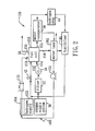
- the heat waste recirculating and cooling system 160 is mainly for use with a fuel cell generating system (fuel cell) 150 using metal hydride as an anode gas (hydrogen) supply 122.
- the fuel cell generating system 150 comprises: a fuel cell 50 having an anode gas inplet152 connected to a hydrogen supply 122; a cathode gas inlet connected to the atmospheric air; an electrical power outlet 156, a heat waste inlet 154, and a coolant inlet 159.
- the heat waste recirculation and cooling system 160 includes: a water tank 162 connected to the heat waste outlet 158, for using heat waste generated by the fuel cell 150 after reaction to heat the water within the water tank 162; a heat exchanger 164 covering and in thermal connective communication with the anode gas supply (hydrogen supply) 122; and a pump 163 provided between the heat tank 162 and the heat exchanger 164 for pumping the hot water to the heat exchanger 164, whereby heat energy of the hot water is used to heat the metal hydride within the anode gas supply 122 for releasing anode gas at a constant pressure, wherein water upon releasing the heat energy is transported back to the fuel cell 50 to reduce the temperature of the fuel cell 50, thereby maintaining the fuel cell 50 at a lower operative temperature for an effective reaction.
- a water tank 162 connected to the heat waste outlet 158, for using heat waste generated by the fuel cell 150 after reaction to heat the water within the water tank 162
- a heat exchanger 164 covering and in thermal connective communication
- excessive air upon reaction within the fuel cell 150, is discharged into a water recuperator 36 through a cathode gas outlet 155.
- the water recuperator 36 may recuperate a minute amount of water contained within the discharged air, where the water is then guided to the water tank 162.
- Excessive hydrogen upon reaction within the fuel cell 150, is pumped by a hydrogen pump 44 to a humidifier 46 through an anode gas outlet 163 to humidify the excessive hydrogen.
- the de-humidified, excessive hydrogen then flows back into the piping of the hydrogen supply to be mixed with fresh hydrogen, and then repeats the same circulation.
- Fig. 3 illustrates a heat exchanger 164 and a water tank 162 for use in this invention.
- the heater exchanger 164 includes: a plurality of water routes 1642 flowing around the hydrogen supply 122, the water routes 1642 being in fluid communication with the water tank 162 such that the hot water may flow around the hydrogen supply 122 through the water routes 1642.
- the hot water exits the water tank 162 from a water outlet 166 located at a lower end of the water tank 162, and is then pumped into the water routes 1642 through a plurality of water inlets 167 formed at a lower end of the heat exchanger 164, and then exits the water routes 164 through a plurality of water outlets 168 located at a lower end of the plate 128.
- heat energy of the hot water is conducted to the hydrogen supply 122.
- the process of releasing hydrogen from the hydrogen,supply 122 is an endothermic reaction.
- the heat energy of the hot water properly serves the purpose required for the endothermic reaction, such that the metal hydride within the hydrogen supply may discharge hydrogen at a selected temperature and at a corresponding pressure.
- One may implement an electronic control circuit, temperature sensors, or other conventional means to control the heating device, so as to maintain a pre-determined temperature.
- a radiator 170 may further be provided between the heat exchanger 164 and the coolant inlet 159 of the fuel cell 150 for further reducing the temperature of the water leaving the heat exchanger 164 and transforming the hot water into coolant, to serve as cooling means for the fuel cell 159.
- part of the hot water prior to entering the heater exchanger 164, may be guided to the humidifier 46 for humidifying excessive hydrogen, while part of the hot water may be guided to a deionized filtering device (not shown) to form a sub-circulation of purified water, thereby optimizing the entire cooling circulation without contaminating the fuel cell 50.
- the heat waste generated from the fuel cell 50 is used to discharge hydrogen stored in the hydrogen supply, while transforming the hot water, a bi-product of the electrochemical reaction of the fuel cell, into coolant required by the fuel cell 50, thereby reducing component cost, reducing electrical energy that may be required by the fuel cell, generating system 150 and enhancing the generating efficiency of the entire system.
Landscapes
- Life Sciences & Earth Sciences (AREA)
- Engineering & Computer Science (AREA)
- Manufacturing & Machinery (AREA)
- Sustainable Development (AREA)
- Sustainable Energy (AREA)
- Chemical & Material Sciences (AREA)
- Chemical Kinetics & Catalysis (AREA)
- Electrochemistry (AREA)
- General Chemical & Material Sciences (AREA)
- Fuel Cell (AREA)
Applications Claiming Priority (2)
| Application Number | Priority Date | Filing Date | Title |
|---|---|---|---|
| CN01124225A CN1405911A (zh) | 2001-08-16 | 2001-08-16 | 燃料电池发电系统及其废热循环冷却系统 |
| CN01124225 | 2001-08-16 |
Publications (2)
| Publication Number | Publication Date |
|---|---|
| EP1284515A2 true EP1284515A2 (de) | 2003-02-19 |
| EP1284515A3 EP1284515A3 (de) | 2004-08-11 |
Family
ID=4665593
Family Applications (1)
| Application Number | Title | Priority Date | Filing Date |
|---|---|---|---|
| EP02014821A Withdrawn EP1284515A3 (de) | 2001-08-16 | 2002-07-03 | Gaserzeugungssystem für eine Brennstoffzelle und Abwärme-Rückführung und Kühlsystem für dieses Erzeugungssystem |
Country Status (2)
| Country | Link |
|---|---|
| EP (1) | EP1284515A3 (de) |
| CN (1) | CN1405911A (de) |
Cited By (3)
| Publication number | Priority date | Publication date | Assignee | Title |
|---|---|---|---|---|
| EP1956671A1 (de) * | 2007-02-02 | 2008-08-13 | Electro Power Systems S.p.A. | Elektrischer Generator für Brennstoffzellen mit einem integrierten Metallhydridspeichersystem |
| CN109378498A (zh) * | 2018-10-23 | 2019-02-22 | 格罗夫汽车科技有限公司 | 一种用于新能源汽车的燃料电池热管理系统 |
| US12486796B2 (en) | 2021-05-20 | 2025-12-02 | Nabors Energy Transition Solutions Llc | Systems and methods for a hydrogen zero emissions vehicle |
Families Citing this family (15)
| Publication number | Priority date | Publication date | Assignee | Title |
|---|---|---|---|---|
| JP4066361B2 (ja) * | 2003-07-30 | 2008-03-26 | トヨタ自動車株式会社 | 燃料電池の冷却システム |
| CN100437101C (zh) * | 2004-01-16 | 2008-11-26 | 亚太燃料电池科技股份有限公司 | 水冷式燃料电池系统组件的检测及功能验证机组 |
| WO2006088053A1 (ja) * | 2005-02-18 | 2006-08-24 | Matsushita Electric Industrial Co., Ltd. | 燃料電池システム及びその運転方法 |
| CN100461514C (zh) * | 2005-12-31 | 2009-02-11 | 山东理工大学 | 直接二甲醚燃料电池系统 |
| CN102610838B (zh) * | 2012-03-22 | 2014-10-15 | 中国东方电气集团有限公司 | 燃料电池热管理系统、燃料电池系统及具有该系统的车辆 |
| CN102800882B (zh) * | 2012-09-07 | 2014-08-27 | 湖北长海新能源科技有限公司 | 一种燃料电池发电系统 |
| CN104577163B (zh) * | 2014-12-01 | 2017-06-06 | 广东合即得能源科技有限公司 | 一种氢气发电系统及其发电方法 |
| CN106450378B (zh) * | 2016-11-22 | 2019-05-03 | 中车株洲电力机车有限公司 | 一种电动车辆及其燃料电池 |
| CN108123163B (zh) * | 2016-11-26 | 2020-09-25 | 中国科学院大连化学物理研究所 | 一种高比能量航空用燃料电池发电装置及控制方法 |
| CN108123162B (zh) * | 2016-11-26 | 2021-02-19 | 中国科学院大连化学物理研究所 | 一种以液氢为燃料的燃料电池发电系统 |
| KR102274017B1 (ko) * | 2017-02-15 | 2021-07-06 | 현대자동차 주식회사 | 연료전지 자동차용 열관리 시스템 |
| CN109256576A (zh) * | 2018-08-13 | 2019-01-22 | 浙江润涞科技服务有限公司 | 一种环保型氢燃料电池系统 |
| CN110474070A (zh) * | 2019-08-19 | 2019-11-19 | 江苏集萃安泰创明先进能源材料研究院有限公司 | 一种固态储氢供氢燃料电池系统 |
| CN111714975B (zh) * | 2020-06-10 | 2021-11-23 | 浙江工业大学 | 一种车载燃料电池的板式进气净化器、进气系统及方法 |
| KR20230089655A (ko) * | 2021-12-14 | 2023-06-21 | 현대자동차주식회사 | 탈수소화 반응 장치 및 이를 포함하는 탈수소화 반응 시스템 |
Family Cites Families (4)
| Publication number | Priority date | Publication date | Assignee | Title |
|---|---|---|---|---|
| JPS60207256A (ja) * | 1984-03-30 | 1985-10-18 | Hitachi Ltd | 燃料電池発電システム |
| JP3583857B2 (ja) * | 1996-03-26 | 2004-11-04 | 三洋電機株式会社 | 水素貯蔵利用装置 |
| EP1175707B1 (de) * | 1999-04-20 | 2003-03-19 | Zentrum für Sonnenenergie- und Wasserstoff-Forschung Baden-Württemberg Gemeinnützige Stiftung | Netzunabhängige, schadstoffemissionsfreie, portable stromversorgungseinrichtung sowie verfahren zur erzeugung von strom mittels dieser |
| DE10061949A1 (de) * | 1999-12-15 | 2001-06-21 | Denso Corp | Abgas-Wärmetauscher |
-
2001
- 2001-08-16 CN CN01124225A patent/CN1405911A/zh active Pending
-
2002
- 2002-07-03 EP EP02014821A patent/EP1284515A3/de not_active Withdrawn
Cited By (3)
| Publication number | Priority date | Publication date | Assignee | Title |
|---|---|---|---|---|
| EP1956671A1 (de) * | 2007-02-02 | 2008-08-13 | Electro Power Systems S.p.A. | Elektrischer Generator für Brennstoffzellen mit einem integrierten Metallhydridspeichersystem |
| CN109378498A (zh) * | 2018-10-23 | 2019-02-22 | 格罗夫汽车科技有限公司 | 一种用于新能源汽车的燃料电池热管理系统 |
| US12486796B2 (en) | 2021-05-20 | 2025-12-02 | Nabors Energy Transition Solutions Llc | Systems and methods for a hydrogen zero emissions vehicle |
Also Published As
| Publication number | Publication date |
|---|---|
| EP1284515A3 (de) | 2004-08-11 |
| CN1405911A (zh) | 2003-03-26 |
Similar Documents
| Publication | Publication Date | Title |
|---|---|---|
| US6692852B2 (en) | Generating system for a fuel cell, and heat waste recirculating and cooling system of said generating system | |
| EP1284515A2 (de) | Gaserzeugungssystem für eine Brennstoffzelle und Abwärme-Rückführung und Kühlsystem für dieses Erzeugungssystem | |
| CN101589498B (zh) | 燃料电池热交换系统和方法 | |
| US6699612B2 (en) | Fuel cell power plant having a reduced free water volume | |
| CN107819141B (zh) | 集成燃料电池系统 | |
| CN114765266B (zh) | 一种提高热效率并优化水管理的sofc热电联供系统 | |
| RU2334309C1 (ru) | Модульная топливно-элементная система | |
| CN112635793A (zh) | 一种双堆双循环的燃料电池系统 | |
| CN112582642A (zh) | 一种燃料电池供氢及回氢的保温加热装置 | |
| US7037610B2 (en) | Humidification of reactant streams in fuel cells | |
| EP1284514A2 (de) | Rückführungssystem von dem Anodestrom einer Brennstoffzelle | |
| JP2016515190A (ja) | 加熱設備および加熱設備の動作方法 | |
| CN119943989B (zh) | 一种热量自平衡的燃料电池发电系统及方法 | |
| JP2001068135A (ja) | 燃料電池用改質システム | |
| US12126061B1 (en) | Ammonia-based solid oxide fuel cell (SOFC) system in which temperature rise using heating element is applied, and operation method therefor | |
| CN116864739A (zh) | 一种水热自平衡和气体湿度可调的燃料电池加湿系统 | |
| CN103259029A (zh) | 燃料电池发电系统 | |
| CN223941791U (zh) | 一种热电联产装置 | |
| CN205579973U (zh) | 一种船载热泵热水器系统 | |
| CN119133515B (zh) | 一种船舶甲醇发动机与燃料电池的热电联产系统及控制方法 | |
| CN117154133B (zh) | 一种船用燃料电池综合热管理系统 | |
| CN218498107U (zh) | 一种固体氧化物燃料电池余热利用系统 | |
| CN111446470B (zh) | 一种燃料电池冷却系统、氢燃料电池及氢燃料电池发动机 | |
| CN119340423A (zh) | 一种具有除盐增湿功能的船用燃料电池系统 | |
| JP2025119405A (ja) | 水電解装置 |
Legal Events
| Date | Code | Title | Description |
|---|---|---|---|
| PUAI | Public reference made under article 153(3) epc to a published international application that has entered the european phase |
Free format text: ORIGINAL CODE: 0009012 |
|
| AK | Designated contracting states |
Designated state(s): AT BE BG CH CY CZ DE DK EE ES FI FR GB GR IE IT LI LU MC NL PT SE SK TR |
|
| AX | Request for extension of the european patent |
Extension state: AL LT LV MK RO SI |
|
| PUAL | Search report despatched |
Free format text: ORIGINAL CODE: 0009013 |
|
| AK | Designated contracting states |
Kind code of ref document: A3 Designated state(s): AT BE BG CH CY CZ DE DK EE ES FI FR GB GR IE IT LI LU MC NL PT SE SK TR |
|
| AX | Request for extension of the european patent |
Extension state: AL LT LV MK RO SI |
|
| RIC1 | Information provided on ipc code assigned before grant |
Ipc: 7H 01M 8/06 B Ipc: 7H 01M 8/04 A |
|
| 17P | Request for examination filed |
Effective date: 20050114 |
|
| AKX | Designation fees paid |
Designated state(s): AT BE BG CH CY CZ DE DK EE ES FI FR GB GR IE IT LI LU MC NL PT SE SK TR |
|
| 17Q | First examination report despatched |
Effective date: 20050527 |
|
| STAA | Information on the status of an ep patent application or granted ep patent |
Free format text: STATUS: THE APPLICATION HAS BEEN WITHDRAWN |
|
| 18W | Application withdrawn |
Effective date: 20050907 |