EP1284517B1 - Combinaison de cellules à combustible - Google Patents
Combinaison de cellules à combustible Download PDFInfo
- Publication number
- EP1284517B1 EP1284517B1 EP01119549.2A EP01119549A EP1284517B1 EP 1284517 B1 EP1284517 B1 EP 1284517B1 EP 01119549 A EP01119549 A EP 01119549A EP 1284517 B1 EP1284517 B1 EP 1284517B1
- Authority
- EP
- European Patent Office
- Prior art keywords
- fuel cell
- electrolyte
- anode
- water
- cathode
- Prior art date
- Legal status (The legal status is an assumption and is not a legal conclusion. Google has not performed a legal analysis and makes no representation as to the accuracy of the status listed.)
- Expired - Lifetime
Links
- 239000000446 fuel Substances 0.000 title claims description 112
- 239000003792 electrolyte Substances 0.000 claims description 81
- 239000000126 substance Substances 0.000 claims description 26
- 239000007795 chemical reaction product Substances 0.000 claims description 25
- 239000000203 mixture Substances 0.000 claims description 23
- 239000002253 acid Substances 0.000 claims description 16
- 238000000034 method Methods 0.000 claims description 9
- 239000007800 oxidant agent Substances 0.000 claims description 7
- 239000012528 membrane Substances 0.000 claims description 6
- 230000001590 oxidative effect Effects 0.000 claims description 4
- 238000007599 discharging Methods 0.000 claims description 3
- 230000001427 coherent effect Effects 0.000 claims description 2
- OKKJLVBELUTLKV-UHFFFAOYSA-N Methanol Chemical compound OC OKKJLVBELUTLKV-UHFFFAOYSA-N 0.000 description 82
- XLYOFNOQVPJJNP-UHFFFAOYSA-N water Substances O XLYOFNOQVPJJNP-UHFFFAOYSA-N 0.000 description 62
- 230000002378 acidificating effect Effects 0.000 description 30
- CURLTUGMZLYLDI-UHFFFAOYSA-N Carbon dioxide Chemical compound O=C=O CURLTUGMZLYLDI-UHFFFAOYSA-N 0.000 description 23
- QVGXLLKOCUKJST-UHFFFAOYSA-N atomic oxygen Chemical compound [O] QVGXLLKOCUKJST-UHFFFAOYSA-N 0.000 description 19
- 239000001301 oxygen Substances 0.000 description 19
- 229910052760 oxygen Inorganic materials 0.000 description 19
- 238000002485 combustion reaction Methods 0.000 description 15
- 238000006243 chemical reaction Methods 0.000 description 14
- 229910002092 carbon dioxide Inorganic materials 0.000 description 12
- 239000001569 carbon dioxide Substances 0.000 description 11
- 239000000047 product Substances 0.000 description 9
- 238000011161 development Methods 0.000 description 5
- 230000018109 developmental process Effects 0.000 description 5
- KWYUFKZDYYNOTN-UHFFFAOYSA-M Potassium hydroxide Chemical compound [OH-].[K+] KWYUFKZDYYNOTN-UHFFFAOYSA-M 0.000 description 3
- 230000036571 hydration Effects 0.000 description 3
- 238000006703 hydration reaction Methods 0.000 description 3
- 150000002500 ions Chemical class 0.000 description 3
- 238000000926 separation method Methods 0.000 description 3
- NBIIXXVUZAFLBC-UHFFFAOYSA-N Phosphoric acid Chemical compound OP(O)(O)=O NBIIXXVUZAFLBC-UHFFFAOYSA-N 0.000 description 2
- QAOWNCQODCNURD-UHFFFAOYSA-N Sulfuric acid Chemical compound OS(O)(=O)=O QAOWNCQODCNURD-UHFFFAOYSA-N 0.000 description 2
- 150000001450 anions Chemical class 0.000 description 2
- 150000001768 cations Chemical class 0.000 description 2
- 238000005370 electroosmosis Methods 0.000 description 2
- XLYOFNOQVPJJNP-UHFFFAOYSA-M hydroxide Chemical compound [OH-] XLYOFNOQVPJJNP-UHFFFAOYSA-M 0.000 description 2
- -1 hydroxide anions Chemical class 0.000 description 2
- 239000007788 liquid Substances 0.000 description 2
- 230000003071 parasitic effect Effects 0.000 description 2
- 239000002699 waste material Substances 0.000 description 2
- UFHFLCQGNIYNRP-UHFFFAOYSA-N Hydrogen Chemical compound [H][H] UFHFLCQGNIYNRP-UHFFFAOYSA-N 0.000 description 1
- 230000002776 aggregation Effects 0.000 description 1
- 238000004220 aggregation Methods 0.000 description 1
- 229910000147 aluminium phosphate Inorganic materials 0.000 description 1
- 238000003491 array Methods 0.000 description 1
- 238000001311 chemical methods and process Methods 0.000 description 1
- 230000001609 comparable effect Effects 0.000 description 1
- 230000000295 complement effect Effects 0.000 description 1
- 150000001875 compounds Chemical class 0.000 description 1
- 239000002322 conducting polymer Substances 0.000 description 1
- 229920001940 conductive polymer Polymers 0.000 description 1
- 238000010276 construction Methods 0.000 description 1
- 230000001419 dependent effect Effects 0.000 description 1
- 229910003460 diamond Inorganic materials 0.000 description 1
- 239000010432 diamond Substances 0.000 description 1
- 238000009792 diffusion process Methods 0.000 description 1
- 238000010494 dissociation reaction Methods 0.000 description 1
- 230000005593 dissociations Effects 0.000 description 1
- 238000005755 formation reaction Methods 0.000 description 1
- 239000007789 gas Substances 0.000 description 1
- 230000020169 heat generation Effects 0.000 description 1
- 239000001257 hydrogen Substances 0.000 description 1
- 229910052739 hydrogen Inorganic materials 0.000 description 1
- 230000001788 irregular Effects 0.000 description 1
- 239000000463 material Substances 0.000 description 1
- VUZPPFZMUPKLLV-UHFFFAOYSA-N methane;hydrate Chemical compound C.O VUZPPFZMUPKLLV-UHFFFAOYSA-N 0.000 description 1
- 238000005457 optimization Methods 0.000 description 1
- 239000002244 precipitate Substances 0.000 description 1
- 238000000746 purification Methods 0.000 description 1
- 239000000376 reactant Substances 0.000 description 1
- 238000004064 recycling Methods 0.000 description 1
- 238000006479 redox reaction Methods 0.000 description 1
- 239000007787 solid Substances 0.000 description 1
- 239000008400 supply water Substances 0.000 description 1
- 229910009112 xH2O Inorganic materials 0.000 description 1
Images



Classifications
-
- H—ELECTRICITY
- H01—ELECTRIC ELEMENTS
- H01M—PROCESSES OR MEANS, e.g. BATTERIES, FOR THE DIRECT CONVERSION OF CHEMICAL ENERGY INTO ELECTRICAL ENERGY
- H01M8/00—Fuel cells; Manufacture thereof
- H01M8/04—Auxiliary arrangements, e.g. for control of pressure or for circulation of fluids
-
- H—ELECTRICITY
- H01—ELECTRIC ELEMENTS
- H01M—PROCESSES OR MEANS, e.g. BATTERIES, FOR THE DIRECT CONVERSION OF CHEMICAL ENERGY INTO ELECTRICAL ENERGY
- H01M8/00—Fuel cells; Manufacture thereof
- H01M8/04—Auxiliary arrangements, e.g. for control of pressure or for circulation of fluids
- H01M8/04082—Arrangements for control of reactant parameters, e.g. pressure or concentration
- H01M8/04089—Arrangements for control of reactant parameters, e.g. pressure or concentration of gaseous reactants
- H01M8/04119—Arrangements for control of reactant parameters, e.g. pressure or concentration of gaseous reactants with simultaneous supply or evacuation of electrolyte; Humidifying or dehumidifying
-
- H—ELECTRICITY
- H01—ELECTRIC ELEMENTS
- H01M—PROCESSES OR MEANS, e.g. BATTERIES, FOR THE DIRECT CONVERSION OF CHEMICAL ENERGY INTO ELECTRICAL ENERGY
- H01M8/00—Fuel cells; Manufacture thereof
- H01M8/10—Fuel cells with solid electrolytes
-
- H—ELECTRICITY
- H01—ELECTRIC ELEMENTS
- H01M—PROCESSES OR MEANS, e.g. BATTERIES, FOR THE DIRECT CONVERSION OF CHEMICAL ENERGY INTO ELECTRICAL ENERGY
- H01M8/00—Fuel cells; Manufacture thereof
- H01M8/10—Fuel cells with solid electrolytes
- H01M8/1009—Fuel cells with solid electrolytes with one of the reactants being liquid, solid or liquid-charged
-
- H—ELECTRICITY
- H01—ELECTRIC ELEMENTS
- H01M—PROCESSES OR MEANS, e.g. BATTERIES, FOR THE DIRECT CONVERSION OF CHEMICAL ENERGY INTO ELECTRICAL ENERGY
- H01M8/00—Fuel cells; Manufacture thereof
- H01M8/24—Grouping of fuel cells, e.g. stacking of fuel cells
-
- H—ELECTRICITY
- H01—ELECTRIC ELEMENTS
- H01M—PROCESSES OR MEANS, e.g. BATTERIES, FOR THE DIRECT CONVERSION OF CHEMICAL ENERGY INTO ELECTRICAL ENERGY
- H01M8/00—Fuel cells; Manufacture thereof
- H01M8/24—Grouping of fuel cells, e.g. stacking of fuel cells
- H01M8/2455—Grouping of fuel cells, e.g. stacking of fuel cells with liquid, solid or electrolyte-charged reactants
-
- H—ELECTRICITY
- H01—ELECTRIC ELEMENTS
- H01M—PROCESSES OR MEANS, e.g. BATTERIES, FOR THE DIRECT CONVERSION OF CHEMICAL ENERGY INTO ELECTRICAL ENERGY
- H01M8/00—Fuel cells; Manufacture thereof
- H01M8/24—Grouping of fuel cells, e.g. stacking of fuel cells
- H01M8/249—Grouping of fuel cells, e.g. stacking of fuel cells comprising two or more groupings of fuel cells, e.g. modular assemblies
- H01M8/2495—Grouping of fuel cells, e.g. stacking of fuel cells comprising two or more groupings of fuel cells, e.g. modular assemblies of fuel cells of different types
-
- Y—GENERAL TAGGING OF NEW TECHNOLOGICAL DEVELOPMENTS; GENERAL TAGGING OF CROSS-SECTIONAL TECHNOLOGIES SPANNING OVER SEVERAL SECTIONS OF THE IPC; TECHNICAL SUBJECTS COVERED BY FORMER USPC CROSS-REFERENCE ART COLLECTIONS [XRACs] AND DIGESTS
- Y02—TECHNOLOGIES OR APPLICATIONS FOR MITIGATION OR ADAPTATION AGAINST CLIMATE CHANGE
- Y02E—REDUCTION OF GREENHOUSE GAS [GHG] EMISSIONS, RELATED TO ENERGY GENERATION, TRANSMISSION OR DISTRIBUTION
- Y02E60/00—Enabling technologies; Technologies with a potential or indirect contribution to GHG emissions mitigation
- Y02E60/30—Hydrogen technology
- Y02E60/50—Fuel cells
Definitions
- the invention generally relates to a fuel cell device with a basic electrolyte device and an acidic electrolyte device, wherein a reaction product of an electrolytic device of the other electrolytic device can be fed.
- the invention relates to such a fuel cell device in which the above-mentioned reaction product is H 2 O.
- Fuel cells convert energy stored in the molecular bonds of chemical compounds directly into electrical energy. This "cold combustion” differs from ordinary (“hot”) combustion in that the dissociation and formation reactions underlying the energy conversion (redox reaction) are spatially separate from each other and the conversion of chemical energy into electrical energy does not involve the detour of heat generation and combustion Conversion of heat energy into mechanical work takes place.
- the usable electrical energy of the fuel cell is given by the Gibbs enthalpy ⁇ G of this reaction, and is dependent inter alia on the operating temperature of the fuel cell.
- the structure of a fuel cell consists of an anode-side chamber and a cathode-side chamber by an ion-conducting (liquid or solid) electrolyte are separated from each other.
- anode-side chamber of the (usually hydrogen-containing) fuel is supplied, while the cathode-side chamber of the reactant, usually oxygen is supplied.
- fuel cell reaction products for example. Water and / or carbon dioxide, which may need to be partially or completely removed.
- acidic electrolytes for example sulfuric acid, phosphoric acid
- basic electrolytes for example potassium hydroxide
- the substance mixture [1.5 O 2 + (3 + y) H 2 O] indicated on the cathode side must be proportionally supplied per anode side fed formula unit methanol, wherein the water requirement (3 + y) H 2 O by the on Although the anode resulting larger amount of water (5 + y) H 2 O may in principle be met, the technical realization of proportional water return but as mentioned is associated with high technical difficulties.
- a fuel cell device comprises an electrolyte device, which comprises a basic electrolyte device and an acidic electrolyte device, wherein the fuel cell device is designed such that at least a part of at least one reaction product obtained at one electrolytic device can be supplied to the other electrolytic device.
- the method according to the invention for operating a fuel cell device comprises the steps of providing a basic electrolyte device and an acid electrolyte device, supplying fuel and oxidizing agents, discharging reaction products, wherein at least a part of at least one reaction product obtained at one electrolytic device is supplied to the other electrolytic device.
- At least one reaction product obtained at one electrolytic device can be completely fed to the other electrolytic device.
- a simple embodiment of a fuel cell device according to the invention comprises a basic electrolyte device, which is formed by a single anion-conducting region, and an acid electrolyte device, which is formed by a single cation-conducting region.
- a basic electrolyte device which is formed by a single anion-conducting region
- an acid electrolyte device which is formed by a single cation-conducting region.
- fuel cell devices are not limited to ever a single such area.
- preferred developments of the fuel cell device have an acidic electrolyte device with a plurality of cation-conducting regions and / or a basic electrolyte device with a plurality of anion-conducting regions.
- reaction products pass through the basic and the acid electrolyte means alternately several times in succession, which allows a more complete exploitation of these substances and thus a more efficient operation of the fuel cell apparatus.
- the anion-conducting regions and the cation-conducting regions are arranged alternately.
- the alternating arrangement of the regions can take place along one direction (one-dimensional arrangement) and, for example, form a striped pattern. These areas can all have the same dimensioning, but they can also change in the direction of passage.
- the alternating arrangement takes place in two directions at the same time.
- Preferred two-dimensional arrays of equally sized areas include: checkerboard pattern, diamond pattern, triangular pattern, hexagon pattern.
- a two-dimensional arrangement of different sized areas are any number of possibilities open. These arrangements are optimized in terms of as complete as possible combustion of the supplied fuels and utilization of the resulting reaction products.
- the cathode device of the fuel cell device comprises a single cathode chamber and / or the anode device of the fuel cell device comprises a single anode chamber.
- an electrolyte device which is formed as a continuous structure but has a locally different chemical composition, with regions of different chemical composition forming the cation-conducting regions (i.e., the acidic electrolyte device) and the anion-conducting regions (i.e., the basic electrolyte device).
- the electrolyte device of the fuel cell device comprises an ion-conducting membrane.
- Fuel cell with basic electrolyte Anode: CH 3 OH + 6OH - ⁇ CO 2 + 5H 2 O + 6e - Cathode: 1.5 O 2 + (3 + y) H 2 O + 6e - ⁇ (6OH - + yH 2 O) total [CH 3 OH] + ⁇ 1.5 O 2 + (3 + y) H 2 O ⁇ ⁇ [CO 2 ] + ⁇ (5 + y) H 2 O ⁇
- FIG. 1 describes a fuel cell device 100 according to the invention, which is constructed from a combination of two substantially separate fuel cells 100B and 100S.
- One of these two fuel cells has a basic electrolyte 110B, and the second fuel cell has an acidic electrolyte 110S.
- each of the two fuel cells may be formed as a fuel cell stack.
- the two electrolytes 110B, 110S form the electrolyte device 110 of the combined fuel cell device 100.
- both fuel cells 100B, 100S the same oxidant 2 is supplied to the cathode chambers 130 at the respective anode chamber 120 of the fuel 1 identical to both fuel cells. From the Kathodenkammem the combustion product 4 is further removed.
- fuel 1 is methanol and oxidant 2 is oxygen, for example an oxygen-containing gas mixture, such as air.
- oxygen-containing gas mixture such as air.
- the combustion product 4 is carbon dioxide.
- the basic electrolytic device 110 B must be next to the oxidizing agent 2, d. H. Oxygen according to the above-mentioned cathode equation nor a certain amount of water 6 are supplied, which is necessary for the course of the reactions in the fuel cell. At the same time, however, water also emerges on the anode side again: partially newly formed as a consequence of the chemical processes that are taking place, in part due to diffusion through the electrolyte. Without distinguishing these processes, the term reaction product is used for this purpose.
- the two fuel cells 100S and 100B are combined to form a fuel cell device 100 by supplying the anode side exiting reaction product 3 (here: water) to the anode chamber 120 of the acidic fuel cell 100S.
- anode side exiting reaction product 3 here: water
- anode chamber 120 of the acidic fuel cell 100S it forms the anode-side methanol / water mixture required for the operation of an acidic electrolyte device with the simultaneously supplied fuel methanol 1.
- the reaction product 3 transferred from one anode chamber into the other anode chamber need not be subjected to expensive purification processes. Rather, the reaction product 3 (water) may well with the other substances, i. the fuel 1 (methanol) and the combustion product 4 (carbon dioxide) be "contaminated", without affecting the operation of the device.
- FIG. 1 has the advantage over a water return from the anode chamber into the cathode chamber (or vice versa) of a conventional fuel cell that no complex separation of substances must be performed.
- the substances methanol 1, water 3, and carbon dioxide 4 are present in the anode chamber 120 of the basic fuel cell 10OB.
- the same substances are also present in the acidic fuel cell, wherein, in contrast to the basic fuel cell, water is not obtained as a reaction product, but rather is required to achieve the desired reaction.
- the water can be transferred from the anode chamber of the basic fuel cell in the anode chamber of the acidic fuel cell, without causing a need to clean unwanted substances.
- FIG. 2 shows another embodiment of a fuel cell apparatus 200 made of a combination of a basic fuel cell and an acid fuel cell.
- the fuel cell combination described now has no external water supply. Instead, part 3 'of the water accumulating on the cathode side 230 in the case of the "acidic fuel cell" 200S is transferred into the cathode chamber 230 of the "basic fuel cell” 200B. By supplying oxygen 2, the oxygen / water mixture required for forming the hydroxide anions is formed in this chamber 230.
- the hydroxide anions diffuse through the basic electrolyte 210B, surrounding themselves with a hydration shell.
- the water 3 thus transported into the anode chamber 220 is now transported together with the water 3 and carbon dioxide 4 accumulating during the actual combustion of the methanol into the anode chamber 220 of the acidic fuel cell 200S.
- the carbon dioxide 4 is withdrawn, for example, by external removal of the further transport and reaction processes, while the water 3 together with the supplied fuel 1 to the operating he acidic fuel cell 200S required water / methanol mixture results.
- FIG. 3 shows a further embodiment of the fuel cell device 300 according to the invention, which is now in contrast to the in FIGS. 1 and 2 shown embodiments is no longer composed of two more or less separately functional fuel cells.
- FIG. 3 a fuel cell device 300, which comprises a basic electrolyte device 310B and an acidic electrolyte device 310S, which have a common anode chamber 320.
- an oxygen / water mixture indicated by reference numerals 2 and 6 is supplied into the cathode chamber 230.
- the anode chamber 320 is fed with pure methanol.
- the common anode chamber 320 it is not necessary to externally supply water to the anode chamber. Instead, the methanol / water mixture formed in the anode chamber 320 can be used to operate the subsequent acidic electrolyte device 310S if oxygen is supplied to the acidic electrolyte device 310S on the cathode side 330.
- the excess water 5 accumulated in the overall process is removed from the cathode chamber 330 of the acid electrolyte device 310S.
- the electrolyte device 410 has two adjacent electrolytic devices 410S, 410B, of which one electrolytic device 410B has a basic character, the other electrolytic device 410S has an acidic character.
- the fuel cell device 400 is configured such that the two electrolytic devices 410B and 410S each have a common cathode chamber 430 and a common anode chamber 420. Thus, only one fuel 1 feeder and one oxygen feeder 2 is required.
- the anode-side accumulating water 3 in operation in the basic electrolytic device 410B forms with the anode-side supplied methanol 1, a methanol / water mixture, which is used for the combustion process in the acidic electrolyzer 410S.
- a part of the water 3 'accumulating on the acidic electrolyte means 410S on the cathode side may form the cathode-side water / oxygen mixture required to operate the basic fuel cell device 400.
- the excess water 5 is removed on the cathode side.
- FIG. 5 shows a similar embodiment as FIG. 4 , where now one of the two electrolytic devices 510S, 510B, namely the acid electrolyte device 510S comprises two separate regions, between which the basic electrolytic device 510B is provided.
- This embodiment is operated similarly to those in FIG. 4 described embodiment:
- Water 3 which accumulates the methanol 1 supplied to the anode chamber 520 and forms an anode-side methanol / water mixture necessary for the operation of the acidic electrolyte devices 510S, is produced from the centrally provided basic electrolyte device 510B on the anode side. Similarly, the water 3 discharging on the acidic electrolyte means 510S on the cathode side mixes with the oxygen 2 supplied on the cathode side, thereby forming the cathode-side water / oxygen mixture required for the basic electrolyte means 510B.
- FIG. 6 shows a further preferred embodiment of the fuel cell device 600 according to the invention, which comprises a plurality of alternately arranged electrolyte devices 610S and 610B. These alternatingly arranged regions form the electrolyte device 610 of the fuel cell device 600, which has a single, common anode chamber 620 and a single, common cathode chamber 630.
- the arrangement is such that at one input side of the common anode chamber 620, the fuel 1 is supplied flows past the anode sides of the successively arranged electrolytic devices 610S, 610B. Similarly, oxygen 2 is introduced on one side of the cathode chamber 630.
- part of the methanol 1 burns on the anode side to form carbon dioxide 4, and water 3 additionally precipitates above the basic electrolyte regions 610B.
- the resulting methanol / water mixture can be used to operate the adjacent 610S acidic electrolyte regions.
- anode chamber 620 In the anode chamber 620, a total of one methanol depletion takes place in the flow direction, while on the cathode side an oxygen depletion of the present oxygen / water mixture takes place.
- FIG. 6 has individual, separate elements of the electrolytic device.
- FIG. 7 shows FIG. 7 an alternative and particularly preferred embodiment of an electrolytic device 710, the electrolytic device 610 in the embodiment of FIG. 6 can replace.
- electrolytic device 710 of FIG. 7 There are no mutually isolable electrolytic devices, but a coherent structure with locally different chemical composition.
- the composition was chosen in each case such that regions with cation conduction and regions with anion conduction alternate, resulting in an electrolytic device 710 in which acidic regions S and basic regions B alternate.
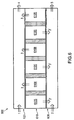
- FIG. 8 shows, such an alternating arrangement along a direction, for. B. along the x-axis, extend.
- the dimensioning of the areas is freely selectable and not limited to the example shown schematically with approximately equal areas.
- FIG. 9 shows, the alternating arrangement, but can also be done along two spatial directions, and, for example, give a checkerboard pattern. Continuous arrangements such as triangular patterns or irregular patterns are also within the scope of this invention.
Landscapes
- Life Sciences & Earth Sciences (AREA)
- Engineering & Computer Science (AREA)
- Manufacturing & Machinery (AREA)
- Sustainable Development (AREA)
- Sustainable Energy (AREA)
- Chemical & Material Sciences (AREA)
- Chemical Kinetics & Catalysis (AREA)
- Electrochemistry (AREA)
- General Chemical & Material Sciences (AREA)
- Fuel Cell (AREA)
Claims (9)
- Système de pile ou cellule à combustible (100, 200) avec un système d'électrolyte (110, 210), qui comprend un dispositif d'électrolyte basique (110B, 210B) et un dispositif d'électrolyte acide (110S, 210S), le système de pile à combustible (100, 200) étant configuré de manière qu'au moins une partie d'au moins un produit de réaction, qui est engendré au niveau d'un dispositif d'électrolyte (110B; 210B, 210S), puisse être amené à l'autre dispositif d'électrolyte (110S; 210S, 210B),
système de pile à combustible dans lequel le dispositif d'électrolyte basique (110B, 210B) comprend au moins une zone conduisant les anions, et le dispositif d'électrolyte acide (110S, 210S) comprend au moins une zone conduisant les cations. - Système de pile à combustible (100, 200) selon la revendication 1, dans lequel au moins un produit de réaction (3) engendré au niveau dudit un dispositif d'électrolyte (110B, 210B) peut être amené en totalité à l'autre dispositif d'électrolyte (110S, 210S).
- Système de pile à combustible (500, 600, 700) selon l'une des revendications précédentes, dans lequel le dispositif d'électrolyte acide (510S, 610S, 710S) comprend une pluralité de zones conduisant les cations.
- Système de pile à combustible (600, 700) selon l'une des revendications précédentes, dans lequel le dispositif d'électrolyte basique (610B, 710B) comprend une pluralité de zones conduisant les anions.
- Système de pile à combustible (500, 600, 700) selon l'une des revendications 1 à 4, dans lequel des zones conduisant les anions et des zones conduisant les cations sont agencées de manière alternée.
- Système de pile à combustible (300, 400, 500, 600, 700) selon l'une des revendications précédentes, comprenant un système de cathode (320, 520, 620, 720), qui comprend une seule chambre de cathode, et/ou un système d'anode (430, 530, 630, 730), qui comprend une seule chambre d'anode.
- Système de pile à combustible (700) selon l'une des revendications 1 à 6, dans lequel le système d'électrolyte (710) est une structure continue d'un seul tenant avec une composition chimique localement différente, des zones de composition chimique différente formant les zones basique (B) et les zones acides (S).
- Système de pile à combustible (100 - 700) selon l'une des revendications précédentes, dans lequel le système d'électrolyte (110 - 710) comprend une membrane.
- Procédé pour faire fonctionner un système de pile à combustible (100), comprenant les étapes :fourniture et préparation d'un dispositif d'électrolyte (110B) avec au moins une zone conduisant les anions, et d'un dispositif d'électrolyte (110S) avec au moins une zone conduisant les cations,amenée d'au moins un combustible (1) et d'au moins un agent d'oxydation (2),évacuation de produits de réaction (1, 3, 4, 5), au moins une partie d'au moins un produit de réaction (3), qui est engendré au niveau d'un dispositif d'électrolyte (110B), étant amené à l'autre dispositif d'électrolyte (110S).
Priority Applications (7)
| Application Number | Priority Date | Filing Date | Title |
|---|---|---|---|
| ES01119549.2T ES2563453T3 (es) | 2001-08-14 | 2001-08-14 | Combinación de pilas de combustible |
| EP01119549.2A EP1284517B1 (fr) | 2001-08-14 | 2001-08-14 | Combinaison de cellules à combustible |
| KR10-2004-7002200A KR100517669B1 (ko) | 2001-08-14 | 2002-08-12 | 연료 전지 조합 |
| US10/486,872 US7435505B2 (en) | 2001-08-14 | 2002-08-12 | Fuel cell combination |
| JP2003522203A JP3839812B2 (ja) | 2001-08-14 | 2002-08-12 | 燃料電池コンビネーション |
| PCT/EP2002/009020 WO2003017406A1 (fr) | 2001-08-14 | 2002-08-12 | Combinaison de piles a combustible |
| CA002456867A CA2456867C (fr) | 2001-08-14 | 2002-08-12 | Combinaison de piles a combustible |
Applications Claiming Priority (1)
| Application Number | Priority Date | Filing Date | Title |
|---|---|---|---|
| EP01119549.2A EP1284517B1 (fr) | 2001-08-14 | 2001-08-14 | Combinaison de cellules à combustible |
Publications (2)
| Publication Number | Publication Date |
|---|---|
| EP1284517A1 EP1284517A1 (fr) | 2003-02-19 |
| EP1284517B1 true EP1284517B1 (fr) | 2016-02-03 |
Family
ID=8178323
Family Applications (1)
| Application Number | Title | Priority Date | Filing Date |
|---|---|---|---|
| EP01119549.2A Expired - Lifetime EP1284517B1 (fr) | 2001-08-14 | 2001-08-14 | Combinaison de cellules à combustible |
Country Status (7)
| Country | Link |
|---|---|
| US (1) | US7435505B2 (fr) |
| EP (1) | EP1284517B1 (fr) |
| JP (1) | JP3839812B2 (fr) |
| KR (1) | KR100517669B1 (fr) |
| CA (1) | CA2456867C (fr) |
| ES (1) | ES2563453T3 (fr) |
| WO (1) | WO2003017406A1 (fr) |
Families Citing this family (8)
| Publication number | Priority date | Publication date | Assignee | Title |
|---|---|---|---|---|
| EP1650824A1 (fr) * | 2004-10-25 | 2006-04-26 | SFC Smart Fuel Cell AG | Combinaison de piles à combustible avec un régime hydrique autonome |
| US20070259236A1 (en) * | 2006-05-03 | 2007-11-08 | Lang Christopher M | Anionic fuel cells, hybrid fuel cells, and methods of fabrication thereof |
| US20080292918A1 (en) * | 2007-05-25 | 2008-11-27 | Caine Finnerty | Electrochemical system having multiple independent circuits |
| KR101040864B1 (ko) * | 2007-10-30 | 2011-06-14 | 삼성에스디아이 주식회사 | 유체 회수장치 및 이를 채용한 연료전지 시스템 |
| US20110151349A1 (en) * | 2008-06-10 | 2011-06-23 | Technion Research & Development Foundation Ltd. | Double-electrolyte fuel-cell |
| EP2481114A1 (fr) * | 2009-09-24 | 2012-08-01 | Georgia Tech Research Corporation | Dispositifs électromécaniques basés sur des membranes à conduction ionique à jonctions multiples |
| WO2012177255A1 (fr) | 2011-06-23 | 2012-12-27 | Utc Power Corporation | Configuration de champ d'écoulement pour plaque de pile à combustible |
| DE102012017598A1 (de) * | 2012-09-06 | 2014-03-06 | Volkswagen Aktiengesellschaft | Polymerelektrolytmembran für eine Brennstoffzelle, sowie Membran-Elektroden-Einheit und Brennstoffzelle mit einer solchen |
Family Cites Families (8)
| Publication number | Priority date | Publication date | Assignee | Title |
|---|---|---|---|---|
| US314340A (en) * | 1885-03-24 | Brick-machine | ||
| US3143440A (en) | 1960-08-04 | 1964-08-04 | Hunger Herbert | Fuel cell |
| DE3800484A1 (de) * | 1988-01-11 | 1989-07-20 | Rudolf Prof Dr Schulten | Duale aufladbare elektrische batterien |
| US5846669A (en) * | 1994-05-12 | 1998-12-08 | Illinois Institute Of Technology | Hybrid electrolyte system |
| US6329094B1 (en) * | 1997-05-14 | 2001-12-11 | Sanyo Electric Co., Ltd. | Polymer electrolyte fuel cell showing stable and outstanding electric-power generating characteristics |
| CA2378242A1 (fr) * | 1999-07-05 | 2001-01-11 | Siemens Aktiengesellschaft | Installation de pile a combustible et procede pour operer ladite insrallation |
| DE19930877C2 (de) * | 1999-07-05 | 2003-05-15 | Siemens Ag | Brennstoffzellenanlage und Verfahren zum Betreiben dieser Brennstoffzellenanlage |
| DE10007652A1 (de) | 2000-02-19 | 2001-09-06 | Forschungszentrum Juelich Gmbh | Brennstoffzelle |
-
2001
- 2001-08-14 EP EP01119549.2A patent/EP1284517B1/fr not_active Expired - Lifetime
- 2001-08-14 ES ES01119549.2T patent/ES2563453T3/es not_active Expired - Lifetime
-
2002
- 2002-08-12 US US10/486,872 patent/US7435505B2/en not_active Expired - Lifetime
- 2002-08-12 KR KR10-2004-7002200A patent/KR100517669B1/ko not_active Expired - Lifetime
- 2002-08-12 CA CA002456867A patent/CA2456867C/fr not_active Expired - Lifetime
- 2002-08-12 WO PCT/EP2002/009020 patent/WO2003017406A1/fr not_active Ceased
- 2002-08-12 JP JP2003522203A patent/JP3839812B2/ja not_active Expired - Fee Related
Also Published As
| Publication number | Publication date |
|---|---|
| US7435505B2 (en) | 2008-10-14 |
| CA2456867A1 (fr) | 2003-02-27 |
| KR100517669B1 (ko) | 2005-09-28 |
| EP1284517A1 (fr) | 2003-02-19 |
| ES2563453T3 (es) | 2016-03-15 |
| CA2456867C (fr) | 2008-09-23 |
| JP3839812B2 (ja) | 2006-11-01 |
| WO2003017406A1 (fr) | 2003-02-27 |
| KR20040036708A (ko) | 2004-04-30 |
| JP2005500659A (ja) | 2005-01-06 |
| US20050069757A1 (en) | 2005-03-31 |
Similar Documents
| Publication | Publication Date | Title |
|---|---|---|
| DE1557065C3 (de) | Verfahren zum Reinigen eines Wasserstoff oder Sauerstoff enthaltenden Gases | |
| EP0068522B1 (fr) | Procédé et installation pour la préparation synthétique d'ozone par electrolyse et son application | |
| DE69107992T2 (de) | Verfahren zur elektrolytischen Herstellung von Ozon und Vorrichtung dazu. | |
| DE602004009180T2 (de) | Strömungsfeldplattengeometrien | |
| EP0596366B1 (fr) | Procédé et dispositif pour évacuation de l'eau et des gaz inertes dans une batterie de piles à combustible | |
| DE69232293T2 (de) | Anordnung für leichte brennstoffzellenmembranelektrode mit integralen durchflüssen für den reaktanten | |
| DE60105811T2 (de) | Vorrichtung für elektrodeionisation | |
| EP0762927A1 (fr) | Cellules electrolytiques simples et multiples et groupements de telles cellules destines a la desionisation de milieux aqueux | |
| EP1407506A2 (fr) | Procede et dispositif pour la desionisation de milieux refrigerants pour des piles a combustible | |
| EP0168600B1 (fr) | Electrolyseur bipolaire avec cathode à diffusion de gaz | |
| EP1284517B1 (fr) | Combinaison de cellules à combustible | |
| EP0095997A1 (fr) | Procédé pour la production de l'eau oxygénée et son utilisation | |
| WO2015128076A1 (fr) | Procédé de fabrication électrochimique d'eau électrolysée | |
| EP3526372B1 (fr) | Cellule électrolytique ayant une électrode à diffusion gazeuse et son procédé de fonctionnement | |
| EP0058784B1 (fr) | Procédé de production continue d'oxyde d'azote (NO) | |
| DE1571730A1 (de) | Elektrochemische Zellenanordnung | |
| EP0463438A1 (fr) | Production d'acide chromique avec utilisation de membranes bipolaires | |
| EP1327277B1 (fr) | Installation a piles a combustible | |
| DE102018202337A1 (de) | Elektrochemische Herstellung eines Gases umfassend CO mit Zwischenkühlung des Elektrolytstroms | |
| WO2006092125A1 (fr) | Systeme pour desinfecter des liquides a faible conductibilite | |
| DE10129190A1 (de) | Brennstoffzelle | |
| DE102008052945A1 (de) | Brennstoffzellenstapel | |
| DE102020208604B4 (de) | Energiewandlungssystem | |
| DE60008599T2 (de) | Endkasten für einen elektrodialysator und elektro-dialyse-verfahren | |
| DE60306916T3 (de) | Elektrochemischer generator mit einer bipolarplatte, welche eine vielzahl von der verteilung der gase dienenden löcher aufweist |
Legal Events
| Date | Code | Title | Description |
|---|---|---|---|
| PUAI | Public reference made under article 153(3) epc to a published international application that has entered the european phase |
Free format text: ORIGINAL CODE: 0009012 |
|
| 17P | Request for examination filed |
Effective date: 20020301 |
|
| AK | Designated contracting states |
Designated state(s): AT BE CH CY DE DK ES FI FR GB GR IE IT LI LU MC NL PT SE TR |
|
| AX | Request for extension of the european patent |
Extension state: AL LT LV MK RO SI |
|
| RAP1 | Party data changed (applicant data changed or rights of an application transferred) |
Owner name: SFC SMART FUEL CELL AG |
|
| AKX | Designation fees paid |
Designated state(s): AT BE CH CY DE DK ES FI FR GB GR IE IT LI LU MC NL PT SE TR |
|
| 17Q | First examination report despatched |
Effective date: 20080729 |
|
| RAP1 | Party data changed (applicant data changed or rights of an application transferred) |
Owner name: SFC ENERGY AG |
|
| GRAP | Despatch of communication of intention to grant a patent |
Free format text: ORIGINAL CODE: EPIDOSNIGR1 |
|
| INTG | Intention to grant announced |
Effective date: 20150806 |
|
| GRAS | Grant fee paid |
Free format text: ORIGINAL CODE: EPIDOSNIGR3 |
|
| GRAA | (expected) grant |
Free format text: ORIGINAL CODE: 0009210 |
|
| RIN1 | Information on inventor provided before grant (corrected) |
Inventor name: STEFENER MANFRED Inventor name: MUELLER, DR. JENS |
|
| AK | Designated contracting states |
Kind code of ref document: B1 Designated state(s): AT BE CH CY DE DK ES FI FR GB GR IE IT LI LU MC NL PT SE TR |
|
| REG | Reference to a national code |
Ref country code: GB Ref legal event code: FG4D Free format text: NOT ENGLISH |
|
| REG | Reference to a national code |
Ref country code: AT Ref legal event code: REF Ref document number: 774066 Country of ref document: AT Kind code of ref document: T Effective date: 20160215 Ref country code: CH Ref legal event code: EP |
|
| REG | Reference to a national code |
Ref country code: IE Ref legal event code: FG4D Free format text: LANGUAGE OF EP DOCUMENT: GERMAN |
|
| REG | Reference to a national code |
Ref country code: ES Ref legal event code: FG2A Ref document number: 2563453 Country of ref document: ES Kind code of ref document: T3 Effective date: 20160315 |
|
| REG | Reference to a national code |
Ref country code: DE Ref legal event code: R096 Ref document number: 50116528 Country of ref document: DE |
|
| REG | Reference to a national code |
Ref country code: NL Ref legal event code: MP Effective date: 20160203 |
|
| PG25 | Lapsed in a contracting state [announced via postgrant information from national office to epo] |
Ref country code: GR Free format text: LAPSE BECAUSE OF FAILURE TO SUBMIT A TRANSLATION OF THE DESCRIPTION OR TO PAY THE FEE WITHIN THE PRESCRIBED TIME-LIMIT Effective date: 20160504 Ref country code: FI Free format text: LAPSE BECAUSE OF FAILURE TO SUBMIT A TRANSLATION OF THE DESCRIPTION OR TO PAY THE FEE WITHIN THE PRESCRIBED TIME-LIMIT Effective date: 20160203 |
|
| REG | Reference to a national code |
Ref country code: FR Ref legal event code: PLFP Year of fee payment: 16 |
|
| PG25 | Lapsed in a contracting state [announced via postgrant information from national office to epo] |
Ref country code: NL Free format text: LAPSE BECAUSE OF FAILURE TO SUBMIT A TRANSLATION OF THE DESCRIPTION OR TO PAY THE FEE WITHIN THE PRESCRIBED TIME-LIMIT Effective date: 20160203 Ref country code: PT Free format text: LAPSE BECAUSE OF FAILURE TO SUBMIT A TRANSLATION OF THE DESCRIPTION OR TO PAY THE FEE WITHIN THE PRESCRIBED TIME-LIMIT Effective date: 20160603 Ref country code: SE Free format text: LAPSE BECAUSE OF FAILURE TO SUBMIT A TRANSLATION OF THE DESCRIPTION OR TO PAY THE FEE WITHIN THE PRESCRIBED TIME-LIMIT Effective date: 20160203 |
|
| PG25 | Lapsed in a contracting state [announced via postgrant information from national office to epo] |
Ref country code: DK Free format text: LAPSE BECAUSE OF FAILURE TO SUBMIT A TRANSLATION OF THE DESCRIPTION OR TO PAY THE FEE WITHIN THE PRESCRIBED TIME-LIMIT Effective date: 20160203 |
|
| REG | Reference to a national code |
Ref country code: DE Ref legal event code: R097 Ref document number: 50116528 Country of ref document: DE |
|
| PLBE | No opposition filed within time limit |
Free format text: ORIGINAL CODE: 0009261 |
|
| STAA | Information on the status of an ep patent application or granted ep patent |
Free format text: STATUS: NO OPPOSITION FILED WITHIN TIME LIMIT |
|
| PG25 | Lapsed in a contracting state [announced via postgrant information from national office to epo] |
Ref country code: BE Free format text: LAPSE BECAUSE OF NON-PAYMENT OF DUE FEES Effective date: 20160831 |
|
| 26N | No opposition filed |
Effective date: 20161104 |
|
| PG25 | Lapsed in a contracting state [announced via postgrant information from national office to epo] |
Ref country code: MC Free format text: LAPSE BECAUSE OF FAILURE TO SUBMIT A TRANSLATION OF THE DESCRIPTION OR TO PAY THE FEE WITHIN THE PRESCRIBED TIME-LIMIT Effective date: 20160203 |
|
| REG | Reference to a national code |
Ref country code: CH Ref legal event code: PL |
|
| PG25 | Lapsed in a contracting state [announced via postgrant information from national office to epo] |
Ref country code: LI Free format text: LAPSE BECAUSE OF NON-PAYMENT OF DUE FEES Effective date: 20160831 Ref country code: CH Free format text: LAPSE BECAUSE OF NON-PAYMENT OF DUE FEES Effective date: 20160831 |
|
| REG | Reference to a national code |
Ref country code: IE Ref legal event code: MM4A |
|
| PG25 | Lapsed in a contracting state [announced via postgrant information from national office to epo] |
Ref country code: IE Free format text: LAPSE BECAUSE OF NON-PAYMENT OF DUE FEES Effective date: 20160814 |
|
| REG | Reference to a national code |
Ref country code: FR Ref legal event code: PLFP Year of fee payment: 17 |
|
| PG25 | Lapsed in a contracting state [announced via postgrant information from national office to epo] |
Ref country code: LU Free format text: LAPSE BECAUSE OF NON-PAYMENT OF DUE FEES Effective date: 20160814 |
|
| REG | Reference to a national code |
Ref country code: AT Ref legal event code: MM01 Ref document number: 774066 Country of ref document: AT Kind code of ref document: T Effective date: 20160814 |
|
| PG25 | Lapsed in a contracting state [announced via postgrant information from national office to epo] |
Ref country code: AT Free format text: LAPSE BECAUSE OF NON-PAYMENT OF DUE FEES Effective date: 20160814 |
|
| PG25 | Lapsed in a contracting state [announced via postgrant information from national office to epo] |
Ref country code: CY Free format text: LAPSE BECAUSE OF FAILURE TO SUBMIT A TRANSLATION OF THE DESCRIPTION OR TO PAY THE FEE WITHIN THE PRESCRIBED TIME-LIMIT Effective date: 20160203 |
|
| PG25 | Lapsed in a contracting state [announced via postgrant information from national office to epo] |
Ref country code: TR Free format text: LAPSE BECAUSE OF FAILURE TO SUBMIT A TRANSLATION OF THE DESCRIPTION OR TO PAY THE FEE WITHIN THE PRESCRIBED TIME-LIMIT Effective date: 20160203 |
|
| REG | Reference to a national code |
Ref country code: FR Ref legal event code: PLFP Year of fee payment: 18 |
|
| PGFP | Annual fee paid to national office [announced via postgrant information from national office to epo] |
Ref country code: ES Payment date: 20200902 Year of fee payment: 20 Ref country code: DE Payment date: 20200827 Year of fee payment: 20 Ref country code: FR Payment date: 20200826 Year of fee payment: 20 Ref country code: GB Payment date: 20200826 Year of fee payment: 20 |
|
| PGFP | Annual fee paid to national office [announced via postgrant information from national office to epo] |
Ref country code: IT Payment date: 20200831 Year of fee payment: 20 |
|
| REG | Reference to a national code |
Ref country code: DE Ref legal event code: R071 Ref document number: 50116528 Country of ref document: DE |
|
| REG | Reference to a national code |
Ref country code: GB Ref legal event code: PE20 Expiry date: 20210813 |
|
| PG25 | Lapsed in a contracting state [announced via postgrant information from national office to epo] |
Ref country code: GB Free format text: LAPSE BECAUSE OF EXPIRATION OF PROTECTION Effective date: 20210813 |
|
| REG | Reference to a national code |
Ref country code: ES Ref legal event code: FD2A Effective date: 20220127 |
|
| PG25 | Lapsed in a contracting state [announced via postgrant information from national office to epo] |
Ref country code: ES Free format text: LAPSE BECAUSE OF EXPIRATION OF PROTECTION Effective date: 20210815 |