EP1284521A2 - Pile à combustible avec dispositif de compression uniforme - Google Patents
Pile à combustible avec dispositif de compression uniforme Download PDFInfo
- Publication number
- EP1284521A2 EP1284521A2 EP02003460A EP02003460A EP1284521A2 EP 1284521 A2 EP1284521 A2 EP 1284521A2 EP 02003460 A EP02003460 A EP 02003460A EP 02003460 A EP02003460 A EP 02003460A EP 1284521 A2 EP1284521 A2 EP 1284521A2
- Authority
- EP
- European Patent Office
- Prior art keywords
- cell stack
- fuel cell
- pressure
- compression device
- uniform compression
- Prior art date
- Legal status (The legal status is an assumption and is not a legal conclusion. Google has not performed a legal analysis and makes no representation as to the accuracy of the status listed.)
- Withdrawn
Links
Images


Classifications
-
- H—ELECTRICITY
- H01—ELECTRIC ELEMENTS
- H01M—PROCESSES OR MEANS, e.g. BATTERIES, FOR THE DIRECT CONVERSION OF CHEMICAL ENERGY INTO ELECTRICAL ENERGY
- H01M8/00—Fuel cells; Manufacture thereof
- H01M8/24—Grouping of fuel cells, e.g. stacking of fuel cells
- H01M8/2465—Details of groupings of fuel cells
- H01M8/247—Arrangements for tightening a stack, for accommodation of a stack in a tank or for assembling different tanks
-
- H—ELECTRICITY
- H01—ELECTRIC ELEMENTS
- H01M—PROCESSES OR MEANS, e.g. BATTERIES, FOR THE DIRECT CONVERSION OF CHEMICAL ENERGY INTO ELECTRICAL ENERGY
- H01M8/00—Fuel cells; Manufacture thereof
- H01M8/24—Grouping of fuel cells, e.g. stacking of fuel cells
- H01M8/2465—Details of groupings of fuel cells
- H01M8/247—Arrangements for tightening a stack, for accommodation of a stack in a tank or for assembling different tanks
- H01M8/248—Means for compression of the fuel cell stacks
-
- Y—GENERAL TAGGING OF NEW TECHNOLOGICAL DEVELOPMENTS; GENERAL TAGGING OF CROSS-SECTIONAL TECHNOLOGIES SPANNING OVER SEVERAL SECTIONS OF THE IPC; TECHNICAL SUBJECTS COVERED BY FORMER USPC CROSS-REFERENCE ART COLLECTIONS [XRACs] AND DIGESTS
- Y02—TECHNOLOGIES OR APPLICATIONS FOR MITIGATION OR ADAPTATION AGAINST CLIMATE CHANGE
- Y02E—REDUCTION OF GREENHOUSE GAS [GHG] EMISSIONS, RELATED TO ENERGY GENERATION, TRANSMISSION OR DISTRIBUTION
- Y02E60/00—Enabling technologies; Technologies with a potential or indirect contribution to GHG emissions mitigation
- Y02E60/30—Hydrogen technology
- Y02E60/50—Fuel cells
Definitions
- This invention is related to a fuel cell, in particular to a hydrogen fuel cell having a uniform compression device that constantly applies a consistent and distributed operative contact pressure towards a cell stack for enhancing the conductivity and operative efficiency of the fuel cell.
- the fuel cell is one of the most important and reasonably priced energy sources. Compared with traditional internal combustion engines, the fuel cell has many advantages such as high energy conversion efficiency, clean exhaust, low noise, and no consumption of traditional gasoline.
- a fuel cell is an electrical power generation device powered by the electro-chemical reaction of hydrogen and oxygen.
- the reaction is a reverse reaction of the electrolysis of water, to convert the chemical energy into electrical energy.
- the basic structure of a fuel cell for example, a proton exchange membrane fuel cell, comprises a plurality of cell units.
- Each cell unit comprises a proton exchange membrane (PEM) at the middle, with the two sides thereof provided with a layer of catalyst, each of the two outsides of the catalyst is further provided with a gas diffusion layer (GDL).
- GDL gas diffusion layer
- An anode plate and a cathode plate are further provided at the outermost sides adjacent to the GDL.
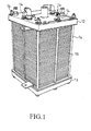
- a plurality of the above cell units are stacked and serially connected to provide sufficient power to construct a cell stack, as illustrated in Fig. 1.
- the cell stack 10 is positioned between two end plates 12, 13 provided at the longitudinal, opposing ends of the cell stack.
- a tightening device, such as a plurality of tie rods 14, passes through a peripheral region of each end plate 12, 13 for positioning the cell stack 10 between the two end plates 12, 13.
- the cell stack While performing the aforesaid reverse reaction of the electrolysis of water, in order to convert the chemical energy into electrical energy, the cell stack must be maintained under a consistent pressure range so as to ensure that the reverse reaction of the electrolysis of water is performed under the optimum pressure condition, so as to enhance the conversion efficiency of the chemical energy into electrical energy.
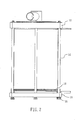
- Fig. 2 illustrates a conventional fuel cell, comprising the aforesaid fuel stack 10, two end plates, 12, 13, and a plurality of tie rods 14.
- a conventional fuel cell further includes a plurality of resilient members 50, such as springs, that are affixed between the lower end plate 13 and each of the tie rods 14. Adjustment can be made as to how tight each of the tie rods 14 should be affixed to the end plates, to such a degree that the rebounding force of each of the resilient member 50 being applied to the lower end plate 13 is approximately equal to the contact pressure required for optimizing the conductivity of each cell unit.
- the primary objective of this invention is to overcome the disadvantages of the conventional pressure-maintaining device and to provide a uniform compression device that is able to constantly apply a consistent pressure towards a cell stack. Further, such a uniform compression device can be adapted to adjust the pressure variation caused by thermal expansion, and to compensate for the height deviation resulting from stacking the cell units into a cell stack, thereby enhancing the operative efficiency of the fuel cell.
- the major technical content of this invention is to implement a metallic pressure bellows that is positioned between the cell stack and one of the end plates. Because the pressure bellows is made of metal materials, the tendency of pressure leakage is reduced. Further, the pressure bellows constantly applies pressure to the cell stack in a "planar" manner such that the complicated processes required adjusting the conventional pressure maintaining device can be eliminated. The pressure bellows further prevent the pressure being applied to the cell stack from varying with respect to the locations of the tie rods.
- the fuel cell comprises: a fuel cell stack 10; an upper end plate 12 and a lower end plate 13; a plurality of tie rods 14; and a uniform compression device 100.
- the end plates 12, 14 each have a central region and a peripheral region and are disposed at the longitudinal, opposing ends of the cell stack 10.
- the tie rods 14 pass through the peripheral region of the two end plates 12, 13 and position the cell stack 10 between the central regions of the two end plates 12, 13 by means of bolts 15.
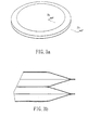
- Fig. 3a is a perspective view illustrating a uniform compression device 100 of this invention
- Fig. 3b is a cross-sectional view taken along lines 3b-3b of Fig. 3a, where the uniform compression device 100 comprises a pressure bellows made of a metallic material.
- the lower end plate 13 is preferred to be formed, at a side facing the cell stack 10, with a recess 132 adapted to receive the uniform compression device 100 therein.
- Fig. 5 is a cross-sectional, schematic view showing an alternative, preferred embodiment of this invention.
- the upper end plate 12 and the cell stack 10 are further provided with another pressure bellows therebetween.
- the upper end plate 13 is also, at a side facing the cell stack 10, with a recess 122 adapted to receive the uniform compression device 102 therein.
- the uniform compression devices 100, 102 of this invention are made of a metallic pressure bellows, the tendency of pressure leakage is reduced. Further, the pressure bellows constantly applies consistent and symmetrical pressure to the cell stack 10 in a "planar" manner, whereby such a uniform compression device can be adapted to adjust the pressure variation caused by thermal expansion, and to compensate the height deviation resulting from stacking the cell units into a cell stack, thereby enhancing the operative efficiency of the fuel cell.
Landscapes
- Life Sciences & Earth Sciences (AREA)
- Engineering & Computer Science (AREA)
- Manufacturing & Machinery (AREA)
- Sustainable Development (AREA)
- Sustainable Energy (AREA)
- Chemical & Material Sciences (AREA)
- Chemical Kinetics & Catalysis (AREA)
- Electrochemistry (AREA)
- General Chemical & Material Sciences (AREA)
- Fuel Cell (AREA)
Applications Claiming Priority (2)
| Application Number | Priority Date | Filing Date | Title |
|---|---|---|---|
| CNB011242221A CN1295806C (zh) | 2001-08-16 | 2001-08-16 | 具有均布压力装置的燃料电池 |
| CN01124222 | 2001-08-16 |
Publications (2)
| Publication Number | Publication Date |
|---|---|
| EP1284521A2 true EP1284521A2 (fr) | 2003-02-19 |
| EP1284521A3 EP1284521A3 (fr) | 2005-12-07 |
Family
ID=4665590
Family Applications (1)
| Application Number | Title | Priority Date | Filing Date |
|---|---|---|---|
| EP02003460A Withdrawn EP1284521A3 (fr) | 2001-08-16 | 2002-02-14 | Pile à combustible avec dispositif de compression uniforme |
Country Status (2)
| Country | Link |
|---|---|
| EP (1) | EP1284521A3 (fr) |
| CN (1) | CN1295806C (fr) |
Cited By (10)
| Publication number | Priority date | Publication date | Assignee | Title |
|---|---|---|---|---|
| WO2003028141A3 (fr) * | 2001-09-26 | 2004-02-26 | Global Thermoelectric Inc | Soufflet de compression destine a une pile a combustible oxyde solide |
| WO2004066414A3 (fr) * | 2003-01-21 | 2004-10-21 | Gen Motors Corp | Jonction de plaques bipolaires dans des empilages de piles a combustible a membrane echangeuse de protons |
| DE10343766A1 (de) * | 2003-09-16 | 2005-06-02 | Stefan Dr. Nettesheim | Spannvorrichtung für einen Stapel aus einer Mehrzahl elektrochemischer Zellen und Verfahren zu deren Montage |
| WO2006075050A1 (fr) * | 2005-01-13 | 2006-07-20 | Wärtsilä Finland Oy | Dispositif pour comprimer des piles a combustible dans un assemblage de piles a combustible |
| EP1816698A1 (fr) * | 2006-01-23 | 2007-08-08 | Asia Pacific Fuel Cell Technologies, Ltd. | Appareil d'ajustement de pression pour une unité de pile à combustible |
| DE102011077061A1 (de) * | 2011-06-07 | 2012-12-13 | Siemens Aktiengesellschaft | Energiewandlungseinheit zur elektrochemischen Energiewandlung und Verfahren unter deren Verwendung |
| US8455155B2 (en) | 2006-11-22 | 2013-06-04 | GM Global Technology Operations LLC | Inexpensive approach for coating bipolar plates for PEM fuel cells |
| EP2595231B1 (fr) * | 2011-11-21 | 2017-07-26 | Delphi Technologies, Inc. | Ensemble empilement de piles à combustible avec mécanisme de charge équilibrée en pression et procédé d'assemblage |
| CN115516675A (zh) * | 2020-07-23 | 2022-12-23 | Avl李斯特有限公司 | 用于燃料电池堆的可移除的负荷传感器 |
| WO2026082306A1 (fr) * | 2024-10-18 | 2026-04-23 | Siemens Energy Global GmbH & Co. KG | Module de pile à combustible, système et procédé |
Families Citing this family (2)
| Publication number | Priority date | Publication date | Assignee | Title |
|---|---|---|---|---|
| CN101577336B (zh) * | 2008-05-07 | 2012-09-19 | 财团法人工业技术研究院 | 用于电池系统的端板及使用此端板的电池系统 |
| CN107293772B (zh) * | 2016-03-31 | 2019-09-17 | 清华大学 | 燃料电池 |
Family Cites Families (7)
| Publication number | Priority date | Publication date | Assignee | Title |
|---|---|---|---|---|
| JP2500880B2 (ja) * | 1991-08-30 | 1996-05-29 | 株式会社日立製作所 | 燃料電池 |
| US5252410A (en) * | 1991-09-13 | 1993-10-12 | Ballard Power Systems Inc. | Lightweight fuel cell membrane electrode assembly with integral reactant flow passages |
| US5264300A (en) * | 1992-01-09 | 1993-11-23 | Gebrueder Sulzer Aktiengesellschaft | Centrally symmetrical fuel cell battery |
| CN2329088Y (zh) * | 1997-11-24 | 1999-07-14 | 钟家轮 | 质子交换膜燃料电池 |
| JP2000100457A (ja) * | 1998-09-25 | 2000-04-07 | Matsushita Electric Ind Co Ltd | 燃料電池 |
| DE19852363C1 (de) * | 1998-11-13 | 2000-05-18 | Mtu Friedrichshafen Gmbh | Brennstoffzellenanordnung |
| US6200698B1 (en) * | 1999-08-11 | 2001-03-13 | Plug Power Inc. | End plate assembly having a two-phase fluid-filled bladder and method for compressing a fuel cell stack |
-
2001
- 2001-08-16 CN CNB011242221A patent/CN1295806C/zh not_active Expired - Fee Related
-
2002
- 2002-02-14 EP EP02003460A patent/EP1284521A3/fr not_active Withdrawn
Cited By (11)
| Publication number | Priority date | Publication date | Assignee | Title |
|---|---|---|---|---|
| WO2003028141A3 (fr) * | 2001-09-26 | 2004-02-26 | Global Thermoelectric Inc | Soufflet de compression destine a une pile a combustible oxyde solide |
| WO2004066414A3 (fr) * | 2003-01-21 | 2004-10-21 | Gen Motors Corp | Jonction de plaques bipolaires dans des empilages de piles a combustible a membrane echangeuse de protons |
| US6887610B2 (en) * | 2003-01-21 | 2005-05-03 | General Motors Corporation | Joining of bipolar plates in proton exchange membrane fuel cell stacks |
| DE10343766A1 (de) * | 2003-09-16 | 2005-06-02 | Stefan Dr. Nettesheim | Spannvorrichtung für einen Stapel aus einer Mehrzahl elektrochemischer Zellen und Verfahren zu deren Montage |
| WO2006075050A1 (fr) * | 2005-01-13 | 2006-07-20 | Wärtsilä Finland Oy | Dispositif pour comprimer des piles a combustible dans un assemblage de piles a combustible |
| EP1816698A1 (fr) * | 2006-01-23 | 2007-08-08 | Asia Pacific Fuel Cell Technologies, Ltd. | Appareil d'ajustement de pression pour une unité de pile à combustible |
| US8455155B2 (en) | 2006-11-22 | 2013-06-04 | GM Global Technology Operations LLC | Inexpensive approach for coating bipolar plates for PEM fuel cells |
| DE102011077061A1 (de) * | 2011-06-07 | 2012-12-13 | Siemens Aktiengesellschaft | Energiewandlungseinheit zur elektrochemischen Energiewandlung und Verfahren unter deren Verwendung |
| EP2595231B1 (fr) * | 2011-11-21 | 2017-07-26 | Delphi Technologies, Inc. | Ensemble empilement de piles à combustible avec mécanisme de charge équilibrée en pression et procédé d'assemblage |
| CN115516675A (zh) * | 2020-07-23 | 2022-12-23 | Avl李斯特有限公司 | 用于燃料电池堆的可移除的负荷传感器 |
| WO2026082306A1 (fr) * | 2024-10-18 | 2026-04-23 | Siemens Energy Global GmbH & Co. KG | Module de pile à combustible, système et procédé |
Also Published As
| Publication number | Publication date |
|---|---|
| CN1295806C (zh) | 2007-01-17 |
| CN1405913A (zh) | 2003-03-26 |
| EP1284521A3 (fr) | 2005-12-07 |
Similar Documents
| Publication | Publication Date | Title |
|---|---|---|
| US6689503B2 (en) | Fuel cell with uniform compression device | |
| EP0798800B1 (fr) | Pile à combustible à carbonates fondus et système de production d'énergie la contenant | |
| RU2431220C2 (ru) | Узел сжатия для распределения наружного усилия сжатия к стопке твердооксидных топливных элементов и стопка твердооксидных топливных элементов | |
| US7390586B2 (en) | Fuel cell stacks of alternating polarity membrane electrode assemblies | |
| JP3736765B2 (ja) | 燃料電池スタックのマニホールド保持システム | |
| EP1284521A2 (fr) | Pile à combustible avec dispositif de compression uniforme | |
| US20050064268A1 (en) | Fastening mechanism of a fuel cell stack | |
| US6677071B2 (en) | Bipolar plate for a fuel cell | |
| EP1235289A3 (fr) | Plaque bipolaire estampée pour empilement de piles à combustible de type PEM | |
| US9023546B2 (en) | Fuel cell | |
| CN109830732B (zh) | 一种不对称平板型结构高温固态燃料电池的电堆结构 | |
| KR100488875B1 (ko) | 연료전지 스택의 체결 구조 | |
| CA2613652A1 (fr) | Empilement de cellules electrochimiques | |
| EP1284512A2 (fr) | Plaque bipolaire pour une pile à combustible | |
| JP2005141935A (ja) | 燃料電池スタック | |
| KR101353839B1 (ko) | 우수한 면압 균일성 및 내구성을 갖는 고체산화물 연료전지 | |
| KR20050039354A (ko) | 연료전지 스택 체결장치 | |
| KR20050045070A (ko) | 연료전지 스택 체결장치 | |
| KR100783842B1 (ko) | 연료전지 스택의 체결 구조 | |
| CN113937327B (zh) | 膜电极组件、燃料电池单体、燃料电池和车辆 | |
| JPH06275307A (ja) | 燃料電池 | |
| JP4447133B2 (ja) | 燃料電池 | |
| KR102346856B1 (ko) | 출력 밀도 향상 및 적층이 용이한 흐름식 에너지 저장장치 셀스택의 체결구조 및 이를 적용한 흐름식 에너지 저장장치 | |
| JPS5975576A (ja) | 燃料電池 | |
| US9406953B2 (en) | Fuel cell stack |
Legal Events
| Date | Code | Title | Description |
|---|---|---|---|
| PUAI | Public reference made under article 153(3) epc to a published international application that has entered the european phase |
Free format text: ORIGINAL CODE: 0009012 |
|
| AK | Designated contracting states |
Designated state(s): AT BE CH CY DE DK ES FI FR GB GR IE IT LI LU MC NL PT SE TR |
|
| AX | Request for extension of the european patent |
Extension state: AL LT LV MK RO SI |
|
| PUAL | Search report despatched |
Free format text: ORIGINAL CODE: 0009013 |
|
| AK | Designated contracting states |
Kind code of ref document: A3 Designated state(s): AT BE CH CY DE DK ES FI FR GB GR IE IT LI LU MC NL PT SE TR |
|
| AX | Request for extension of the european patent |
Extension state: AL LT LV MK RO SI |
|
| 17P | Request for examination filed |
Effective date: 20060407 |
|
| 17Q | First examination report despatched |
Effective date: 20060706 |
|
| AKX | Designation fees paid |
Designated state(s): AT BE CH CY DE DK ES FI FR GB GR IE IT LI LU MC NL PT SE TR |
|
| STAA | Information on the status of an ep patent application or granted ep patent |
Free format text: STATUS: THE APPLICATION IS DEEMED TO BE WITHDRAWN |
|
| 18D | Application deemed to be withdrawn |
Effective date: 20070117 |