EP1284533B1 - Verdrahtungskanal - Google Patents
Verdrahtungskanal Download PDFInfo
- Publication number
- EP1284533B1 EP1284533B1 EP02012654A EP02012654A EP1284533B1 EP 1284533 B1 EP1284533 B1 EP 1284533B1 EP 02012654 A EP02012654 A EP 02012654A EP 02012654 A EP02012654 A EP 02012654A EP 1284533 B1 EP1284533 B1 EP 1284533B1
- Authority
- EP
- European Patent Office
- Prior art keywords
- side walls
- base
- tongues
- feature
- wiring conduit
- Prior art date
- Legal status (The legal status is an assumption and is not a legal conclusion. Google has not performed a legal analysis and makes no representation as to the accuracy of the status listed.)
- Expired - Lifetime
Links
- 210000002105 tongue Anatomy 0.000 claims description 15
- 229920002994 synthetic fiber Polymers 0.000 claims 1
- 229920001169 thermoplastic Polymers 0.000 claims 1
- 239000004416 thermosoftening plastic Substances 0.000 claims 1
- 238000009429 electrical wiring Methods 0.000 abstract 1
- 238000003780 insertion Methods 0.000 description 3
- 230000037431 insertion Effects 0.000 description 3
- 238000005192 partition Methods 0.000 description 3
- 230000003014 reinforcing effect Effects 0.000 description 1
- 239000012815 thermoplastic material Substances 0.000 description 1
- 230000003313 weakening effect Effects 0.000 description 1
Images
Classifications
-
- H—ELECTRICITY
- H02—GENERATION; CONVERSION OR DISTRIBUTION OF ELECTRIC POWER
- H02G—INSTALLATION OF ELECTRIC CABLES OR LINES, OR OF COMBINED OPTICAL AND ELECTRIC CABLES OR LINES
- H02G3/00—Installations of electric cables or lines or protective tubing therefor in or on buildings, equivalent structures or vehicles
- H02G3/02—Details
- H02G3/04—Protective tubing or conduits, e.g. cable ladders or cable troughs
- H02G3/0437—Channels
- H02G3/045—Channels provided with perforations or slots permitting introduction or exit of wires
Definitions
- the invention relates to wiring channels according to the preamble of claim 1.
- Wiring channels have been known and used for many decades in a wide variety of variants. For example, compare US 2,896,009 , registered in 1955, US 2,921,607 . FR 1 213 786 . FR 11 77 110 . FR 1 224 204 . DE 1 829 069U . DE-AS 1 440 231 . DE-AS 1 440 237 . DE 1 848 965U . DE 2 002 912A . DE 27 14 885C . DE 30 14 695A . EP 0315 531B . FR 2 691 227A .
- EP 0 570 272B and DE 198 28 082A All these wiring channels have a bottom, two side walls that are formed into tongues by slots extending perpendicular to the bottom, cover retaining profiles on the free longitudinal edges of the side walls, and optionally a cover that can be releasably attached to the cover retaining profiles of the side walls.
- Wiring channels are mainly used in control cabinets, where they allow the proper laying of wires and lines.
- the slots in the side walls have the task to allow the insertion and removal of wires and wires.
- tongues are in the DE-AS 14 40 231 and the DE-AS 14 40 237 Wiring channels provided with predetermined breaking points, which should allow the clean breaking of the tongues without the aid of a tool.
- the wiring channels are closed with a lid, special attention must be given to the shape of the lid holding profiles. Due to the regularly introduced slots, the stability of the side walls is already reduced. About that In addition, in cabinets with elevated temperatures can be expected, resulting in a further reduction in the elasticity of the tongues. In order to prevent even under unfavorable circumstances, an automatic release of the lid, the tongues, the lid holding profiles and the lid are dimensioned so that the profiles overlap each other over a wide area and receive the tongues with the lid a large bias. As a result, however, the placement and removal of the lid is made more difficult and in particular the space available for receiving wires and lines available interior of the wiring channels is reduced.
- the present invention is therefore the object of developing a wiring channel of the type mentioned in such a way that for the insertion and removal of cables and wires optimal space is available, at the same time the possibility is created to use additional elements such as partitions and the like ,
- predetermined breaking points can be formed as known per se, but now in the bottom area.
- the channel according to the invention can also be made of a thermoplastic material.
- the floor reinforcing longitudinal strip is formed as a retaining strip, can be snapped onto the additional parts such as partitions and the like.
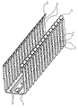
- the drawing shows an isometric view of a wiring channel with a U-shaped cross-section. He has a bottom 1, two side walls, which are formed by regularly incorporated, running perpendicular to the bottom slots 2 to tongues 3, and cover retaining profiles 4 at the free longitudinal edges of the side walls or tongues 3.
- the slots 2 are beyond the side walls to in extends the bottom 1 inside. If a tongue 3 is broken off to allow the insertion or removal of cables with a large cross-section, so it breaks in the bottom area and there is a floor-level cable outlet with a maximum large cross-section.
- the breaking point can be defined defined by an incorporated predetermined breaking line.
- two parallel longitudinal strips 5 are mounted on the inside. These are shaped so that they can serve as retaining strips on which additional parts such as partitions or the like can be snapped.
Landscapes
- Engineering & Computer Science (AREA)
- Architecture (AREA)
- Civil Engineering (AREA)
- Structural Engineering (AREA)
- Installation Of Indoor Wiring (AREA)
- Details Of Indoor Wiring (AREA)
- Internal Circuitry In Semiconductor Integrated Circuit Devices (AREA)
- Television Systems (AREA)
- Optical Communication System (AREA)
- Multi-Conductor Connections (AREA)
Description
- Die Erfindung betrifft Verdrahtungskanäle gemäß dem Oberbegriff des Anspruchs 1.
- Verdrahtungskanäle sind seit vielen Jahrzehnten in den unterschiedlichsten Varianten bekannt und in Gebrauch. Man vergleiche beispielsweise
US 2 896 009 , angemeldet 1955,US 2 921 607 ,FR 1 213 786 FR 11 77 110 FR 1 224 204 DE 1 829 069U ,DE-AS 1 440 231 ,DE-AS 1 440 237 ,DE 1 848 965U ,DE 2 002 912A ,DE 27 14 885C ,DE 30 14 695A ,EP 0315 531B ,FR 2 691 227A EP 0 570 272B undDE 198 28 082A , angemeldet 1998. Alle diese Verdrahtungskanäle besitzen einen Boden, zwei Seitenwände, die durch senkrecht zum Boden verlaufende Schlitze zu Zungen umgeformt sind, Deckelhalteprofile an den freien Längskanten der Seitenwände und gegebenenfalls einen Deckel, der auf die Deckelhalteprofile der Seitenwände lösbar aufgesetzt werden kann. - Verdrahtungskanäle werden überwiegend in Schaltschränken eingesetzt, wo sie die ordentliche Verlegung von Drähten und Leitungen ermöglichen. Dabei haben die Schlitze in den Seitenwänden die Aufgabe, das Ein- und Ausführen von Drähten und Leitungen zu ermöglichen.
- Falls Kabel ein- oder ausgeführt werden müssen, die einen größeren Querschnitt haben als die Schlitzbreite, können einzelne Zungen abgebrochen werden. Um dieses Abbrechen zu erleichtern, sind die Zungen der in der
DE-AS 14 40 231 und derDE-AS 14 40 237 offenbarten Verdrahtungskanäle mit Sollbruchstellen versehen, die das saubere Abbrechen der Zungen auch ohne Zuhilfenahme eines Werkzeugs ermöglichen sollen. - Analysiert man die in den oben genannten Druckschriften offenbarten Verdrahtungskanäle, so stellt man fest, dass die in die Seitenwände eingearbeiteten Schlitze ausnahmslos ein gutes Stück oberhalb des Bodens enden. Beim Abbrechen einer Zunge bleibt somit ein oftmals störendes Stück Seitenwand stehen.
- Falls die Verdrahtungskanäle mit einem Deckel verschlossen werden, muss der Form der Deckelhalteprofile besondere Aufmerksamkeit geschenkt werden. Durch die regelmäßig eingebrachten Schlitze ist die Stabilität der Seitenwände bereits reduziert. Darüber hinaus muss in Schaltschränken mit erhöhten Temperaturen gerechnet werden, was zu einer weiteren Verringerung der Elastizität der Zungen führt. Um auch unter ungünstigen Umständen ein selbsttätiges Lösen des Deckels zu verhindern, werden die Zungen, die Deckelhalteprofile und der Deckel so dimensioniert, dass die Profile sich breitflächig überlappen und die Zungen bei aufgesetztem Deckel eine große Vorspannung erhalten. Dadurch wird jedoch das Aufsetzen und Abnehmen des Deckels erschwert und insbesondere der für die Aufnahme von Drähten und Leitungen zur Verfügung stehende Innenraum der Verdrahtungskanäle verringert.
- Der vorliegenden Erfindung liegt daher die Aufgabe zugrunde, einen Verdrahtungskanal der eingangs genannten Art derart weiterzubilden, dass für das Ein- und Ausführen von Kabeln und Drähten ein optimales Platzangebot zur Verfügung steht, wobei gleichzeitig die Möglichkeit geschaffen wird, Zusatzelemente wie Trennwände und dergleichen zu verwenden.
- Diese Aufgabe wird gelöst durch einen Verdrahtungskanal mit den Merkmalen des Anspruchs 1.
- Durch das Verlängern der Schlitze in den Seitenwänden bis in den Bodenbereich können Kabel und Drähte nunmehr über die volle Höhe der Seitenwand ein- und ausgeführt werden. Beim Abbrechen einer Zunge ergibt sich eine Öffnung, die bodengleich ist. Die durch die Verlängerung der Schlitze bis in den Bodenbereich hinein erfolgte Schwächung der Festigkeit des Bodens wird durch die mindestens eine Längsleiste mehr als ausgeglichen, insbesondere dadurch, dass diese wenigstens eine Längsleiste, wobei es sich gemäß einer bevorzugten Weiterbildung um zwei parallele Längsleisten handelt.
- Um eine definierte Bruchstelle zum Abbrechen der Zungen zu schaffen, können wie an sich bekannt Sollbruchstellen angeformt werden, jetzt jedoch im Bodenbereich.
- Wie an sich bekannt, kann auch der erfindungsgemäße Kanal aus einem thermoplastischen Kunststoff hergestellt sein.
- Vorteilhafterweise ist die den Boden verstärkende Längsleiste als Halteleiste ausgebildet, auf die Zusatzteile wie Trennwände und dergleichen aufgerastet werden können.
- Anhand der Zeichnung soll die Erfindung in Form von Ausführungsbeispielen näher erläutert werden.
- Die Zeichnung zeigt in isometrischer Darstellung einen Verdrahtungskanal mit U-förmigem Querschnitt. Er besitzt einen Boden 1, zwei Seitenwände, die durch regelmäßig eingearbeitete, senkrecht zum Boden verlaufende Schlitze 2 zu Zungen 3 umgeformt sind, und Deckelhalteprofile 4 an den freien Längskanten der Seitenwände bzw. Zungen 3. Die Schlitze 2 sind über die Seitenwände hinaus bis in den Boden 1 hinein verlängert. Wird eine Zunge 3 abgebrochen, um das Ein- oder Ausführen von Kabeln mit großem Querschnitt zu ermöglichen, so bricht sie im Bodenbereich und es entsteht eine bodengleiche Kabelauslassöffnung mit maximal großem Querschnitt. Gegebenenfalls kann die Bruchstelle durch eine eingearbeitete Sollbruchlinie definiert vorgegeben werden.
- Um die aufgrund der Schlitze 2 verringerte Stabilität des Bodens 1 wieder herzustellen, sind auf dessen Innenseite zwei parallele Längsleisten 5 angebracht. Diese sind so geformt, dass sie als Halteleisten dienen können, auf die Zusatzteile wie Trennwände oder dergleichen aufgerastet werden können.
Claims (5)
- Verdrahtungskanal, im wesentlichen umfassend- einen Boden (1),- Seitenwände, die durch senkrecht zum Boden (1) verlaufende Schlitze (2) zu Zungen (3) umgeformt sind,- Deckelhalteprofile (4) an den Seitenwänden- und gegebenenfalls einen Deckel (10), lösbar aufzusetzen auf die Seitenwände, gekennzeichnet durch die Merkmale:- die Schlitze (2) sind über die Seitenwände hinaus bis in den Boden (1) verlängert,- der Boden (1) ist durch wenigstens eine Längsleiste (5) verstärkt.
- Verdrahtungskanal nach Anspruch 1, gekennzeichnet durch das Merkmal:- es sind zwei parallele Längsleisten (5) vorgesehen.
- Verdrahtungskanal nach Anspruch 1 oder 2, gekennzeichnet durch das Merkmal:- die Zungen (3) besitzen im Bodenbereich angeformte Sollbruchstellen.
- Verdrahtungskanal nach Anspruch 1, 2 oder 3, gekennzeichnet durch das Merkmal:- Kanal (1, 3, 4, 5), Deckel (10) und/oder Halter (20) bestehen aus thermoplastischem Kunststoff.
- Verdrahtungskanal nach einem der Ansprüche 1 bis 4, gekennzeichnet durch das Merkmal :- die Längsleiste (5) ist als Halteleiste für die lösbare Befestigung von Zusatzteilen (20) wie Trennwänden oder dergleichen ausgebildet.
Applications Claiming Priority (2)
| Application Number | Priority Date | Filing Date | Title |
|---|---|---|---|
| DE20113694U | 2001-08-18 | ||
| DE20113694U DE20113694U1 (de) | 2001-08-18 | 2001-08-18 | Verdrahtungskanal |
Publications (2)
| Publication Number | Publication Date |
|---|---|
| EP1284533A1 EP1284533A1 (de) | 2003-02-19 |
| EP1284533B1 true EP1284533B1 (de) | 2010-03-17 |
Family
ID=7960664
Family Applications (1)
| Application Number | Title | Priority Date | Filing Date |
|---|---|---|---|
| EP02012654A Expired - Lifetime EP1284533B1 (de) | 2001-08-18 | 2002-06-07 | Verdrahtungskanal |
Country Status (6)
| Country | Link |
|---|---|
| EP (1) | EP1284533B1 (de) |
| AT (1) | ATE461545T1 (de) |
| DE (2) | DE20113694U1 (de) |
| DK (1) | DK1284533T3 (de) |
| ES (1) | ES2342923T3 (de) |
| PT (1) | PT1284533E (de) |
Families Citing this family (2)
| Publication number | Priority date | Publication date | Assignee | Title |
|---|---|---|---|---|
| DE202008005430U1 (de) | 2008-04-19 | 2009-08-27 | Tehalit Gmbh | Verdrahtungskanal mit Anti-Rutsch-Funktion |
| DE102021133811B4 (de) | 2021-12-20 | 2024-04-25 | Rittal Gmbh & Co. Kg | Kabelkanal für automatisierte Verdrahtung einer elektrischen Steuerungs- oder Schaltanlage |
Family Cites Families (4)
| Publication number | Priority date | Publication date | Assignee | Title |
|---|---|---|---|---|
| DE1851657U (de) * | 1961-02-03 | 1962-05-17 | Josef Eisert | Drahtkanal fuer elektrische schaltanordnungen. |
| DE1440231B2 (de) * | 1961-04-29 | 1970-05-27 | Theysohn, Albert, 6751 Heltersberg | Kabelfuhrungskanal |
| US3321571A (en) * | 1965-02-02 | 1967-05-23 | Republic Ind Corp | Flexible conduit |
| DE19828082A1 (de) * | 1998-06-24 | 1999-12-30 | Bettermann Obo Gmbh & Co Kg | Verdrahtungskanal aus Kunststoff |
-
2001
- 2001-08-18 DE DE20113694U patent/DE20113694U1/de not_active Expired - Lifetime
-
2002
- 2002-06-07 EP EP02012654A patent/EP1284533B1/de not_active Expired - Lifetime
- 2002-06-07 ES ES02012654T patent/ES2342923T3/es not_active Expired - Lifetime
- 2002-06-07 AT AT02012654T patent/ATE461545T1/de active
- 2002-06-07 DK DK02012654.6T patent/DK1284533T3/da active
- 2002-06-07 PT PT02012654T patent/PT1284533E/pt unknown
- 2002-06-07 DE DE50214281T patent/DE50214281D1/de not_active Expired - Lifetime
Also Published As
| Publication number | Publication date |
|---|---|
| PT1284533E (pt) | 2010-06-02 |
| DK1284533T3 (da) | 2010-06-14 |
| ATE461545T1 (de) | 2010-04-15 |
| DE20113694U1 (de) | 2003-01-09 |
| DE50214281D1 (de) | 2010-04-29 |
| EP1284533A1 (de) | 2003-02-19 |
| ES2342923T3 (es) | 2010-07-19 |
Similar Documents
| Publication | Publication Date | Title |
|---|---|---|
| DE69002960T2 (de) | Profileisen, wie Rinne, Fussleiste, Wandleiste oder dergleichen, als Gehäuse und zum Schützen von elektrischen Geräten und Kabeln für ihre Versorgung. | |
| EP2631414A2 (de) | Führungsschiene für Senkrechtmarkise und Senkrechtmarkise | |
| EP3568610A1 (de) | Trennsteg für energieführungsketten | |
| DE102016124609A1 (de) | Verteilerkasten zum Einbau in eine Wandöffnung | |
| DE69004380T2 (de) | Klammerartige Abdeckungsverbindung für eine Leiste oder Rinne. | |
| DE20113696U1 (de) | Installationskanal | |
| EP1284533A1 (de) | Verdrahtungskanal | |
| DE69706627T2 (de) | Halteklammer für Kabelrinnen und zugehörige Kabelrinne | |
| EP1294065B1 (de) | Verdrahtungskanal | |
| DE7711728U1 (de) | Kabelinstallationskanal | |
| DE4308566A1 (de) | Wandinstallationskanal | |
| DE202009009353U1 (de) | Geräteträger für Sockelleistenkanäle | |
| DE68901809T2 (de) | Einsatz fuer u-profile. | |
| DE602004001437T2 (de) | Montagekonsole für Kabelkanäle | |
| DE202007010127U1 (de) | Überbrückungsklammer zur Sicherung von Kabeln und Leitungen in Kabelführungskanälen | |
| DE102004013010B3 (de) | Vorrichtung zur Aufnahme von länglichen Gegenständen | |
| DE2804419A1 (de) | Installationskanal | |
| DE10306860B4 (de) | Kettenglied für eine Energieführungskette | |
| EP2086078A2 (de) | Verteilerkasten zum Einbau in eine Wandöffnung | |
| CH669223A5 (de) | Webmaschine und verfahren zur herstellung der webmaschine. | |
| EP1830011B1 (de) | Bewehrungshalter | |
| DE3215943C2 (de) | Führungsschiene für Vertikal-Jalousien | |
| EP1376797B1 (de) | Verdrahtungskanal | |
| DE202008005430U1 (de) | Verdrahtungskanal mit Anti-Rutsch-Funktion | |
| DE102004048055A1 (de) | Kabeleinführungsvorrichtung für eine Gehäusewand |
Legal Events
| Date | Code | Title | Description |
|---|---|---|---|
| PUAI | Public reference made under article 153(3) epc to a published international application that has entered the european phase |
Free format text: ORIGINAL CODE: 0009012 |
|
| AK | Designated contracting states |
Designated state(s): AT BE CH CY DE DK ES FI FR GB GR IE IT LI LU MC NL PT SE TR |
|
| AX | Request for extension of the european patent |
Extension state: AL LT LV MK RO SI |
|
| 17P | Request for examination filed |
Effective date: 20030326 |
|
| AKX | Designation fees paid |
Designated state(s): AT BE CH CY DE DK ES FI FR GB GR IE IT LI LU MC NL PT SE TR |
|
| RAP1 | Party data changed (applicant data changed or rights of an application transferred) |
Owner name: TEHALIT GMBH |
|
| RAP1 | Party data changed (applicant data changed or rights of an application transferred) |
Owner name: TEHALIT GMBH |
|
| 17Q | First examination report despatched |
Effective date: 20060606 |
|
| GRAP | Despatch of communication of intention to grant a patent |
Free format text: ORIGINAL CODE: EPIDOSNIGR1 |
|
| GRAS | Grant fee paid |
Free format text: ORIGINAL CODE: EPIDOSNIGR3 |
|
| GRAA | (expected) grant |
Free format text: ORIGINAL CODE: 0009210 |
|
| AK | Designated contracting states |
Kind code of ref document: B1 Designated state(s): AT BE CH CY DE DK ES FI FR GB GR IE IT LI LU MC NL PT SE TR |
|
| REG | Reference to a national code |
Ref country code: GB Ref legal event code: FG4D Free format text: NOT ENGLISH |
|
| REG | Reference to a national code |
Ref country code: CH Ref legal event code: EP |
|
| REG | Reference to a national code |
Ref country code: IE Ref legal event code: FG4D |
|
| REF | Corresponds to: |
Ref document number: 50214281 Country of ref document: DE Date of ref document: 20100429 Kind code of ref document: P |
|
| REG | Reference to a national code |
Ref country code: PT Ref legal event code: SC4A Free format text: AVAILABILITY OF NATIONAL TRANSLATION Effective date: 20100526 |
|
| REG | Reference to a national code |
Ref country code: NL Ref legal event code: T3 |
|
| REG | Reference to a national code |
Ref country code: DK Ref legal event code: T3 |
|
| REG | Reference to a national code |
Ref country code: CH Ref legal event code: NV Representative=s name: PATENTANWAELTE SCHAAD, BALASS, MENZL & PARTNER AG |
|
| REG | Reference to a national code |
Ref country code: SE Ref legal event code: TRGR |
|
| REG | Reference to a national code |
Ref country code: ES Ref legal event code: FG2A Ref document number: 2342923 Country of ref document: ES Kind code of ref document: T3 |
|
| REG | Reference to a national code |
Ref country code: GR Ref legal event code: EP Ref document number: 20100401354 Country of ref document: GR |
|
| PG25 | Lapsed in a contracting state [announced via postgrant information from national office to epo] |
Ref country code: CY Free format text: LAPSE BECAUSE OF FAILURE TO SUBMIT A TRANSLATION OF THE DESCRIPTION OR TO PAY THE FEE WITHIN THE PRESCRIBED TIME-LIMIT Effective date: 20100317 |
|
| PLBE | No opposition filed within time limit |
Free format text: ORIGINAL CODE: 0009261 |
|
| STAA | Information on the status of an ep patent application or granted ep patent |
Free format text: STATUS: NO OPPOSITION FILED WITHIN TIME LIMIT |
|
| PG25 | Lapsed in a contracting state [announced via postgrant information from national office to epo] |
Ref country code: MC Free format text: LAPSE BECAUSE OF NON-PAYMENT OF DUE FEES Effective date: 20100630 |
|
| 26N | No opposition filed |
Effective date: 20101220 |
|
| PGFP | Annual fee paid to national office [announced via postgrant information from national office to epo] |
Ref country code: LU Payment date: 20110622 Year of fee payment: 10 |
|
| PGFP | Annual fee paid to national office [announced via postgrant information from national office to epo] |
Ref country code: IE Payment date: 20120619 Year of fee payment: 11 Ref country code: CH Payment date: 20120622 Year of fee payment: 11 Ref country code: DK Payment date: 20120625 Year of fee payment: 11 Ref country code: DE Payment date: 20120524 Year of fee payment: 11 Ref country code: NL Payment date: 20120628 Year of fee payment: 11 |
|
| PGFP | Annual fee paid to national office [announced via postgrant information from national office to epo] |
Ref country code: SE Payment date: 20120625 Year of fee payment: 11 Ref country code: GB Payment date: 20120621 Year of fee payment: 11 Ref country code: GR Payment date: 20120628 Year of fee payment: 11 Ref country code: FR Payment date: 20120705 Year of fee payment: 11 Ref country code: FI Payment date: 20120620 Year of fee payment: 11 |
|
| REG | Reference to a national code |
Ref country code: DE Ref legal event code: R082 Ref document number: 50214281 Country of ref document: DE |
|
| PGFP | Annual fee paid to national office [announced via postgrant information from national office to epo] |
Ref country code: IT Payment date: 20120626 Year of fee payment: 11 |
|
| PG25 | Lapsed in a contracting state [announced via postgrant information from national office to epo] |
Ref country code: TR Free format text: LAPSE BECAUSE OF FAILURE TO SUBMIT A TRANSLATION OF THE DESCRIPTION OR TO PAY THE FEE WITHIN THE PRESCRIBED TIME-LIMIT Effective date: 20100317 |
|
| PGFP | Annual fee paid to national office [announced via postgrant information from national office to epo] |
Ref country code: BE Payment date: 20120622 Year of fee payment: 11 |
|
| PGFP | Annual fee paid to national office [announced via postgrant information from national office to epo] |
Ref country code: ES Payment date: 20120628 Year of fee payment: 11 |
|
| PGFP | Annual fee paid to national office [announced via postgrant information from national office to epo] |
Ref country code: PT Payment date: 20120531 Year of fee payment: 11 |
|
| PGFP | Annual fee paid to national office [announced via postgrant information from national office to epo] |
Ref country code: AT Payment date: 20120620 Year of fee payment: 11 |
|
| REG | Reference to a national code |
Ref country code: PT Ref legal event code: MM4A Free format text: LAPSE DUE TO NON-PAYMENT OF FEES Effective date: 20131209 |
|
| BERE | Be: lapsed |
Owner name: TEHALIT G.M.B.H. Effective date: 20130630 |
|
| REG | Reference to a national code |
Ref country code: NL Ref legal event code: V1 Effective date: 20140101 |
|
| PG25 | Lapsed in a contracting state [announced via postgrant information from national office to epo] |
Ref country code: SE Free format text: LAPSE BECAUSE OF NON-PAYMENT OF DUE FEES Effective date: 20130608 Ref country code: PT Free format text: LAPSE BECAUSE OF NON-PAYMENT OF DUE FEES Effective date: 20131209 |
|
| REG | Reference to a national code |
Ref country code: CH Ref legal event code: PL |
|
| REG | Reference to a national code |
Ref country code: SE Ref legal event code: EUG |
|
| REG | Reference to a national code |
Ref country code: DK Ref legal event code: EBP Effective date: 20130630 |
|
| REG | Reference to a national code |
Ref country code: AT Ref legal event code: MM01 Ref document number: 461545 Country of ref document: AT Kind code of ref document: T Effective date: 20130607 |
|
| GBPC | Gb: european patent ceased through non-payment of renewal fee |
Effective date: 20130607 |
|
| REG | Reference to a national code |
Ref country code: GR Ref legal event code: ML Ref document number: 20100401354 Country of ref document: GR Effective date: 20140103 |
|
| PG25 | Lapsed in a contracting state [announced via postgrant information from national office to epo] |
Ref country code: FI Free format text: LAPSE BECAUSE OF NON-PAYMENT OF DUE FEES Effective date: 20130607 |
|
| REG | Reference to a national code |
Ref country code: IE Ref legal event code: MM4A |
|
| REG | Reference to a national code |
Ref country code: FR Ref legal event code: ST Effective date: 20140228 |
|
| PG25 | Lapsed in a contracting state [announced via postgrant information from national office to epo] |
Ref country code: BE Free format text: LAPSE BECAUSE OF NON-PAYMENT OF DUE FEES Effective date: 20130630 |
|
| REG | Reference to a national code |
Ref country code: DE Ref legal event code: R119 Ref document number: 50214281 Country of ref document: DE Effective date: 20140101 |
|
| PG25 | Lapsed in a contracting state [announced via postgrant information from national office to epo] |
Ref country code: NL Free format text: LAPSE BECAUSE OF NON-PAYMENT OF DUE FEES Effective date: 20140101 Ref country code: CH Free format text: LAPSE BECAUSE OF NON-PAYMENT OF DUE FEES Effective date: 20130630 Ref country code: DE Free format text: LAPSE BECAUSE OF NON-PAYMENT OF DUE FEES Effective date: 20140101 Ref country code: LI Free format text: LAPSE BECAUSE OF NON-PAYMENT OF DUE FEES Effective date: 20130630 Ref country code: GB Free format text: LAPSE BECAUSE OF NON-PAYMENT OF DUE FEES Effective date: 20130607 Ref country code: IE Free format text: LAPSE BECAUSE OF NON-PAYMENT OF DUE FEES Effective date: 20130607 |
|
| PG25 | Lapsed in a contracting state [announced via postgrant information from national office to epo] |
Ref country code: GR Free format text: LAPSE BECAUSE OF NON-PAYMENT OF DUE FEES Effective date: 20140103 Ref country code: AT Free format text: LAPSE BECAUSE OF NON-PAYMENT OF DUE FEES Effective date: 20130607 Ref country code: FR Free format text: LAPSE BECAUSE OF NON-PAYMENT OF DUE FEES Effective date: 20130701 Ref country code: IT Free format text: LAPSE BECAUSE OF NON-PAYMENT OF DUE FEES Effective date: 20130607 |
|
| REG | Reference to a national code |
Ref country code: ES Ref legal event code: FD2A Effective date: 20140708 |
|
| PG25 | Lapsed in a contracting state [announced via postgrant information from national office to epo] |
Ref country code: DK Free format text: LAPSE BECAUSE OF NON-PAYMENT OF DUE FEES Effective date: 20130630 |
|
| PG25 | Lapsed in a contracting state [announced via postgrant information from national office to epo] |
Ref country code: ES Free format text: LAPSE BECAUSE OF NON-PAYMENT OF DUE FEES Effective date: 20130608 |
|
| PG25 | Lapsed in a contracting state [announced via postgrant information from national office to epo] |
Ref country code: LU Free format text: LAPSE BECAUSE OF NON-PAYMENT OF DUE FEES Effective date: 20130607 |