EP1284561A2 - Procedé et dispositif pour commander les paquets de données - Google Patents
Procedé et dispositif pour commander les paquets de données Download PDFInfo
- Publication number
- EP1284561A2 EP1284561A2 EP02102025A EP02102025A EP1284561A2 EP 1284561 A2 EP1284561 A2 EP 1284561A2 EP 02102025 A EP02102025 A EP 02102025A EP 02102025 A EP02102025 A EP 02102025A EP 1284561 A2 EP1284561 A2 EP 1284561A2
- Authority
- EP
- European Patent Office
- Prior art keywords
- data packets
- data
- host processor
- data packet
- address
- Prior art date
- Legal status (The legal status is an assumption and is not a legal conclusion. Google has not performed a legal analysis and makes no representation as to the accuracy of the status listed.)
- Granted
Links
- 238000000034 method Methods 0.000 title claims abstract description 25
- 238000012545 processing Methods 0.000 claims abstract description 11
- 230000015654 memory Effects 0.000 claims description 47
- 230000005540 biological transmission Effects 0.000 claims description 12
- 239000000872 buffer Substances 0.000 claims description 10
- 238000001914 filtration Methods 0.000 claims description 3
- 238000012432 intermediate storage Methods 0.000 claims 1
- 230000001131 transforming effect Effects 0.000 claims 1
- 235000019800 disodium phosphate Nutrition 0.000 description 7
- 238000012546 transfer Methods 0.000 description 3
- 238000004886 process control Methods 0.000 description 2
- 230000001934 delay Effects 0.000 description 1
- 238000005530 etching Methods 0.000 description 1
- 238000011156 evaluation Methods 0.000 description 1
- 238000012986 modification Methods 0.000 description 1
- 230000004048 modification Effects 0.000 description 1
Images


Classifications
-
- H—ELECTRICITY
- H04—ELECTRIC COMMUNICATION TECHNIQUE
- H04L—TRANSMISSION OF DIGITAL INFORMATION, e.g. TELEGRAPHIC COMMUNICATION
- H04L49/00—Packet switching elements
- H04L49/25—Routing or path finding in a switch fabric
Definitions
- the invention relates to a method for controlling data packets in gateways, especially from RTP (Real Time Transport Protocol) data packets, and an arrangement therefor.
- RTP Real Time Transport Protocol
- Voice and video data are already frequently transmitted today.
- a video conference is particularly fast Transfer of data to the participants so that no time jumps and / or notice delays, but rather one feel continuous transmission.
- the data packets for the voice and video transmission are usually with one RT protocol marked.
- the RTP data packets transported over the Ethernet are in a gateway to a host processor arranged there directed.
- the host processor filters out the RTP data packets the data stream of the Ethernet and carries out the filtered out Subsystem packets for further processing, for example Digital signal processors (DSP).
- DSP Digital signal processors
- the subsystems can further process the received data, for example one Carry out recoding in PCM (Pulse Code Modulation) representation, and then forward in a conventional manner.
- PCM Packe Code Modulation
- the DSPs encode voice and video signals into RTP data packets and send them to a host processor. This in turn forwards the data packets to the Interface device to the Ethernet further to the data packets into the Ethernet data stream.
- the host processor is receiving and sending RTP data involved. This leads to a high volume RTP data to a high utilization of the host processor, its performance capacity now other processes is not available.
- the object of the present invention is therefore a method and an arrangement for the control of data packets in specify a gateway through which the host processor significantly is relieved, which in turn leads to a significant increase in performance performs other tasks.
- an essential idea of the invention is that in the inventive method the RTP data packets in the Gateway in the receiving direction past the host processor the processing subsystems are managed.
- the RTP data packets In the direction of transmission the RTP data packets from the subsystems the host processor past the interface device for feeding into the internal (Ethernet) data stream forwarded.
- a data packet broker is the Subordinate interface device, the RTP data to the Subsystems and other data packets forwarded to the host processor.
- the receives Data packet broker both from the subsystems like that Host processor packets of data that it sends to the interface device forwards, preferring RTP data packets to Feed into the (Ethernet) data stream to the interface device sends.
- An advantageous embodiment of the invention filters in Direction of reception of RTP data packets from the data stream of the network and forwards these filtered out data packets directly to a bank of DSPs for further processing.
- the addresses of all data packets are preferred compared with addresses stored in an address memory are filed.
- the data packet broker routes the data packets with addresses that are stored to the subsystems or DSPs further. Data packets whose addresses are not To which stored addresses belong can be unhindered reach the host processor.
- the DSPs are encoded by the DSPs in the transmission direction Data packets transformed into RTP data packets. These will then initiated in the data stream of the network.
- the RTP data packets can preferably enter the network be initiated so that the real-time applications for the user are more comfortable to carry out.
- the arrangement according to the invention is preferably in one Network realized that a local network based on the Ethernet protocol is.
- the inventive Order a bank of DSPs to which the Data packet broker RTP data packets for further processing forwarded directly.
- the Arrangement according to the invention at least one further data packet intermediary on so that the different data packet intermediaries different types of data packets to corresponding Can forward subsystems.
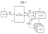
- FIG. 1 shows a conventional interface processor arrangement for a gateway with a microprocessor (host processor) 2, which with an interface device (Physical Interface Device) 4 via a media independent interface (MII) is connected.
- the host processor 2 is also included a bank of subsystems 6 connected.
- the subsystems 6 can for example, digital signal processors (DSP) that Process RTP data packets.
- DSP digital signal processors
- SDRAM memory 8 in which incoming data packets can be buffered.
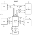
- FIG. 2 shows an arrangement 10 according to the invention for a gateway with a host processor 12, an interface device 14 and a data packet mediator (packet router) 16.
- the interface device 14 is both with the host processor 12 as well as with the data packet intermediary 16 MII connected.
- the data packet switch 16 is with the Host processor 12, with subsystems (DSP) 18, a buffer (SRAM) 20 and an address memory (CAM) 22 connected.
- DSP subsystems
- SRAM buffer
- CAM address memory
- the data packet switch 16 receives from the interface device 14 all data packets intended for this arrangement 10. It compares the addresses of the data packets with one List of addresses that are stored in the address memory 22. Data packets with such an address are sent by the data packet broker 16 directly to the corresponding subsystem 18 forwarded. Data packets whose address is not with a Address from the address memory 22 matches are from forwarded to the packet processor 16 to the microprocessor 12.
- the address memory 22 is a so-called CAM (content address memory) and is used for storing the connection data needed. It is possible to use a commercially available CAM. With a number of 256 or more active RTP connections it is necessary to quickly make a decision to hit where the packets should go.
- the CAM functionality can within the data packet switch 16 with dedicated RAM cells (Read and Modify Memory) become. Address memory 22 must be from the host processor 12 are managed and then stands for the distribution or Routing of the RTP packets available. It's not necessary the host processor 12 with an address memory 22, which for an Ethernet is suitable to equip.
- An external memory 20 serves as a buffer for the data packets in both directions.
- an SRAM or DRAM interface is used.
- An SRAM has that higher access speed, but is above a certain one Size much more expensive than a DRAM.
- the speed disadvantages of the DRAM can be achieved by using a cache and / or minimize a pipeline.
- the effort for a speed-optimized DRAM implementation is essential higher than for a SRAM variant. If the memory 20 with Realized SRAM, there is also enough fast memory available for the exchange between internal modules.
- a Estimation results in a need of around 2 to 4 Mbytes 256 channels for the special case of RTP voice packets.
- the Data bus width should be the host processor 12 and the data structures be adjusted. The number of address lines depends on the address space that is provided must become.
- the registers within the buffer 20, which for the Control of the modules are necessary must be read directly and can be described.
- the data area is located in the external memory 20. There are memory areas for each channel, which the host processor 12 can access. It it would be possible to enter a channel number first must and the data packet switch 16 then the data for the Host processor 12 provides them in the respective Transfers memory structure.
- the host processor 12 must make settings in each DSP 18 can. But it is not necessary that it be directly on accesses the DSP 18.
- the buffer store 20 can also be located here be used.
- the structure can be handled by the data packet intermediary 16 are passed on to the DSPs 18.
- the RTP packets an active connection when using the data packet broker 16 no longer via the host processor 12 transfer.
- Fig. 3 shows a sketch of signal lines in an inventive Arrangement in the receiving direction.
- both the microprocessor 12 as well as the data packet switch 16 with the interface device 14 each connected via an MII. Both MII interfaces can on the same interface device 14 work.
- the microprocessor 12 or the data packet switch 16 signals for example with an RSTRT signal the beginning of a valid Ethernet packet.
- the data packet switch 16 "listens" to the Ethernet interface 14 with and generated after evaluation of all information the reject signal for the microprocessor 12 or your own MAC (Media Access Control). Will the reject signal before generated at the end of the Ethernet packet, the used Buffer descriptors used for new packets. The data in the buffer are discarded. In the case of an implementation with a Motorola PowerPC the processor core is not with costly address comparisons. Immediately upon receipt of the Data is decided whether the Ethernet packet is now processed must be or not. The RSTRT signal marks the Start of the receive address of the Ethernet packet. So it will Control logic always re-synchronized to the incoming packets.
- the RSTRT signal marks the Start of the receive address of the Ethernet packet. So it will Control logic always re-synchronized to the incoming packets.
- Fig. 4 also shows the arrangement as Fig. 3, however with the signal lines in the transmission direction.
- control of the collision signals ensures synchronization both MACs, host processor 12 and data packet broker 16, on an interface device 14. This control is taken over by the data packet switch 16.
- a TX_EN signal is generated by the microprocessor 12. It marks a valid data nibble on the MI interface in the direction of transmission. If the packet mediator 16 A data packet is being sent is being processed in the microprocessor 12 with a CRS (Carrier Receive Sense) signal and a COL (Collision) signal signals that the transmission medium is currently is used. The MAC of the microprocessor 12 thus goes into the collision cycle and repeats its last transmission.
- CRS Carrier Receive Sense
- COL collision
- the address memory 22 offers the possibility of the incoming addresses to compare with his entries. Within the shortest Time can be signaled whether the address is in the address memory 22 stands or not. This comparison is independent of the software on the host processor 12 (from FIG. 2).
- the address memory For example, 12 can be a Motorola MCM69C232 his. This can manage 4096 entries, each 64 bits deep. The average access time is 160 ns at a clock rate of 50 MHz.
- the search for a valid address must be in three steps. First of all, in the incoming Ethernet frame 30 searched for a valid Ethernet address become. The Ethernet address is stored in box 31. In box 32 it is checked whether it is a valid address is. If the address is not correct, it is done immediately a reject 33 for both MACs. Next in box 34 in the frame the IP address is filtered out in order to Check box 35 for validity. If this is not correct, it is done the reject 33 for both MACs.
- the position is the UDP destination port is not fixed. It means that the packet switch 16 resumes on the frame must set the position of the UDP destination port. Because it there are many active UDP connections, will be found a valid UDP destination port the address memory 22 used. Therefore, the UDP address is in box 36 filtered out and in the box 37 to the address memory 22 to hand over. In box 38, this checks the UDP address, i.e. it compares the transferred UDP address with that in Address memory stored addresses. If the address memory 22 has not found a valid UDP address, is in the Box 39 internally generates a reject signal. If the address cache 22 A valid UDP destination port was found has a reject signal for the MAC of the Microprocessor 12 generated.
- the Address buffer 22 can have a depth of 64 bits the remaining 32 bits for storing additional data, For example, connection data, port, DSP, etc. can be used.
- the match data is sent in box 41 to the memory manager transferred and the address memory 22 offers the possibility output this match data.
- the box 42 will the storage address for RTP packets at the MRC of the data packet switch transmitted. This can now process the data for further processing use.
- FIG. 6 schematically shows a process control for several Processes X0 to X5 in a data packet switch according to the invention (16 from Fig. 2).
- the individual accesses to the different parts of the data packet intermediary 16 must be controlled.
- Several processes can do this access resources simultaneously, for example need multiple processes on the memory (20 of FIG. 2) can write and read. There shouldn't be any blockages here, Collision or conflict is coming. Collisions can be avoided for example by using buffers and / or one Avoid pipeline. These are inside the chip to make it unnecessary Avoid traffic on the memory 20.
- read access should always done as a burst. Only the required one may be written Amount of data. Buffer and internal structures can but can also be designed so that here a burst on the Memory 20 is possible.
- the individual processes X0 - X5 are assigned one memory block or several memory blocks.
- the size of the memory blocks is not variable. The size corresponds to that of a burst on the external memory 20.
- An additional priority is achieved by the pipeline and the entry point.
- the WAIT cycles (T -2 , T -4 ) are to be designed so that all processes X0 to X5 are operated. WAIT cycles are only inserted if an event is pending at the following entry point. Processes X0 and X1 have very low priority. Process X5 has the highest priority, but only a small amount of data.
- the overview in FIG. 6 does not evaluate the distribution of priorities of the individual modules within the data packet switch 16.
- FIG. 7 is a second embodiment of an inventive Arrangement with two data packet switches 16, 16 'shown. It differs from the first embodiment, which was described in Fig. 2 by a additional data packet switch 16 ', which also (like the data packet switch 16) both with the interface device 14 as well as connected to the host processor 12 is.
- the data packet switch 16 ' has its own address memory 22 'to which it is connected. Still is the data packet switch 16 'is connected to a memory 20', which is used for the temporary storage of data packets.
- a Bank of further subsystems or DSPs 18 ' is also included connected to the data packet switch 16 '.
- the host processor 12 can be two different in the arrangement from FIG. 7 Manage address lists - one in the address memory 22, the second in the address memory 22 '. Therefore can Data packets from different addresses to different Subsystems 18 and 18 'are forwarded.
- the data packet broker 16 data packets with video information Subsystems 18 Processing Video Data 18 forwards.
- the data packet broker 16 ' for example, data packets with voice information forward to corresponding subsystems 18 ', the voice data packets processed.
- the two data packet switches are 16 and 16 'arranged parallel to each other.
- the advantage is that both data packet switches 16, 16 'without Time delay each of the data packets from the data stream can filter out their address in the respective address memory 22 or 22 'is stored.
- the Host processor 12 of this arrangement 10 all data packets there he the data packets filtered out by the data packet mediator 16 receives from the data packet switch 16 '. He also receives the data packets filtered out by the data packet mediator 16 ' from the data packet intermediary 16.
- Advantageous in this arrangement 10 ' is only the fact that the subsystems 18th or 18 'with only a slight time delay for them receive certain data packets.
Landscapes
- Engineering & Computer Science (AREA)
- Computer Networks & Wireless Communication (AREA)
- Signal Processing (AREA)
- Data Exchanges In Wide-Area Networks (AREA)
Applications Claiming Priority (2)
| Application Number | Priority Date | Filing Date | Title |
|---|---|---|---|
| DE10139936A DE10139936B4 (de) | 2001-08-14 | 2001-08-14 | Verfahren und Anordnung zur Steuerung von Datenpaketen |
| DE10139936 | 2001-08-14 |
Publications (3)
| Publication Number | Publication Date |
|---|---|
| EP1284561A2 true EP1284561A2 (fr) | 2003-02-19 |
| EP1284561A3 EP1284561A3 (fr) | 2004-03-24 |
| EP1284561B1 EP1284561B1 (fr) | 2006-03-22 |
Family
ID=7695434
Family Applications (1)
| Application Number | Title | Priority Date | Filing Date |
|---|---|---|---|
| EP02102025A Expired - Lifetime EP1284561B1 (fr) | 2001-08-14 | 2002-07-11 | Procedé et dispositif pour commander les paquets de données |
Country Status (3)
| Country | Link |
|---|---|
| US (1) | US7209485B2 (fr) |
| EP (1) | EP1284561B1 (fr) |
| DE (2) | DE10139936B4 (fr) |
Cited By (4)
| Publication number | Priority date | Publication date | Assignee | Title |
|---|---|---|---|---|
| CN1086399C (zh) * | 1997-08-22 | 2002-06-19 | 希巴特殊化学控股公司 | 由α-氨基苯乙酮光致生成胺 |
| GB2413872A (en) * | 2002-05-13 | 2005-11-09 | Nvidia Corp | An integrated network of processors |
| GB2405244B (en) * | 2002-05-13 | 2006-01-04 | Nvidia Corp | Method and apparatus for providing an integrated network of processors |
| WO2007088397A3 (fr) * | 2006-01-31 | 2007-09-27 | Roke Manor Research | Procédé de filtrage de trafic à haut débit |
Families Citing this family (53)
| Publication number | Priority date | Publication date | Assignee | Title |
|---|---|---|---|---|
| US7397797B2 (en) * | 2002-12-13 | 2008-07-08 | Nvidia Corporation | Method and apparatus for performing network processing functions |
| US7913294B1 (en) | 2003-06-24 | 2011-03-22 | Nvidia Corporation | Network protocol processing for filtering packets |
| US20070127438A1 (en) * | 2005-12-01 | 2007-06-07 | Scott Newman | Method and system for processing telephone technical support |
| US20080046966A1 (en) * | 2006-08-03 | 2008-02-21 | Richard Chuck Rhoades | Methods and apparatus to process network messages |
| US8543243B2 (en) | 2008-10-27 | 2013-09-24 | Lennox Industries, Inc. | System and method of use for a user interface dashboard of a heating, ventilation and air conditioning network |
| US8452906B2 (en) | 2008-10-27 | 2013-05-28 | Lennox Industries, Inc. | Communication protocol system and method for a distributed-architecture heating, ventilation and air conditioning network |
| US9377768B2 (en) | 2008-10-27 | 2016-06-28 | Lennox Industries Inc. | Memory recovery scheme and data structure in a heating, ventilation and air conditioning network |
| US8694164B2 (en) | 2008-10-27 | 2014-04-08 | Lennox Industries, Inc. | Interactive user guidance interface for a heating, ventilation and air conditioning system |
| US8442693B2 (en) | 2008-10-27 | 2013-05-14 | Lennox Industries, Inc. | System and method of use for a user interface dashboard of a heating, ventilation and air conditioning network |
| US8774210B2 (en) | 2008-10-27 | 2014-07-08 | Lennox Industries, Inc. | Communication protocol system and method for a distributed-architecture heating, ventilation and air conditioning network |
| US8352081B2 (en) | 2008-10-27 | 2013-01-08 | Lennox Industries Inc. | Communication protocol system and method for a distributed-architecture heating, ventilation and air conditioning network |
| US8977794B2 (en) | 2008-10-27 | 2015-03-10 | Lennox Industries, Inc. | Communication protocol system and method for a distributed-architecture heating, ventilation and air conditioning network |
| US8295981B2 (en) | 2008-10-27 | 2012-10-23 | Lennox Industries Inc. | Device commissioning in a heating, ventilation and air conditioning network |
| US8855825B2 (en) | 2008-10-27 | 2014-10-07 | Lennox Industries Inc. | Device abstraction system and method for a distributed-architecture heating, ventilation and air conditioning system |
| US9261888B2 (en) | 2008-10-27 | 2016-02-16 | Lennox Industries Inc. | System and method of use for a user interface dashboard of a heating, ventilation and air conditioning network |
| US8725298B2 (en) | 2008-10-27 | 2014-05-13 | Lennox Industries, Inc. | Alarm and diagnostics system and method for a distributed architecture heating, ventilation and conditioning network |
| US9632490B2 (en) | 2008-10-27 | 2017-04-25 | Lennox Industries Inc. | System and method for zoning a distributed architecture heating, ventilation and air conditioning network |
| US8762666B2 (en) | 2008-10-27 | 2014-06-24 | Lennox Industries, Inc. | Backup and restoration of operation control data in a heating, ventilation and air conditioning network |
| US8452456B2 (en) | 2008-10-27 | 2013-05-28 | Lennox Industries Inc. | System and method of use for a user interface dashboard of a heating, ventilation and air conditioning network |
| US8433446B2 (en) | 2008-10-27 | 2013-04-30 | Lennox Industries, Inc. | Alarm and diagnostics system and method for a distributed-architecture heating, ventilation and air conditioning network |
| US8661165B2 (en) | 2008-10-27 | 2014-02-25 | Lennox Industries, Inc. | Device abstraction system and method for a distributed architecture heating, ventilation and air conditioning system |
| US8788100B2 (en) | 2008-10-27 | 2014-07-22 | Lennox Industries Inc. | System and method for zoning a distributed-architecture heating, ventilation and air conditioning network |
| US9651925B2 (en) | 2008-10-27 | 2017-05-16 | Lennox Industries Inc. | System and method for zoning a distributed-architecture heating, ventilation and air conditioning network |
| US8437877B2 (en) | 2008-10-27 | 2013-05-07 | Lennox Industries Inc. | System recovery in a heating, ventilation and air conditioning network |
| US8655491B2 (en) | 2008-10-27 | 2014-02-18 | Lennox Industries Inc. | Alarm and diagnostics system and method for a distributed architecture heating, ventilation and air conditioning network |
| US8892797B2 (en) | 2008-10-27 | 2014-11-18 | Lennox Industries Inc. | Communication protocol system and method for a distributed-architecture heating, ventilation and air conditioning network |
| US9432208B2 (en) | 2008-10-27 | 2016-08-30 | Lennox Industries Inc. | Device abstraction system and method for a distributed architecture heating, ventilation and air conditioning system |
| US8600559B2 (en) | 2008-10-27 | 2013-12-03 | Lennox Industries Inc. | Method of controlling equipment in a heating, ventilation and air conditioning network |
| US8655490B2 (en) | 2008-10-27 | 2014-02-18 | Lennox Industries, Inc. | System and method of use for a user interface dashboard of a heating, ventilation and air conditioning network |
| US9152155B2 (en) | 2008-10-27 | 2015-10-06 | Lennox Industries Inc. | Device abstraction system and method for a distributed-architecture heating, ventilation and air conditioning system |
| US8239066B2 (en) | 2008-10-27 | 2012-08-07 | Lennox Industries Inc. | System and method of use for a user interface dashboard of a heating, ventilation and air conditioning network |
| US8798796B2 (en) | 2008-10-27 | 2014-08-05 | Lennox Industries Inc. | General control techniques in a heating, ventilation and air conditioning network |
| US9268345B2 (en) | 2008-10-27 | 2016-02-23 | Lennox Industries Inc. | System and method of use for a user interface dashboard of a heating, ventilation and air conditioning network |
| US8437878B2 (en) | 2008-10-27 | 2013-05-07 | Lennox Industries Inc. | Alarm and diagnostics system and method for a distributed architecture heating, ventilation and air conditioning network |
| US8560125B2 (en) | 2008-10-27 | 2013-10-15 | Lennox Industries | Communication protocol system and method for a distributed-architecture heating, ventilation and air conditioning network |
| US8874815B2 (en) | 2008-10-27 | 2014-10-28 | Lennox Industries, Inc. | Communication protocol system and method for a distributed architecture heating, ventilation and air conditioning network |
| US8802981B2 (en) | 2008-10-27 | 2014-08-12 | Lennox Industries Inc. | Flush wall mount thermostat and in-set mounting plate for a heating, ventilation and air conditioning system |
| US8548630B2 (en) | 2008-10-27 | 2013-10-01 | Lennox Industries, Inc. | Alarm and diagnostics system and method for a distributed-architecture heating, ventilation and air conditioning network |
| US8564400B2 (en) | 2008-10-27 | 2013-10-22 | Lennox Industries, Inc. | Communication protocol system and method for a distributed-architecture heating, ventilation and air conditioning network |
| US8994539B2 (en) | 2008-10-27 | 2015-03-31 | Lennox Industries, Inc. | Alarm and diagnostics system and method for a distributed-architecture heating, ventilation and air conditioning network |
| US8463442B2 (en) | 2008-10-27 | 2013-06-11 | Lennox Industries, Inc. | Alarm and diagnostics system and method for a distributed architecture heating, ventilation and air conditioning network |
| US8352080B2 (en) | 2008-10-27 | 2013-01-08 | Lennox Industries Inc. | Communication protocol system and method for a distributed-architecture heating, ventilation and air conditioning network |
| US8600558B2 (en) | 2008-10-27 | 2013-12-03 | Lennox Industries Inc. | System recovery in a heating, ventilation and air conditioning network |
| US8744629B2 (en) | 2008-10-27 | 2014-06-03 | Lennox Industries Inc. | System and method of use for a user interface dashboard of a heating, ventilation and air conditioning network |
| US8255086B2 (en) | 2008-10-27 | 2012-08-28 | Lennox Industries Inc. | System recovery in a heating, ventilation and air conditioning network |
| US8615326B2 (en) | 2008-10-27 | 2013-12-24 | Lennox Industries Inc. | System and method of use for a user interface dashboard of a heating, ventilation and air conditioning network |
| US8463443B2 (en) | 2008-10-27 | 2013-06-11 | Lennox Industries, Inc. | Memory recovery scheme and data structure in a heating, ventilation and air conditioning network |
| US9325517B2 (en) | 2008-10-27 | 2016-04-26 | Lennox Industries Inc. | Device abstraction system and method for a distributed-architecture heating, ventilation and air conditioning system |
| US9678486B2 (en) | 2008-10-27 | 2017-06-13 | Lennox Industries Inc. | Device abstraction system and method for a distributed-architecture heating, ventilation and air conditioning system |
| USD648642S1 (en) | 2009-10-21 | 2011-11-15 | Lennox Industries Inc. | Thin cover plate for an electronic system controller |
| USD648641S1 (en) | 2009-10-21 | 2011-11-15 | Lennox Industries Inc. | Thin cover plate for an electronic system controller |
| US8260444B2 (en) | 2010-02-17 | 2012-09-04 | Lennox Industries Inc. | Auxiliary controller of a HVAC system |
| US10331586B2 (en) * | 2015-10-30 | 2019-06-25 | Samsung Electronics Co., Ltd. | Nonvolatile memory device for providing fast booting and system including the same |
Family Cites Families (4)
| Publication number | Priority date | Publication date | Assignee | Title |
|---|---|---|---|---|
| US6157644A (en) * | 1997-10-07 | 2000-12-05 | Northern Telecom Limited | Method and apparatus for accelerating OSI layer 3 routers |
| US6678246B1 (en) * | 1999-07-07 | 2004-01-13 | Nortel Networks Limited | Processing data packets |
| EP1238489B1 (fr) * | 1999-12-13 | 2008-03-05 | Broadcom Corporation | Passerelle vocale sur ip avec une synchronisation vocale en aval |
| FI112308B (fi) * | 2000-09-14 | 2003-11-14 | Nokia Corp | Protokollan käsittelyn jakaminen |
-
2001
- 2001-08-14 DE DE10139936A patent/DE10139936B4/de not_active Expired - Fee Related
-
2002
- 2002-07-11 DE DE50206134T patent/DE50206134D1/de not_active Expired - Lifetime
- 2002-07-11 EP EP02102025A patent/EP1284561B1/fr not_active Expired - Lifetime
- 2002-08-14 US US10/218,175 patent/US7209485B2/en not_active Expired - Fee Related
Cited By (7)
| Publication number | Priority date | Publication date | Assignee | Title |
|---|---|---|---|---|
| CN1086399C (zh) * | 1997-08-22 | 2002-06-19 | 希巴特殊化学控股公司 | 由α-氨基苯乙酮光致生成胺 |
| GB2413872A (en) * | 2002-05-13 | 2005-11-09 | Nvidia Corp | An integrated network of processors |
| GB2405244B (en) * | 2002-05-13 | 2006-01-04 | Nvidia Corp | Method and apparatus for providing an integrated network of processors |
| GB2413872B (en) * | 2002-05-13 | 2006-03-01 | Nvidia Corp | Method and apparatus for providing an integrated network of processors |
| US7383352B2 (en) | 2002-05-13 | 2008-06-03 | Nvidia Corporation | Method and apparatus for providing an integrated network of processors |
| US7620738B2 (en) | 2002-05-13 | 2009-11-17 | Nvidia Corporation | Method and apparatus for providing an integrated network of processors |
| WO2007088397A3 (fr) * | 2006-01-31 | 2007-09-27 | Roke Manor Research | Procédé de filtrage de trafic à haut débit |
Also Published As
| Publication number | Publication date |
|---|---|
| US7209485B2 (en) | 2007-04-24 |
| DE10139936A1 (de) | 2003-04-24 |
| EP1284561A3 (fr) | 2004-03-24 |
| DE10139936B4 (de) | 2005-04-28 |
| EP1284561B1 (fr) | 2006-03-22 |
| US20030035431A1 (en) | 2003-02-20 |
| DE50206134D1 (de) | 2006-05-11 |
Similar Documents
| Publication | Publication Date | Title |
|---|---|---|
| EP1284561B1 (fr) | Procedé et dispositif pour commander les paquets de données | |
| DE60202136T2 (de) | Cache-eintrag-auswahlverfahren und -vorrichtung | |
| DE69332558T2 (de) | Multiport-Brücke für lokales Netz | |
| DE69917555T2 (de) | Vermittlungseinrichtung mit mehrstufiger Warteschlangeschema | |
| DE69324204T2 (de) | Aufsuchen von Adressen bei Paketübertragung mittels Hashing und eines inhaltsadressierten Speichers | |
| DE69325557T2 (de) | Paketformat in Knotenpunkt für ein Datenübertragungssystem | |
| DE69810132T2 (de) | Multiport drams mit internen cache-speichern | |
| DE60203380T2 (de) | Verfahren und vorrichtung zur mehrfachsendung | |
| DE60021846T2 (de) | Leitweglenkungsanordnung | |
| DE69820084T2 (de) | Netzwerkvorrichtung und Verfahren zur Reduzierung der System-Latenz | |
| EP2882144B1 (fr) | Procédé et agencement de filtre destinés à filtrer des informations entrantes à l'aide d'un bus de données en série d'un réseau de communication dans un abonné du réseau | |
| DE69505826T2 (de) | Netzwerkübertragungseinheit mit einer adaptiven wegsucheinheit | |
| DE69106414T2 (de) | Verfahren zur Steuerung des Zugangs zu einem Bus in einem (DBDQ)-Netzwerk, bestehend aus zwei Bussen und einer verteilten Warteschlange. | |
| DE60100927T2 (de) | Verbesserter Internet Protocolpaketrouter | |
| DE69022942T2 (de) | Schrittablauf innerhalb eines Knotens für ein schnelles Netzwerk. | |
| DE69129952T2 (de) | Vorrichtung zur Paketübermittlungsregulierung | |
| DE102022200567A1 (de) | Verarbeitung von paketen in ungeordneter reihenfolge | |
| DE602005003492T2 (de) | Verfahren, Vorrichtung und System zum synchronisierten Kombinieren von Paketdaten | |
| DE60014178T2 (de) | Vorrichtung und verfahren zur speicherteilung in einer konfiguration mit einzelring-datenbusverbindung | |
| DE102018204861A1 (de) | Einzelner Umsetzungstabelleneintrag für symmetrische Flüsse | |
| EP0351014A2 (fr) | Réseau de commutation pour système de commutation | |
| DE60112680T2 (de) | Netzwerkerweiterungsmodul | |
| DE102024201894A1 (de) | Filter für eine konvertierte weiterleitungstabelle in einem schienenoptimierten netzwerk | |
| DE10296700T5 (de) | Flusssteuerungssystem zur Verringerung der Speicherpufferanforderungen und zur Herstellung einer Prioritätsbedienung zwischen Netzen | |
| DE60207687T2 (de) | Verfahren und vorrichtung zum klassifizieren von abfrageknoten |
Legal Events
| Date | Code | Title | Description |
|---|---|---|---|
| PUAI | Public reference made under article 153(3) epc to a published international application that has entered the european phase |
Free format text: ORIGINAL CODE: 0009012 |
|
| AK | Designated contracting states |
Designated state(s): AT BE BG CH CY CZ DE DK EE ES FI FR GB GR IE IT LI LU MC NL PT SE SK TR |
|
| AX | Request for extension of the european patent |
Extension state: AL LT LV MK RO SI |
|
| PUAL | Search report despatched |
Free format text: ORIGINAL CODE: 0009013 |
|
| AK | Designated contracting states |
Kind code of ref document: A3 Designated state(s): AT BE BG CH CY CZ DE DK EE ES FI FR GB GR IE IT LI LU MC NL PT SE SK TR |
|
| AX | Request for extension of the european patent |
Extension state: AL LT LV MK RO SI |
|
| RIC1 | Information provided on ipc code assigned before grant |
Ipc: 7H 04L 29/06 B Ipc: 7H 04L 12/56 B Ipc: 7H 04L 12/64 A |
|
| 17P | Request for examination filed |
Effective date: 20040419 |
|
| 17Q | First examination report despatched |
Effective date: 20040513 |
|
| AKX | Designation fees paid |
Designated state(s): DE FR GB IT |
|
| GRAP | Despatch of communication of intention to grant a patent |
Free format text: ORIGINAL CODE: EPIDOSNIGR1 |
|
| GRAS | Grant fee paid |
Free format text: ORIGINAL CODE: EPIDOSNIGR3 |
|
| GRAA | (expected) grant |
Free format text: ORIGINAL CODE: 0009210 |
|
| AK | Designated contracting states |
Kind code of ref document: B1 Designated state(s): DE FR GB IT |
|
| REG | Reference to a national code |
Ref country code: GB Ref legal event code: FG4D Free format text: NOT ENGLISH |
|
| REF | Corresponds to: |
Ref document number: 50206134 Country of ref document: DE Date of ref document: 20060511 Kind code of ref document: P |
|
| GBT | Gb: translation of ep patent filed (gb section 77(6)(a)/1977) |
Effective date: 20060619 |
|
| ET | Fr: translation filed | ||
| PLBE | No opposition filed within time limit |
Free format text: ORIGINAL CODE: 0009261 |
|
| STAA | Information on the status of an ep patent application or granted ep patent |
Free format text: STATUS: NO OPPOSITION FILED WITHIN TIME LIMIT |
|
| 26N | No opposition filed |
Effective date: 20061227 |
|
| REG | Reference to a national code |
Ref country code: GB Ref legal event code: 732E Free format text: REGISTERED BETWEEN 20121025 AND 20121031 |
|
| REG | Reference to a national code |
Ref country code: FR Ref legal event code: TP Owner name: SIEMENS ENTERPRISE COMMUNICATIONS GMBH & CO. K, DE Effective date: 20130108 |
|
| REG | Reference to a national code |
Ref country code: DE Ref legal event code: R082 Ref document number: 50206134 Country of ref document: DE Representative=s name: FRITZSCHE PATENT, DE |
|
| REG | Reference to a national code |
Ref country code: DE Ref legal event code: R081 Ref document number: 50206134 Country of ref document: DE Owner name: SIEMENS ENTERPRISE COMMUNICATIONS GMBH & CO. K, DE Free format text: FORMER OWNER: SIEMENS AKTIENGESELLSCHAFT, 80333 MUENCHEN, DE Effective date: 20130313 Ref country code: DE Ref legal event code: R082 Ref document number: 50206134 Country of ref document: DE Representative=s name: FRITZSCHE PATENT, DE Effective date: 20130313 Ref country code: DE Ref legal event code: R081 Ref document number: 50206134 Country of ref document: DE Owner name: UNIFY GMBH & CO. KG, DE Free format text: FORMER OWNER: SIEMENS AKTIENGESELLSCHAFT, 80333 MUENCHEN, DE Effective date: 20130313 Ref country code: DE Ref legal event code: R082 Ref document number: 50206134 Country of ref document: DE Representative=s name: FRITZSCHE PATENTANWAELTE, DE Effective date: 20130313 |
|
| REG | Reference to a national code |
Ref country code: GB Ref legal event code: 746 Effective date: 20130418 |
|
| REG | Reference to a national code |
Ref country code: DE Ref legal event code: R082 Ref document number: 50206134 Country of ref document: DE Representative=s name: FRITZSCHE PATENT, DE |
|
| REG | Reference to a national code |
Ref country code: DE Ref legal event code: R081 Ref document number: 50206134 Country of ref document: DE Owner name: UNIFY GMBH & CO. KG, DE Free format text: FORMER OWNER: SIEMENS ENTERPRISE COMMUNICATIONS GMBH & CO. KG, 81379 MUENCHEN, DE Effective date: 20131112 Ref country code: DE Ref legal event code: R082 Ref document number: 50206134 Country of ref document: DE Representative=s name: FRITZSCHE PATENT, DE Effective date: 20131112 Ref country code: DE Ref legal event code: R082 Ref document number: 50206134 Country of ref document: DE Representative=s name: FRITZSCHE PATENTANWAELTE, DE Effective date: 20131112 |
|
| REG | Reference to a national code |
Ref country code: FR Ref legal event code: CD Owner name: UNIFY GMBH & CO.KG, DE Effective date: 20140429 |
|
| PGFP | Annual fee paid to national office [announced via postgrant information from national office to epo] |
Ref country code: IT Payment date: 20150728 Year of fee payment: 14 |
|
| REG | Reference to a national code |
Ref country code: FR Ref legal event code: PLFP Year of fee payment: 15 |
|
| PG25 | Lapsed in a contracting state [announced via postgrant information from national office to epo] |
Ref country code: IT Free format text: LAPSE BECAUSE OF NON-PAYMENT OF DUE FEES Effective date: 20150711 |
|
| REG | Reference to a national code |
Ref country code: DE Ref legal event code: R082 Ref document number: 50206134 Country of ref document: DE Representative=s name: FRITZSCHE PATENTANWAELTE, DE Ref country code: DE Ref legal event code: R081 Ref document number: 50206134 Country of ref document: DE Owner name: UNIFY GMBH & CO. KG, DE Free format text: FORMER OWNER: UNIFY GMBH & CO. KG, 81379 MUENCHEN, DE |
|
| REG | Reference to a national code |
Ref country code: FR Ref legal event code: PLFP Year of fee payment: 16 |
|
| PG25 | Lapsed in a contracting state [announced via postgrant information from national office to epo] |
Ref country code: IT Free format text: LAPSE BECAUSE OF NON-PAYMENT OF DUE FEES Effective date: 20160711 |
|
| PGFP | Annual fee paid to national office [announced via postgrant information from national office to epo] |
Ref country code: IT Payment date: 20150728 Year of fee payment: 14 |
|
| PGRI | Patent reinstated in contracting state [announced from national office to epo] |
Ref country code: IT Effective date: 20170520 |
|
| PG25 | Lapsed in a contracting state [announced via postgrant information from national office to epo] |
Ref country code: IT Free format text: LAPSE BECAUSE OF NON-PAYMENT OF DUE FEES Effective date: 20160711 |
|
| PGRI | Patent reinstated in contracting state [announced from national office to epo] |
Ref country code: IT Effective date: 20170520 |
|
| REG | Reference to a national code |
Ref country code: FR Ref legal event code: PLFP Year of fee payment: 17 |
|
| PGFP | Annual fee paid to national office [announced via postgrant information from national office to epo] |
Ref country code: DE Payment date: 20180725 Year of fee payment: 17 Ref country code: FR Payment date: 20180723 Year of fee payment: 17 |
|
| PGFP | Annual fee paid to national office [announced via postgrant information from national office to epo] |
Ref country code: GB Payment date: 20180725 Year of fee payment: 17 |
|
| REG | Reference to a national code |
Ref country code: DE Ref legal event code: R119 Ref document number: 50206134 Country of ref document: DE |
|
| GBPC | Gb: european patent ceased through non-payment of renewal fee |
Effective date: 20190711 |
|
| PG25 | Lapsed in a contracting state [announced via postgrant information from national office to epo] |
Ref country code: GB Free format text: LAPSE BECAUSE OF NON-PAYMENT OF DUE FEES Effective date: 20190711 Ref country code: DE Free format text: LAPSE BECAUSE OF NON-PAYMENT OF DUE FEES Effective date: 20200201 |
|
| PG25 | Lapsed in a contracting state [announced via postgrant information from national office to epo] |
Ref country code: FR Free format text: LAPSE BECAUSE OF NON-PAYMENT OF DUE FEES Effective date: 20190731 |