EP1284592A2 - Vermittlungseinrichtung mit einem Gehäuse, dessen Wärmeleitfähigkeit verbessert ist - Google Patents
Vermittlungseinrichtung mit einem Gehäuse, dessen Wärmeleitfähigkeit verbessert ist Download PDFInfo
- Publication number
- EP1284592A2 EP1284592A2 EP02018497A EP02018497A EP1284592A2 EP 1284592 A2 EP1284592 A2 EP 1284592A2 EP 02018497 A EP02018497 A EP 02018497A EP 02018497 A EP02018497 A EP 02018497A EP 1284592 A2 EP1284592 A2 EP 1284592A2
- Authority
- EP
- European Patent Office
- Prior art keywords
- housing
- wall
- telecommunication device
- hollow space
- refrigerant
- Prior art date
- Legal status (The legal status is an assumption and is not a legal conclusion. Google has not performed a legal analysis and makes no representation as to the accuracy of the status listed.)
- Withdrawn
Links
Images


Classifications
-
- H—ELECTRICITY
- H05—ELECTRIC TECHNIQUES NOT OTHERWISE PROVIDED FOR
- H05K—PRINTED CIRCUITS; CASINGS OR CONSTRUCTIONAL DETAILS OF ELECTRIC APPARATUS; MANUFACTURE OF ASSEMBLAGES OF ELECTRICAL COMPONENTS
- H05K5/00—Casings, cabinets or drawers for electric apparatus
- H05K5/06—Hermetically-sealed casings
- H05K5/068—Hermetically-sealed casings having a pressure compensation device, e.g. membrane
-
- H—ELECTRICITY
- H05—ELECTRIC TECHNIQUES NOT OTHERWISE PROVIDED FOR
- H05K—PRINTED CIRCUITS; CASINGS OR CONSTRUCTIONAL DETAILS OF ELECTRIC APPARATUS; MANUFACTURE OF ASSEMBLAGES OF ELECTRICAL COMPONENTS
- H05K7/00—Constructional details common to different types of electric apparatus
- H05K7/20—Modifications to facilitate cooling, ventilating, or heating
- H05K7/20009—Modifications to facilitate cooling, ventilating, or heating using a gaseous coolant in electronic enclosures
- H05K7/20127—Natural convection
-
- H—ELECTRICITY
- H05—ELECTRIC TECHNIQUES NOT OTHERWISE PROVIDED FOR
- H05K—PRINTED CIRCUITS; CASINGS OR CONSTRUCTIONAL DETAILS OF ELECTRIC APPARATUS; MANUFACTURE OF ASSEMBLAGES OF ELECTRICAL COMPONENTS
- H05K7/00—Constructional details common to different types of electric apparatus
- H05K7/20—Modifications to facilitate cooling, ventilating, or heating
- H05K7/2039—Modifications to facilitate cooling, ventilating, or heating characterised by the heat transfer by conduction from the heat generating element to a dissipating body
- H05K7/20436—Inner thermal coupling elements in heat dissipating housings, e.g. protrusions or depressions integrally formed in the housing
Definitions
- the present invention relates to a telecommunication device including a housing having improved heat conductivity and, more particularly, to a heat radiation structure of the housing of a telecommunication device.
- a gas-assist injection molding (GAIM) technique is widely used for molding a variety of plastic materials because the GAIM technique provides an improved appearance without an undesired projection or warp on the surface, and an improved strength and a light weight due to the structure of the hollow space.
- GAIM gas-assist injection molding
- the interior accessories of a vehicle or television cabinets are manufactured by using the GAIM technique due to the improvement of the quality in the injection-molded parts, as well as the needs for smaller weight and dimensional accuracy in the interior accessories and the television cabinets.
- a telecommunication device such as a base station of a personal handyphone system, which is generally attached onto a mast, is requested to radiate the internal heat generated by the integrated circuit therein, and have a housing with a smaller weight and smaller dimensions for achieving a lower cost.
- the GAIM technique is not used heretofore in manufacture of the housing through which efficient heat radiation is requested, because the plastic material formed by the GAIM technique has lower heat conductivity compared to a metallic material.
- Aluminum is generally used heretofore as the material for a housing of the base station of a personal handyphone system due to the excellent heat conductivity thereof.
- the aluminum housing is generally formed as a solid body, the heat radiation capability of the aluminum housing is limited by and does not exceed the heat conductivity property of the aluminum metal.
- Patent Publication JP-A-7-094881 describes a heat radiation structure of an electric equipment such as a computer.
- the heat radiation structure includes a cooling device for cooling therein refrigerant, a plurality of cooling modules through which the refrigerant passes, a tube system including supply paths and return paths between the cooling device and the cooling modules for circulating the refrigerant, and a plurality of pivot valves each disposed for a return path of a corresponding cooling module and having an extendable rod for controlling the flow rate of the refrigerant passing through the pivot valve based on the temperature of the refrigerant.
- the heat radiation structure described in the above publication has a complicated structure due to provision of the pivot valves for controlling the flow rate of the refrigerant through the cooling modules.
- Patent Publication JP-A-2000-340978 describes a heat radiation structure of a telecommunication device, wherein a heat radiator having a plurality of heat radiation fins are attached onto the inner surface of the housing of the telecommunication device.
- Each of the heat radiation fins includes therein a heat pipe extending in the vertical direction for assisting the flow of the heat in the heat radiation fin, thereby improving the heat conductivity of the heat radiation structure without increasing the dimensions of the heat radiation fin.
- a telecommunication device including a housing having improved heat radiation capability substantially without complicating the fabrication process or the structure of the housing.
- the present invention provides, in a first aspect thereof, a telecommunication device including a housing having an inner wall, an outer wall, and a hollow space formed between the inner wall and the outer wall and receiving therein refrigerant, and an internal circuit having a portion coupled to the inner wall via a heat conductive member.
- the heat generated by the internal circuit is transferred to the inner wall via the heat conductive member, and then to the refrigerant in the hollow space, and is radiated outside the housing via the refrigerant due to the natural convection of the refrigerant within the hollow space, whereby an efficient heat radiation is achieved.
- the present invention also provides, in a second aspect thereof, a telecommunication device including a housing having an inner wall, an outer wall, and a hollow space formed between the inner wall and the outer wall and receiving therein refrigerant, and an internal circuit received in the housing, wherein the housing is formed by gas-assist injection molding (GAIM) technique.
- GIM gas-assist injection molding
- the GAIM technique provides a housing having a hollow space for receiving the refrigerant, sufficient strength, light weight and excellent radiation structure, and fabricated at a lower cost.
- a telecommunication device such as a base station of a personal handyphone system, according to an embodiment of the present invention includes a housing 10 formed by a GAIM technique using a plastic material.
- the housing 10 includes a housing body 11 and a cover 12, which are fixed together using screws 14 and nuts with an intervention of a seal member 13, such as a gasket.
- the housing 10 receives therein a plurality of units 23 each mounting thereon a plurality of integrated circuits 24.
- Each of the housing body 11 and the cover 12 has an outer wall 15 and an inner wall 16, between which a hollow space 17 is formed.
- the hollow space 17 of the housing body 11 includes a plurality of channels formed in the outer wall 15 and extending parallel to one another. The channels are formed in the fabrication process of the housing body 11 by using a GAIM technique, increasing the mechanical strength of the housing 10.
- the hollow space 17 is filled with a gas refrigerant 19, which replaces high-pressure nitrogen gas after the GAIM process. More specifically, in general, high-pressure nitrogen gas is introduced into the hollow space 17 passing through an inlet port 18 during the GAIM process for the housing 10. After the GAIM process, the high-pressure nitrogen gas is discharged by using a pump etc., and in a typical GAIM process, the hollow space 17 between the inner wall 15 and the outer wall 16 is eventually filled with air after discharge of the nitrogen gas.
- a gas refrigerant 19 replaces high-pressure nitrogen gas after the GAIM process. More specifically, in general, high-pressure nitrogen gas is introduced into the hollow space 17 passing through an inlet port 18 during the GAIM process for the housing 10. After the GAIM process, the high-pressure nitrogen gas is discharged by using a pump etc., and in a typical GAIM process, the hollow space 17 between the inner wall 15 and the outer wall 16 is eventually filled with air after discharge of the nitrogen gas.
- an outlet port 26 is provided on a portion of a radiation fin 21d.
- the air in the hollow space 17 is discharged through the outlet port 26, and at the same time, a specified amount of nitrogen gas is filled into the hollow space 17 at a high pressure through the inlet port 18.
- plugs 21a and 21b are provided at the inlet port 18 and the outlet port 26, respectively.
- Hydrofluorocarbon (HFC) 134a is generally used as a material for the gas refrigerant 19.
- the refrigerant 19 may be a liquid refrigerant instead.
- Each channel of the hollow space 17 constitutes a radiation fin 21 (21a, 21b, 21c, 21d, ⁇ ) at the outer surface of the outer wall 15.
- a sufficient number of radiation fins 21 are provided for radiation of heat generated in the integrated circuits 24.
- the housing 10 receives therein a plurality of units 23 each mounting thereon a plurality of integrated circuits or internal circuits 24.
- the unit 23 and the housing body 11 are coupled by a plurality of bosses 22 which are provided on the inner surface of the inner wall 16.
- the integrated circuit 24 includes a plurality of electronic parts, which generate heat upon operation thereof. Among other electronic parts, at least one electronic part generating a large amount of heat is coupled with the inner surface of the inner wall 16 of the housing 10.
- a heat conductive sheet 25 is disposed between each integrated circuit 24 and the inner surface of the inner wall 16 of the housing 10 for efficient heat conduction, with the at least one electronic part is disposed in direct contact with the heat conductive sheet 25.
- gas refrigerant is used as the refrigerant 19 in the hollow space 17. If the temperature of the gas refrigerant 19 is changed, a pressure control mechanism disposed for this purpose controls the pressure in the hollow space 17, as detailed below, for protecting the housing 10 against the pressure rise.
- the pressure control mechanism includes a plurality of movable walls 27 disposed at the channel or internal of fin 21d, wherein the movable walls 27 move upon a specific amount of pressure rise occurring in the hollow space 17 due to a temperature rise.
- the movable walls 27 may be provided for each of a plurality of fins 21 in the housing 10 or may be disposed other than at the fins 21.
- the pressure control mechanism may be a movable piston within a cylinder instead of the movable wall 27.
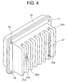
- FIG. 4 there is shown a specific example of the embodiment as described above, which is manufactured as a typical telecommunication device, such as a base station of a personal handyphone system generally attached onto a mast or pole etc.
- the hollow space 17 includes a plurality of vertical channels when the telecommunication device is installed on a mast.
- the integrated circuits 24 In operation of the telecommunication device of Fig. 1, the integrated circuits 24 generate heat based on the operating current. The heat generated in the integrated circuits 24 is transferred to the inner surface of the inner wall 16 of the housing body 11 via the heat conductive sheet 25, and then transferred to the gas refrigerant 19 in the hollow space 17.
- the heat exchange between the gas refrigerant 19 and the outer wall 15 is assisted by the natural convection of the refrigerant 19 in the hollow space 17, wherein a portion of the refrigerant 19 at a higher temperature residing in the vicinities of the outer wall 15 and the inner wall 16 rises upward in the hollow space 17 including the channels, whereas another portion of the refrigerant 19 at a lower temperature residing in the central region between the outer wall 15 and the inner wall 16 falls downward in the hollow space 17.
- the gas refrigerant 19 absorbing the heat generated by the integrated circuits 24 is circulated for heat radiation, which is effected at the outer surface of outer wall 15 of the housing 10.
- the radiation capability is limited by the conductivity of the selected metal or plastic material, exhibiting limited radiation.
- the housing 10 in the telecommunication device of the present embodiment achieves higher heat radiation capability due to the refrigerant 19 cooling the whole area of the radiation fins 21.
- the gas refrigerant 19 in the hollow space 17 expands its volume, thereby raising the inner pressure of the hollow space 17.
- the movable walls 27 are shifted toward outside to the position shown by numeral 27A in Fig. 3.
- the refrigerant 19 in the hollow space 17 reduces its volume, whereby the movable walls 27 are shifted toward inside. If a liquid refrigerant is used, the volume change is not necessary.
Landscapes
- Engineering & Computer Science (AREA)
- Microelectronics & Electronic Packaging (AREA)
- Physics & Mathematics (AREA)
- Thermal Sciences (AREA)
- Cooling Or The Like Of Electrical Apparatus (AREA)
- Moulds For Moulding Plastics Or The Like (AREA)
Applications Claiming Priority (2)
| Application Number | Priority Date | Filing Date | Title |
|---|---|---|---|
| JP2001246940A JP2003060371A (ja) | 2001-08-16 | 2001-08-16 | 通信機器筐体の放熱構造 |
| JP2001246940 | 2001-08-16 |
Publications (2)
| Publication Number | Publication Date |
|---|---|
| EP1284592A2 true EP1284592A2 (de) | 2003-02-19 |
| EP1284592A3 EP1284592A3 (de) | 2005-11-16 |
Family
ID=19076378
Family Applications (1)
| Application Number | Title | Priority Date | Filing Date |
|---|---|---|---|
| EP02018497A Withdrawn EP1284592A3 (de) | 2001-08-16 | 2002-08-16 | Vermittlungseinrichtung mit einem Gehäuse, dessen Wärmeleitfähigkeit verbessert ist |
Country Status (3)
| Country | Link |
|---|---|
| US (1) | US7040383B2 (de) |
| EP (1) | EP1284592A3 (de) |
| JP (1) | JP2003060371A (de) |
Cited By (3)
| Publication number | Priority date | Publication date | Assignee | Title |
|---|---|---|---|---|
| GB2411049A (en) * | 2004-01-23 | 2005-08-17 | Jonathan David Cadd | Specific heat capacity heatsink for electronics |
| EP2337437A2 (de) * | 2009-12-17 | 2011-06-22 | Quixant Limited | Elektronische Anordnung und Gehäuse dafür |
| WO2013000119A1 (en) | 2011-06-28 | 2013-01-03 | Telefonaktiebolaget L M Ericsson (Publ) | Electronic device with heat-dissipating structure |
Families Citing this family (49)
| Publication number | Priority date | Publication date | Assignee | Title |
|---|---|---|---|---|
| JP4325219B2 (ja) * | 2003-02-26 | 2009-09-02 | 日本電気株式会社 | 電子装置の筐体構造とその密閉筐体の内部の気圧調整方法 |
| US7505862B2 (en) * | 2003-03-07 | 2009-03-17 | Salmon Technologies, Llc | Apparatus and method for testing electronic systems |
| EP1538760A1 (de) * | 2003-06-12 | 2005-06-08 | Matsushita Electric Industrial Co., Ltd. | Basisstationsvorrichtung |
| US7408258B2 (en) * | 2003-08-20 | 2008-08-05 | Salmon Technologies, Llc | Interconnection circuit and electronic module utilizing same |
| DK200301577A (da) * | 2003-10-27 | 2005-04-28 | Danfoss Silicon Power Gmbh | Flowfordelingsenhed og köleenhed |
| US20050184376A1 (en) * | 2004-02-19 | 2005-08-25 | Salmon Peter C. | System in package |
| US20050255722A1 (en) * | 2004-05-07 | 2005-11-17 | Salmon Peter C | Micro blade assembly |
| US7254024B2 (en) * | 2004-05-11 | 2007-08-07 | Salmon Peter C | Cooling apparatus and method |
| US7427809B2 (en) * | 2004-12-16 | 2008-09-23 | Salmon Technologies, Llc | Repairable three-dimensional semiconductor subsystem |
| US20070007983A1 (en) * | 2005-01-06 | 2007-01-11 | Salmon Peter C | Semiconductor wafer tester |
| US7077189B1 (en) | 2005-01-21 | 2006-07-18 | Delphi Technologies, Inc. | Liquid cooled thermosiphon with flexible coolant tubes |
| US7506682B2 (en) * | 2005-01-21 | 2009-03-24 | Delphi Technologies, Inc. | Liquid cooled thermosiphon for electronic components |
| US20060162903A1 (en) * | 2005-01-21 | 2006-07-27 | Bhatti Mohinder S | Liquid cooled thermosiphon with flexible partition |
| US20070023904A1 (en) * | 2005-08-01 | 2007-02-01 | Salmon Peter C | Electro-optic interconnection apparatus and method |
| US20070023923A1 (en) * | 2005-08-01 | 2007-02-01 | Salmon Peter C | Flip chip interface including a mixed array of heat bumps and signal bumps |
| US7586747B2 (en) | 2005-08-01 | 2009-09-08 | Salmon Technologies, Llc. | Scalable subsystem architecture having integrated cooling channels |
| US20070023889A1 (en) * | 2005-08-01 | 2007-02-01 | Salmon Peter C | Copper substrate with feedthroughs and interconnection circuits |
| US7408778B2 (en) * | 2006-09-11 | 2008-08-05 | International Business Machines Corporation | Heat sinks for dissipating a thermal load |
| US8016022B2 (en) * | 2006-11-27 | 2011-09-13 | Honeywell International Inc. | Systems and methods for passive thermal management using phase change material |
| US20080302115A1 (en) * | 2007-06-08 | 2008-12-11 | Coda Octopus Group, Inc. | Combined pressure compensator and cooling unit |
| US20100246124A1 (en) * | 2008-07-24 | 2010-09-30 | Strong Daniel | Enclosure for Confining the Released Chemicals of Electrical Devices |
| TWM351389U (en) * | 2008-09-01 | 2009-02-21 | Aopen Inc | Computer enclosure and computer |
| US8081478B1 (en) * | 2008-12-09 | 2011-12-20 | Lockheed Martin Corporation | Fluid cooled electronics module cover |
| JP2010147208A (ja) * | 2008-12-18 | 2010-07-01 | Nec Corp | 電子機器収納容器及び電子機器収納容器の組立方法 |
| JP5195815B2 (ja) * | 2010-05-10 | 2013-05-15 | トヨタ自動車株式会社 | 電気機器冷却装置 |
| US8537540B2 (en) * | 2010-11-02 | 2013-09-17 | Technology Advancement Group, Inc. | Field serviceable CPU module |
| CN102956582A (zh) * | 2011-08-29 | 2013-03-06 | 富准精密工业(深圳)有限公司 | 散热装置 |
| CN102440090A (zh) * | 2011-09-23 | 2012-05-02 | 华为技术有限公司 | 一种浸没式冷却系统和方法 |
| EP2605345B1 (de) * | 2011-12-13 | 2021-04-28 | Alcatel Lucent | Wärmesteuerung von Photonikanordnungen |
| JP2014123620A (ja) * | 2012-12-20 | 2014-07-03 | Kitamura Seisakusho:Kk | 無線機器収容局舎 |
| US11026347B2 (en) * | 2012-12-21 | 2021-06-01 | Smart Embedded Computing, Inc. | Configurable cooling for rugged environments |
| US20140185214A1 (en) * | 2012-12-31 | 2014-07-03 | Zhen Jia | Stacked power module for graphics processing unit |
| KR101497300B1 (ko) * | 2013-02-07 | 2015-02-27 | 박천순 | 천연광물을 이용한 에스엠피에스의 방열구조 |
| US9310139B2 (en) * | 2013-03-15 | 2016-04-12 | Qualcomm Incorporated | Vapor chambers based skin material for smartphones and mobile devices |
| US9912053B2 (en) | 2014-03-17 | 2018-03-06 | Ubiquiti Networks, Inc. | Array antennas having a plurality of directional beams |
| US10164332B2 (en) | 2014-10-14 | 2018-12-25 | Ubiquiti Networks, Inc. | Multi-sector antennas |
| US9721870B2 (en) * | 2014-12-05 | 2017-08-01 | International Business Machines Corporation | Cooling structure for electronic boards |
| US10284268B2 (en) | 2015-02-23 | 2019-05-07 | Ubiquiti Networks, Inc. | Radio apparatuses for long-range communication of radio-frequency information |
| US9761954B2 (en) | 2015-10-09 | 2017-09-12 | Ubiquiti Networks, Inc. | Synchronized multiple-radio antenna systems and methods |
| ITUB20154977A1 (it) | 2015-10-16 | 2017-04-16 | Medical Microinstruments S R L | Strumento medicale e metodo di fabbricazione di detto strumento medicale |
| GB2543790A (en) * | 2015-10-28 | 2017-05-03 | Sustainable Engine Systems Ltd | Pin fin heat exchanger |
| TWM541686U (zh) * | 2016-12-27 | 2017-05-11 | 微星科技股份有限公司 | 電子裝置 |
| JP2018157005A (ja) | 2017-03-16 | 2018-10-04 | 東芝メモリ株式会社 | 電子機器 |
| DE102018222748B4 (de) * | 2018-12-21 | 2023-05-17 | Vitesco Technologies Germany Gmbh | Kühlvorrichtung |
| CN112635418A (zh) * | 2019-10-08 | 2021-04-09 | 全亿大科技(佛山)有限公司 | 液冷散热器 |
| CN214412924U (zh) * | 2020-11-20 | 2021-10-15 | 京东方科技集团股份有限公司 | 一种网络适配器以及终端设备 |
| CN114916160B (zh) | 2021-02-07 | 2025-04-25 | 华为数字能源技术有限公司 | 电源适配器 |
| CN113891620B (zh) * | 2021-09-27 | 2023-05-23 | 联想(北京)有限公司 | 一种散热装置及电子设备 |
| US20250151225A1 (en) * | 2023-11-02 | 2025-05-08 | Channell Commercial Corporation | Vented pedestal housing |
Family Cites Families (41)
| Publication number | Priority date | Publication date | Assignee | Title |
|---|---|---|---|---|
| US3851221A (en) * | 1972-11-30 | 1974-11-26 | P Beaulieu | Integrated circuit package |
| US4009417A (en) * | 1975-01-27 | 1977-02-22 | General Electric Company | Electrical apparatus with heat pipe cooling |
| JPS59127898A (ja) | 1983-01-13 | 1984-07-23 | 三菱電機株式会社 | 電子機器の防湿装置 |
| US4730665A (en) * | 1983-07-14 | 1988-03-15 | Technology Enterprises Company | Apparatus for cooling high-density integrated circuit packages |
| JPS61136549U (de) | 1985-02-14 | 1986-08-25 | ||
| JPH01264296A (ja) | 1988-04-15 | 1989-10-20 | Hiromi Kataoka | 放熱用部品 |
| JPH0218995A (ja) | 1988-07-07 | 1990-01-23 | Fujitsu Ltd | 冷却モジュール |
| JPH0236078U (de) | 1988-08-31 | 1990-03-08 | ||
| JPH0267792A (ja) | 1988-09-01 | 1990-03-07 | Fujitsu Ltd | 浸漬冷却モジュール |
| DE4121534C2 (de) * | 1990-06-30 | 1998-10-08 | Toshiba Kawasaki Kk | Kühlvorrichtung |
| JPH04245499A (ja) | 1991-01-30 | 1992-09-02 | Matsushita Electric Ind Co Ltd | 半導体素子のシールドケース |
| JPH05243771A (ja) | 1992-02-26 | 1993-09-21 | Koufu Nippon Denki Kk | 浸漬dc−dcコンバータの冷却構造 |
| JPH0794881A (ja) | 1993-09-20 | 1995-04-07 | Fujitsu Ltd | 冷媒の流量調節装置 |
| JPH0767231A (ja) | 1993-08-30 | 1995-03-10 | Yazaki Corp | 電気接続箱の放熱構造 |
| US5485671A (en) * | 1993-09-10 | 1996-01-23 | Aavid Laboratories, Inc. | Method of making a two-phase thermal bag component cooler |
| US5704416A (en) * | 1993-09-10 | 1998-01-06 | Aavid Laboratories, Inc. | Two phase component cooler |
| JPH0729499U (ja) | 1993-11-05 | 1995-06-02 | 株式会社イノアックコーポレーション | 高温発熱体のカバー体 |
| US5373417A (en) * | 1994-02-28 | 1994-12-13 | Motorola, Inc. | Liquid-cooled circuit package with micro-bellows for controlling expansion |
| JPH0825400A (ja) | 1994-07-08 | 1996-01-30 | Polyplastics Co | 流体流路を内部に有する成形体および給水装置 |
| US5390077A (en) * | 1994-07-14 | 1995-02-14 | At&T Global Information Solutions Company | Integrated circuit cooling device having internal baffle |
| EP0757886A4 (de) * | 1995-01-25 | 1999-05-06 | Aavid Eng Inc | Thermisches kontrollsystem |
| JPH0917920A (ja) | 1995-06-30 | 1997-01-17 | Riyoosan:Kk | 半導体素子冷却用ヒートシンク |
| DE19545448A1 (de) | 1995-12-06 | 1997-06-12 | Abb Patent Gmbh | Stromrichter-Multifunktionsgehäuse für ein Fahrzeug |
| JPH09207207A (ja) | 1996-01-31 | 1997-08-12 | Kyoraku Co Ltd | ハウジングパネルの製造方法 |
| US5675473A (en) * | 1996-02-23 | 1997-10-07 | Motorola, Inc. | Apparatus and method for shielding an electronic module from electromagnetic radiation |
| US6167948B1 (en) * | 1996-11-18 | 2001-01-02 | Novel Concepts, Inc. | Thin, planar heat spreader |
| JP3207138B2 (ja) | 1997-07-29 | 2001-09-10 | 三菱電機株式会社 | 水蒸発式冷却装置 |
| US6062302A (en) | 1997-09-30 | 2000-05-16 | Lucent Technologies Inc. | Composite heat sink |
| EP0914926B1 (de) * | 1997-11-07 | 2002-09-11 | Rohm And Haas Company | Verfahren und Vorrichtung zum Formen einer Kunststoffplatte |
| US5944093A (en) * | 1997-12-30 | 1999-08-31 | Intel Corporation | Pickup chuck with an integral heat pipe |
| JPH11204952A (ja) | 1998-01-14 | 1999-07-30 | Toyo Electric Mfg Co Ltd | 電気機器収納箱 |
| EP0946085A1 (de) | 1998-03-24 | 1999-09-29 | Lucent Technologies Inc. | Elektronisches Gerät mit Umweltschutz-Aussengehäuse |
| JP2000198388A (ja) | 1998-12-28 | 2000-07-18 | Ichikoh Ind Ltd | ドアミラ―のハウジング |
| JP2000208948A (ja) | 1999-01-08 | 2000-07-28 | Nec Fukushima Ltd | 機器筐体の構造 |
| JP3717708B2 (ja) | 1999-05-27 | 2005-11-16 | 沖電気工業株式会社 | 電子機器の放熱構造 |
| US6490160B2 (en) * | 1999-07-15 | 2002-12-03 | Incep Technologies, Inc. | Vapor chamber with integrated pin array |
| US6410982B1 (en) * | 1999-11-12 | 2002-06-25 | Intel Corporation | Heatpipesink having integrated heat pipe and heat sink |
| JP3570329B2 (ja) | 2000-02-29 | 2004-09-29 | 日本電気株式会社 | 圧力調整機能付密閉筐体 |
| US6367543B1 (en) * | 2000-12-11 | 2002-04-09 | Thermal Corp. | Liquid-cooled heat sink with thermal jacket |
| US6525420B2 (en) * | 2001-01-30 | 2003-02-25 | Thermal Corp. | Semiconductor package with lid heat spreader |
| US20020118511A1 (en) * | 2001-02-28 | 2002-08-29 | Dujari Prateek J. | Heat dissipation device |
-
2001
- 2001-08-16 JP JP2001246940A patent/JP2003060371A/ja active Pending
-
2002
- 2002-08-15 US US10/218,585 patent/US7040383B2/en not_active Expired - Fee Related
- 2002-08-16 EP EP02018497A patent/EP1284592A3/de not_active Withdrawn
Cited By (3)
| Publication number | Priority date | Publication date | Assignee | Title |
|---|---|---|---|---|
| GB2411049A (en) * | 2004-01-23 | 2005-08-17 | Jonathan David Cadd | Specific heat capacity heatsink for electronics |
| EP2337437A2 (de) * | 2009-12-17 | 2011-06-22 | Quixant Limited | Elektronische Anordnung und Gehäuse dafür |
| WO2013000119A1 (en) | 2011-06-28 | 2013-01-03 | Telefonaktiebolaget L M Ericsson (Publ) | Electronic device with heat-dissipating structure |
Also Published As
| Publication number | Publication date |
|---|---|
| EP1284592A3 (de) | 2005-11-16 |
| US20030034148A1 (en) | 2003-02-20 |
| JP2003060371A (ja) | 2003-02-28 |
| US7040383B2 (en) | 2006-05-09 |
Similar Documents
| Publication | Publication Date | Title |
|---|---|---|
| US7040383B2 (en) | Telecommunication device including a housing having improved heat conductivity | |
| EP3096103B1 (de) | Kühlvorrichtung und elektronische vorrichtung | |
| EP1494109B1 (de) | Wärmeableitstruktur für ein Mobilgerät | |
| EP0565366B1 (de) | Kühlungssystem zur Kühlung von elektronischen Vorrichtungen | |
| US5704416A (en) | Two phase component cooler | |
| JP3385482B2 (ja) | 電子機器 | |
| US5587880A (en) | Computer cooling system operable under the force of gravity in first orientation and against the force of gravity in second orientation | |
| US20190335619A1 (en) | Loop heat transfer device with gaseous and liquid working fluid channels separated by partition wall | |
| EP3091321B1 (de) | Kältemittelverteilungsvorrichtung und kühlvorrichtung | |
| US20070133172A1 (en) | Cooling system for computer components | |
| CN215819124U (zh) | 电子器件的散热装置 | |
| US11912190B2 (en) | Refrigerator for vehicle and vehicle | |
| KR102543845B1 (ko) | 전장소자의 방열장치 | |
| US10629460B2 (en) | Circulation cooling and heating device for controlling a temperature of a circulating fluid supplied to a chamber | |
| US20230021186A1 (en) | Heat dissipation device for electronic element | |
| US20050098305A1 (en) | Integrated liquid cooling system for electronic components | |
| WO2022095457A1 (zh) | 电子设备、车载散热系统及车辆 | |
| US20080105404A1 (en) | Heat dissipating system having a heat dissipating cavity body | |
| US20190339021A1 (en) | Joint vapor chamber assembly with vapor chambers connected by extension wick layer | |
| EP1923915A2 (de) | Wärmeableitungssystem mit Hohlkörper zur Wärmeableitung | |
| CN112602232A (zh) | 天线装置的散热装置 | |
| US6980436B2 (en) | Computer cooling system | |
| CN102290388A (zh) | 电控设备、热管散热器及其制作方法 | |
| CN210803944U (zh) | 散热结构及电子装置 | |
| US20030116309A1 (en) | Heat exchanging apparatus and method of manufacture |
Legal Events
| Date | Code | Title | Description |
|---|---|---|---|
| PUAI | Public reference made under article 153(3) epc to a published international application that has entered the european phase |
Free format text: ORIGINAL CODE: 0009012 |
|
| AK | Designated contracting states |
Designated state(s): AT BE BG CH CY CZ DE DK EE ES FI FR GB GR IE IT LI LU MC NL PT SE SK TR |
|
| AX | Request for extension of the european patent |
Extension state: AL LT LV MK RO SI |
|
| PUAL | Search report despatched |
Free format text: ORIGINAL CODE: 0009013 |
|
| AK | Designated contracting states |
Kind code of ref document: A3 Designated state(s): AT BE BG CH CY CZ DE DK EE ES FI FR GB GR IE IT LI LU MC NL PT SE SK TR |
|
| AX | Request for extension of the european patent |
Extension state: AL LT LV MK RO SI |
|
| 17P | Request for examination filed |
Effective date: 20051011 |
|
| AKX | Designation fees paid |
Designated state(s): DE GB |
|
| STAA | Information on the status of an ep patent application or granted ep patent |
Free format text: STATUS: THE APPLICATION IS DEEMED TO BE WITHDRAWN |
|
| 18D | Application deemed to be withdrawn |
Effective date: 20060808 |