EP1284613B1 - Fermeture a sifflet integre - Google Patents
Fermeture a sifflet integre Download PDFInfo
- Publication number
- EP1284613B1 EP1284613B1 EP01926946A EP01926946A EP1284613B1 EP 1284613 B1 EP1284613 B1 EP 1284613B1 EP 01926946 A EP01926946 A EP 01926946A EP 01926946 A EP01926946 A EP 01926946A EP 1284613 B1 EP1284613 B1 EP 1284613B1
- Authority
- EP
- European Patent Office
- Prior art keywords
- whistle
- adjuster
- adjuster according
- strap
- tending
- Prior art date
- Legal status (The legal status is an assumption and is not a legal conclusion. Google has not performed a legal analysis and makes no representation as to the accuracy of the status listed.)
- Expired - Lifetime
Links
Images

Classifications
-
- A—HUMAN NECESSITIES
- A44—HABERDASHERY; JEWELLERY
- A44B—BUTTONS, PINS, BUCKLES, SLIDE FASTENERS, OR THE LIKE
- A44B11/00—Buckles; Similar fasteners for interconnecting straps or the like, e.g. for safety belts
- A44B11/005—Buckles combined with other articles, e.g. with receptacles
-
- A—HUMAN NECESSITIES
- A44—HABERDASHERY; JEWELLERY
- A44B—BUTTONS, PINS, BUCKLES, SLIDE FASTENERS, OR THE LIKE
- A44B11/00—Buckles; Similar fasteners for interconnecting straps or the like, e.g. for safety belts
- A44B11/001—Ornamental buckles
-
- A—HUMAN NECESSITIES
- A44—HABERDASHERY; JEWELLERY
- A44B—BUTTONS, PINS, BUCKLES, SLIDE FASTENERS, OR THE LIKE
- A44B11/00—Buckles; Similar fasteners for interconnecting straps or the like, e.g. for safety belts
- A44B11/25—Buckles; Similar fasteners for interconnecting straps or the like, e.g. for safety belts with two or more separable parts
- A44B11/26—Buckles; Similar fasteners for interconnecting straps or the like, e.g. for safety belts with two or more separable parts with push-button fastenings
- A44B11/266—Buckles; Similar fasteners for interconnecting straps or the like, e.g. for safety belts with two or more separable parts with push-button fastenings with at least one push-button acting parallel to the main plane of the buckle and perpendicularly to the direction of the fastening action
-
- Y—GENERAL TAGGING OF NEW TECHNOLOGICAL DEVELOPMENTS; GENERAL TAGGING OF CROSS-SECTIONAL TECHNOLOGIES SPANNING OVER SEVERAL SECTIONS OF THE IPC; TECHNICAL SUBJECTS COVERED BY FORMER USPC CROSS-REFERENCE ART COLLECTIONS [XRACs] AND DIGESTS
- Y10—TECHNICAL SUBJECTS COVERED BY FORMER USPC
- Y10T—TECHNICAL SUBJECTS COVERED BY FORMER US CLASSIFICATION
- Y10T24/00—Buckles, buttons, clasps, etc.
- Y10T24/40—Buckles
- Y10T24/4086—Looped strap
-
- Y—GENERAL TAGGING OF NEW TECHNOLOGICAL DEVELOPMENTS; GENERAL TAGGING OF CROSS-SECTIONAL TECHNOLOGIES SPANNING OVER SEVERAL SECTIONS OF THE IPC; TECHNICAL SUBJECTS COVERED BY FORMER USPC CROSS-REFERENCE ART COLLECTIONS [XRACs] AND DIGESTS
- Y10—TECHNICAL SUBJECTS COVERED BY FORMER USPC
- Y10T—TECHNICAL SUBJECTS COVERED BY FORMER US CLASSIFICATION
- Y10T24/00—Buckles, buttons, clasps, etc.
- Y10T24/40—Buckles
- Y10T24/4088—One-piece
Definitions
- This invention relates to a device to be used for tending straps and also to be used as a whistle. More particularly, this invention relates to a device for tending straps with a whistle integrated within the device where both the whistling and strap-tending functions are independently operable.
- the buckle on a typical belt is maybe the most recognizable, but fasteners with similar functions encompass a wide range of designs and related functions, see U.S. Patent 5,794,316 for example.
- the "tending strap” function is intended to encompass the various functions performed by devices that are attached to straps, or more specifically to belts, webbing, or cords, and that work to secure the straps under tension (a buckle or webbing adjuster for example), confine them to a particular area (a slider), or limit movement of other items along the strap (a cord lock).
- the articles utilizing these designs are ubiquitous where one finds hikers, boaters, campers, climbers, and other persons employing similar gear.
- Whistles in general take many forms, for examples see U.S. patents 5,546,887 and 5,507,246 . Such whistles undeniably perform the necessary function if they are available. But such whistles are often not available for any number of reasons. A solitary whistle is not an item that most would habitually carry. Therefore a potential user would probably need a reason to include a whistle in the gear for that day. Most of the obvious reasons are related to emergencies and most people do not anticipate having emergencies. This would make a whistle a low priority item on anyone's packing list. And because emergencies are notably rare, the whistle would in fact generally be just another item cluttering up a purse, key-chain, or related devices. This limited need makes it easy and understandable to simply forget to carry a whistle even should one think it a good idea in general.
- Buckles have been proposed incorporating tools such as a whistle, however the design has been unsatisfactory and has not gained wide spread acceptance.
- U.S. Patent Nos. 3,885,250 and 3,903,547 disclose a buckle with a prong that may be fashioned into a whistle. While specific details of how such a whistle might be formed are not disclosed, the general arrangement is not satisfactory because, being on a prong, such a whistle would be hidden and even if known, use would require disengagement of the retained strap or belt. Additionally, the strap must be large enough to house the whistle. This requirement prevents incorporation of a whistle where the strap is of small cross-section because the prong must be accommodated within either a thick strap or two layers of strap.
- the strap must be specially manufactured to accept the flange, increasing manufacturing costs and reducing the application of the buckle because it must necessarily be part of a matched set to function.
- the prong is rigid and extends into the strap the areas where the buckle can be located are limited to relatively flat locations that extend the length of the prong and buckle.
- GB 2,277,351 discusses a draw-cord grip, such as those used for securing draw-cords on waterproof and leisure clothing, incorporating a whistle, through the body of which a cord is provided.
- the preferred embodiments of the present invention combine the function of a whistle with that of a device for tending straps, cords, belts, or webbing of various shapes and sizes.
- the whistle is combined with the strap-tending device in a manner that allows the whistle to be used even when the device is tending the straps as designed.
- the placement of the whistle is preferably transverse to that direction to facilitate access to the whistle, decrease device dimensions, and improve its manufacturability.
- the strap-tending functions of the preferred embodiments include: a two-piece side release buckle with the whistle incorporated in the female half and the strap adjusting mechanism in the male half; a single piece strap adjuster with the whistle located opposite the anchor bars and slots from the extension designed to facilitate releasing tension; a cord lock with the whistle integrated into the barrel; and a slider with the whistle integrated to one side of the slots designed to engage the straps.
- the whistle is accessible and functional with the intended strap or straps in place and the device performing its intended strap-tending function.
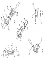
- Female body 11 comprises the female half of a side release buckle with an integral whistle portion 16 that is itself comprised of chamber 13 (seen in cross-section along line A-A in FIG. 5 ), exit hole (or sharp-edged lip) 15, end cap 12, and entry hole 14.
- Anchor bar 17 is located adjacent to chamber 13 and defines slot 20 for a strap to pass through.
- Chamber 13 is transverse to the direction of strap tension as shown in FIG. 2 which depicts strap 18 anchored to female body 11 using strap anchor bar 17 (not visible). Entry hole 14 is located opposite exit hole 15 from end cap 12. Notice that both entry hole 14 and exit hole 15 are accessible when strap 18 is anchored. This allows the whistle to be activated with strap 18 attached.
- Male body 19 comprises the male half of the side release buckle and is shown in FIG. 2 in position for coupling to female body 11.
- Male body 19 also comprises strap anchor bar 17 and slots 20 and 22 used for slidably securing strap 24 as shown in FIG. 3 leaving free end 26 available for further tension adjustment. Strap 24 is attached by threading it up through slot 20, around anchor bar 17, down through slot 22 and out past male body 19. Once past male body 19 strap 24 is referred to as free end 26 to facilitate discussing the adjustment of strap 24. Friction between strap 24, free end 26, anchor bar 17 and male body 19 work to keep strap 24 attached to male body 19.
- both entry hole 14 and exit hole 15 are accessible when strap 24 and free end 26 are secured. Notice also that holes 14 and 15 are accessible when bodies 11 and 19 are coupled. Since straps 18 and 24, free end 26, and the coupling of bodies 11 and 19 do not hinder access to holes 14 and 15 the whistle is operable independently from the function of the device.
- FIGS. 4 and 5 further depict the side release buckle and whistle embodiment of the invention.
- female body 11 is a single molded item incorporating entry hole 14, exit hole 15, and the substantial majority of chamber 13.
- Chamber 13 is completed and the whistle made functional with the addition of end cap 12.
- This preferred embodiment uses annular snap fit geometry to connect end cap 12 to female body 11.
- All the elements of the whistle could be incorporated in male body 19, rather than female body 11, but oriented in a similar way between slot 20 and the male connecting means of the buckle.
- Whistle operation is effectuated by blowing air into entry hole 14. When exiting chamber 13 this air flows past the lip of exit hole 15. The combination of the air flow, lip, and chamber combine to create the whistle sound.
- FIGS. 6 and 7 An alternative preferred embodiment of the invention is depicted in FIGS. 6 and 7 .
- This embodiment is termed a combination webbing length adjuster and whistle.
- the whistle elements and function are as described in FIGS. 4-5 , but the two-piece nature of the buckle and whistle combination has been replaced by a one piece adjuster body 28.
- Adjuster body 28 functions to adjust webbing or strap 18 and 24 tension in a manner similar to the combination of male body 19 with female body 11 except that adjuster body 28 lacks the ability to quickly release tension that is supplied by the disconnect feature of the combination.
- FIG. 7 again shows how strap 18 is attached to anchor bar 17 and strap 24 is adjusted by routing it through slot 20, around anchor bar 17, and back through slot 22. Free end 26 is then used to adjust strap 24.
- Tension on strap 24 is released by lifting adjuster body 28 away from strap 24. Tension on strap 24 is increased by simply pulling on free end 26.
- straps 18 and 24 can be ends of the same strap or ends from two different straps depending on the intended function of the device. Note that as shown in FIGS. 6 and 7 , straps 18 and 24 and free end 26 do not obstruct entry hole 14 and exit hole 15, making the whistle operational even when the device is also tending straps 18 and 24.
- FIGS. 8 and 9 A cord lock and whistle combination is depicted in FIGS. 8 and 9 for background understanding.
- the release button 30 and compression spring 32 are slidably engaged inside lock body 34 and retained by cord 36 passing through the cord hole 38 as shown in FIG. 9 along line C-C from FIG. 8 .
- Cord hole 38 passes through both lock body 34 and release button 30.
- Tension in cord 36 is adjusted by depressing release button 30 and sliding lock body 34 in the appropriate direction along cord 36.
- Cord 36 is bound by lock body 34 by the deformation of cord 36 and friction between cord 36, lock body 34, and release button 30. The deformation and friction are caused when compression spring 32 forces release button 30 against cord 36, which is in turn forced against lock body 34.
- Chamber 13 is defined by lock body 34, once again transverse to the direction of cord tension.
- the chamber is completed by release button 30, which fulfills the function previously performed by end cap 12 of the other preferred embodiments. Note again that cord 36 does not obstruct entry hole 14 or exit hole 15 making the whistle operational even
- FIGS. 10 and 11 An additional preferred embodiment is the slider and whistle combination of FIGS. 10 and 11 .
- the slider device is designed to permit two or more pieces of webbing to be slideably engaged relative to one another.
- FIG. 11 depicts the routing as seen along line D-D from FIG. 10 where slider body 40 is shown engaging strap 24 and free end 26 after they have passed through adjuster body 28 (not shown), or side release buckle 3 (not shown).
- the geometry of slots 20 and 22 and anchor bar 17 is different in this embodiment from that in side release buckle male body 19 or adjuster body 28 due to the different frictional requirements of the slider.
- the routing of strap 24 and free end 26 from another strap-tending device highlights one desirable aspect of the invention where multiple whistles can be located on a single item of gear without increasing the number of parts needed to make the piece of gear functional. Incorporating whistles into all strap-tending elements would make accessing a whistle much easier and potentially decrease the manufacturing costs associated with adding a whistle to any one device.
Landscapes
- Automotive Seat Belt Assembly (AREA)
- Buckles (AREA)
- Package Frames And Binding Bands (AREA)
Abstract
Claims (23)
- Ajusteur de longueur de sangle comprenant un sifflet intégré (16) comprenant : un corps (11, 19, 28, 40) prévu pour tendre au moins une sangle (18, 24) orientée dans une première direction, et un sifflet (16) intégré dans ledit corps, ledit sifflet (16) comprenant un trou d'entrée (14) et un trou de sortie (15) formés dans ledit corps, de telle sorte que le tensionnement d'au moins une sangle n'entrave pas le fonctionnement dudit sifflet.
- Ajusteur selon la revendication 1, comprenant au moins une fente (20, 22) pour tendre au moins une sangle (18, 24) orientée dans une première direction.
- Ajusteur selon la revendication 2, dans lequel le corps comprend des organes latéraux réunis par une barre d'ancrage (17) pour définir l'au moins une fente (20, 22).
- Ajusteur selon l'une quelconque des revendications 1, 2 ou 3, dans lequel ledit sifflet (16) est positionné dans ledit corps (11, 19, 28, 40) de telle sorte qu'il puisse être utilisé depuis une deuxième direction approximativement transversale à ladite première direction.
- Ajusteur selon l'une quelconque des revendications 1 à 4, comprenant en outre un moyen de bouclage (11, 19).
- Ajusteur selon la revendication 2 ou selon les revendications 3 ou 4, lorsqu'elles dépendent de la revendication 2, comprenant en outre un moyen de bouclage (11, 19), ledit moyen de bouclage (11, 19) étant opposé à ladite au moins une fente (20, 22) pour fournir un bouclage de l'ajusteur.
- Ajusteur selon la revendication 5 ou 6, dans lequel ledit moyen de bouclage (11, 19) comprend un moyen de connexion mâle (19) d'une boucle à libération latérale.
- Ajusteur selon la revendication 5 ou 6, dans lequel ledit moyen de bouclage (11, 19) comprend un moyen de connexion femelle (11) d'une boucle à libération latérale.
- Ajusteur selon la revendication 1, dans lequel l'ajusteur comprend une première, deuxième et troisième fente (20, 22), lesdites première, deuxième et troisième fentes (20, 22) étant configurées pour tendre au moins une sangle (18, 24).
- Ajusteur selon l'une quelconque des revendications précédentes, dans lequel lesdits trous d'entrée/de sortie (14, 15) sont disposés sur ledit corps (11, 19, 28, 40) de manière à être au moins substantiellement libres de ladite au moins une fente (20, 22) dans l'état tendu.
- Ajusteur selon la revendication 10, dans lequel ledit trou d'entrée (14) et ledit trou de sortie (15) sont situés le long d'une ligne, ladite ligne étant approximativement transversale à ladite première direction.
- Ajusteur selon la revendication 1, dans lequel l'ajusteur comprend au moins deux fentes (20, 22) ; le trou d'entrée (14) et le trou de sortie (15) communiquant avec une chambre à sifflet (13) intégrée dans ledit corps (11, 19, 28, 40), avec lesdites au moins deux fentes (20, 22) d'un côté de ladite chambre à sifflet (13).
- Ajusteur selon la revendication 12, dans lequel ledit corps (11, 19, 28, 40) comprend en outre une portion d'ajusteur (28), lesdites au moins deux fentes (20, 22) étant entre la portion d'ajusteur (28) et ladite chambre à sifflet (13).
- Ajusteur selon l'une quelconque des revendications précédentes, dans lequel le sifflet (16) comprend en outre un capuchon de bout (12) pourvu du sifflet intégré (16).
- Ajusteur de longueur de sangle comprenant un sifflet intégré (16) selon la revendication 1, dans lequel le sifflet (16) est formé intégralement avec ledit corps (11, 19, 28, 40) de telle sorte que ledit corps (11, 19, 28, 40) et ledit sifflet (16) soient formés sous forme d'un composant moulé unique, ledit sifflet (16) comportant un trou d'entrée d'air (14) et un trou de sortie d'air (15), l'ajusteur comprenant en outre un capuchon de bout (12) avec le sifflet intégré (16).
- Ajusteur selon la revendication 15, dans lequel ledit corps (11, 19, 28, 40) comprend au moins une fente (20, 22).
- Ajusteur selon la revendication 16, dans lequel ledit sifflet (16) constitue une extrémité dudit corps (11, 19, 28, 40).
- Ajusteur selon la revendication 15, comprenant en outre un moyen de bouclage (11, 19) formé intégralement avec ledit corps (11, 19, 28, 40), de telle sorte que ledit corps (11, 19, 28, 40), ledit sifflet (16) et ledit moyen de bouclage (11, 19) soient formés sous forme d'une unité moulée unique.
- Ajusteur selon la revendication 18, dans lequel ledit moyen de bouclage (11, 19) comprend un moyen de connexion mâle (19) d'une boucle à libération latérale.
- Ajusteur selon la revendication 18, dans lequel ledit moyen de bouclage (11, 19) comprend un moyen de connexion femelle (11) d'une boucle à libération latérale.
- Ajusteur selon la revendication 15, dans lequel ledit sifflet (16) est positionné dans ledit corps (11, 19, 28, 40) de telle sorte qu'il puisse être utilisé depuis une deuxième direction approximativement transversale à ladite première direction.
- Ajusteur selon la revendication 21, dans lequel ledit sifflet (16) comporte en outre une chambre (13) qui s'étend entre et communique avec lesdits trous d'entrée d'air (14) et de sortie d'air (15).
- Ajusteur selon la revendication 15, dans lequel ledit capuchon de bout (12) est adapté pour être encliqueté sur ledit sifflet (16).
Applications Claiming Priority (3)
| Application Number | Priority Date | Filing Date | Title |
|---|---|---|---|
| US19658200P | 2000-04-13 | 2000-04-13 | |
| US196582P | 2000-04-13 | ||
| PCT/US2001/012058 WO2001078545A1 (fr) | 2000-04-13 | 2001-04-12 | Fermeture a sifflet integre |
Publications (3)
| Publication Number | Publication Date |
|---|---|
| EP1284613A1 EP1284613A1 (fr) | 2003-02-26 |
| EP1284613A4 EP1284613A4 (fr) | 2007-01-17 |
| EP1284613B1 true EP1284613B1 (fr) | 2010-11-03 |
Family
ID=22725964
Family Applications (1)
| Application Number | Title | Priority Date | Filing Date |
|---|---|---|---|
| EP01926946A Expired - Lifetime EP1284613B1 (fr) | 2000-04-13 | 2001-04-12 | Fermeture a sifflet integre |
Country Status (7)
| Country | Link |
|---|---|
| US (1) | US6668428B2 (fr) |
| EP (1) | EP1284613B1 (fr) |
| AU (1) | AU2001253446A1 (fr) |
| CA (1) | CA2405400C (fr) |
| DE (1) | DE60143387D1 (fr) |
| ES (1) | ES2355807T3 (fr) |
| WO (1) | WO2001078545A1 (fr) |
Families Citing this family (32)
| Publication number | Priority date | Publication date | Assignee | Title |
|---|---|---|---|---|
| CA2522475A1 (fr) * | 2004-10-05 | 2006-04-05 | Sportcraft, Ltd. | Sifflet et chronometre combines montes sur un anneau |
| US8105175B2 (en) | 2006-11-27 | 2012-01-31 | Acushnet Company | Golf club having removable sole weight using custom and interchangeable panels |
| US7758452B2 (en) | 2008-11-03 | 2010-07-20 | Acushnet Company | Golf club having removable sole weight |
| FR2926959B1 (fr) * | 2008-02-06 | 2010-03-26 | Zedel | Element d'attache equipe d'un sifflet |
| KR100995471B1 (ko) * | 2008-07-15 | 2010-11-18 | 백지숙 | 휘슬이 장착된 버클 |
| US8434429B2 (en) * | 2008-08-06 | 2013-05-07 | Thomas Andrew Moeller | Pet leash assemblies, pet collar assemblies, and methods of using the same |
| CN101721017B (zh) * | 2008-10-13 | 2012-10-03 | 白智淑 | 装有哨子的搭扣 |
| DE102008037455A1 (de) | 2008-10-16 | 2010-05-12 | Jisook Paik | Mit einer Pfeife versehene Schnalle |
| US8388465B2 (en) * | 2008-11-03 | 2013-03-05 | Acushnet Company | Golf club having removeable sole weight |
| US8312602B2 (en) * | 2008-11-07 | 2012-11-20 | Jisook Paik | Buckle equipped with a whistle |
| US8162709B2 (en) | 2010-08-31 | 2012-04-24 | Pelican International Inc. | Paddle having a lever for generating sound |
| JP5852801B2 (ja) * | 2011-07-25 | 2016-02-03 | 株式会社ニフコ | バックル |
| US20130224667A1 (en) * | 2012-02-24 | 2013-08-29 | Dale Roybal | Survival Buckle |
| AU2012324023A1 (en) * | 2012-08-02 | 2014-02-20 | Sea To Summit Pty Ltd | Field replaceable buckle with reinstallable cross bar |
| US9396716B2 (en) * | 2012-12-19 | 2016-07-19 | Illinois Tool Works Inc. | Whistle assembly |
| USD740101S1 (en) * | 2013-01-31 | 2015-10-06 | Stout Stuff, Llc | Bone shaped slide lock |
| WO2014124016A1 (fr) * | 2013-02-06 | 2014-08-14 | Illinois Tool Works Inc. | Dispositif de fixation de bande à allumoir intégré |
| US9305535B2 (en) | 2013-05-24 | 2016-04-05 | Motorola Solutions, Inc. | Safety alert apparatus for a portable communication device |
| US10123590B2 (en) | 2013-07-10 | 2018-11-13 | Illinois Tool Works Inc. | System and assembly for securing a buckle housing to a component |
| CN104287321A (zh) * | 2013-07-15 | 2015-01-21 | 上海柏拉斯运动用品配件有限公司 | 带口哨的扣具 |
| US20160021984A1 (en) * | 2014-07-28 | 2016-01-28 | Siya, Inc. | Multi-Function Buckle |
| US10085518B2 (en) * | 2014-12-12 | 2018-10-02 | Joseph Flaherty | Boot top opening covers |
| US10219587B1 (en) | 2017-09-05 | 2019-03-05 | Duraflex Hong Kong Limited | Attachment system with a connected article |
| KR101990908B1 (ko) * | 2018-01-04 | 2019-06-20 | 주식회사 우진프라스틱 | 휘슬이 장착된 버클 |
| US12064016B2 (en) * | 2019-01-18 | 2024-08-20 | Outdoor Element, Llc | Buckle assembly with sharpening tool |
| US11089842B2 (en) * | 2019-12-06 | 2021-08-17 | Illinois Tool Works Inc. | Buckle with whistle |
| USD945313S1 (en) | 2020-02-21 | 2022-03-08 | Illinois Tool Works Inc. | Buckle |
| WO2022168280A1 (fr) * | 2021-02-05 | 2022-08-11 | Ykk株式会社 | Accessoire de ruban |
| USD1018371S1 (en) | 2021-10-05 | 2024-03-19 | Illinois Tool Works Inc. | Buckle |
| US20230129408A1 (en) * | 2021-10-22 | 2023-04-27 | John Carl Rasmussen | Aglet Whistle |
| USD1115296S1 (en) | 2022-10-18 | 2026-03-03 | John Carl Rasmussen | Aglet |
| CN116393573B (zh) * | 2023-06-08 | 2023-08-15 | 凌云吉恩斯科技有限公司 | 一种管材制备用防位移的热冲压装置 |
Family Cites Families (38)
| Publication number | Priority date | Publication date | Assignee | Title |
|---|---|---|---|---|
| US1346702A (en) * | 1919-10-10 | 1920-07-13 | George T Colter | Brassiere-hook |
| US3774572A (en) * | 1972-06-21 | 1973-11-27 | R Borraccio | Snow skiing training aid |
| US3885250A (en) | 1974-08-08 | 1975-05-27 | Barry Schiller | Releasable loop belt |
| US3903547A (en) | 1974-08-08 | 1975-09-09 | Barry Schiller | Removable buckle belt |
| US4067290A (en) | 1977-02-10 | 1978-01-10 | Hartley Allen W | Purse theft alarm |
| US4359961A (en) * | 1979-10-22 | 1982-11-23 | Seron Manufacturing Company | Plastic whistle |
| US4553926A (en) * | 1983-06-30 | 1985-11-19 | Serge Crespy | Holder combined with instrument |
| US4709651A (en) * | 1985-08-14 | 1987-12-01 | W.A. Deutsher Proprietary Limited | Whistle |
| USD298841S (en) | 1985-11-19 | 1988-12-06 | Green Douglas L | Whistle |
| CA1275645C (fr) * | 1986-09-19 | 1990-10-30 | Karl F. Mrazek | Dispositif de traction sur corde |
| FR2609641A1 (fr) * | 1987-01-14 | 1988-07-22 | Canecaude Emmanuel De | Objet de divertissement emettant un son inhabituel quand il est manipule |
| USD302398S (en) | 1987-01-20 | 1989-07-25 | Medina Christopher J | Whistle |
| US4893580A (en) | 1987-04-20 | 1990-01-16 | Joseph Jr Alan W | Scuba whistle |
| US4852510A (en) | 1987-04-20 | 1989-08-01 | Alan W. Joseph, Jr. | Scuba whistle |
| US4821670A (en) | 1987-08-07 | 1989-04-18 | Fortron Inc. | Whistle |
| US5002006A (en) * | 1990-07-20 | 1991-03-26 | Ehrenreich Harriet K | Combined safety whistle with article holding means |
| JPH04197303A (ja) * | 1990-11-29 | 1992-07-16 | Asahi Optical Co Ltd | ストラップのバックル |
| US5312082A (en) | 1993-03-29 | 1994-05-17 | Chang Shih Ho | Clipboard having a whistle integrally formed therewith |
| GB2277351A (en) | 1993-04-20 | 1994-10-26 | Mark Glyn Hoyle | Improvements in draw-cord grips |
| KR960003645Y1 (ko) * | 1993-10-22 | 1996-05-04 | 한흥엽 | 모자 부착용 착, 탈식 소리기구 |
| USD350908S (en) | 1994-02-14 | 1994-09-27 | Elias Tamez | Whistle |
| US5546887A (en) | 1994-04-07 | 1996-08-20 | Cameron; Robert W. | Emergency whistle |
| USD369627S (en) | 1994-06-13 | 1996-05-07 | Albert Thor | Combined exercie stick and whistle |
| US5495820A (en) * | 1994-10-04 | 1996-03-05 | Seron Manufacturing Company | Whistle with tone changing rotator |
| US5507246A (en) | 1994-11-07 | 1996-04-16 | Rand, Jr.; David | Visible signaling sports whistle |
| JPH0922603A (ja) * | 1995-07-05 | 1997-01-21 | Suzushiyou Trading:Kk | 笛付懐中電灯 |
| USD381936S (en) | 1995-09-19 | 1997-08-05 | National Molding Corp. | Side-release buckle |
| US5794316A (en) | 1996-06-24 | 1998-08-18 | National Molding Corp. | Side-release buckle having improved locking feature |
| US5780149A (en) * | 1996-09-13 | 1998-07-14 | Libbey-Ownes-Ford Co. | Glass article having a solar control coating |
| JPH1089684A (ja) * | 1996-09-17 | 1998-04-10 | Kunio Horikoshi | 箱型笛付ライター |
| USD385819S (en) | 1996-09-24 | 1997-11-04 | Ming-Chang Chen | Whistle |
| US5845376A (en) | 1997-05-12 | 1998-12-08 | Tung; Chen Chang | Side release buckle |
| TW386368U (en) * | 1998-06-03 | 2000-04-01 | Chuan Ching Mechanical Ind Co | Four-function key chain |
| USD405725S (en) | 1998-07-14 | 1999-02-16 | National Molding Corporation | Female buckle portion |
| USD409939S (en) | 1998-07-21 | 1999-05-18 | J. Hudson & Co. (Whistles) Ltd. | Whistle |
| US6357128B1 (en) * | 1998-07-27 | 2002-03-19 | The Brunton Company | Low profile compass with removable protective cover and magnetic bull's eye alignment system |
| JP2001125575A (ja) * | 1999-10-26 | 2001-05-11 | Unimekkusu Kk | 救命笛 |
| US6416379B1 (en) * | 2000-04-27 | 2002-07-09 | J. Hudson & Co. (Whistles) Ltd. | Whistle |
-
2001
- 2001-04-12 EP EP01926946A patent/EP1284613B1/fr not_active Expired - Lifetime
- 2001-04-12 CA CA002405400A patent/CA2405400C/fr not_active Expired - Lifetime
- 2001-04-12 ES ES01926946T patent/ES2355807T3/es not_active Expired - Lifetime
- 2001-04-12 WO PCT/US2001/012058 patent/WO2001078545A1/fr not_active Ceased
- 2001-04-12 AU AU2001253446A patent/AU2001253446A1/en not_active Abandoned
- 2001-04-12 US US09/834,588 patent/US6668428B2/en not_active Expired - Lifetime
- 2001-04-12 DE DE60143387T patent/DE60143387D1/de not_active Expired - Lifetime
Also Published As
| Publication number | Publication date |
|---|---|
| WO2001078545A1 (fr) | 2001-10-25 |
| DE60143387D1 (de) | 2010-12-16 |
| CA2405400A1 (fr) | 2001-10-25 |
| ES2355807T3 (es) | 2011-03-31 |
| US6668428B2 (en) | 2003-12-30 |
| CA2405400C (fr) | 2009-03-17 |
| AU2001253446A1 (en) | 2001-10-30 |
| EP1284613A1 (fr) | 2003-02-26 |
| US20020029440A1 (en) | 2002-03-14 |
| EP1284613A4 (fr) | 2007-01-17 |
Similar Documents
| Publication | Publication Date | Title |
|---|---|---|
| EP1284613B1 (fr) | Fermeture a sifflet integre | |
| US6393677B1 (en) | Five-way buckle | |
| US4932362A (en) | One finger quick release animal collar | |
| US6851160B2 (en) | Quick release detachable buckle | |
| US7350277B1 (en) | Buckle for safety equipment | |
| US7971908B2 (en) | Guide assembly for a safety belt | |
| US20110314866A1 (en) | Personal Ornament | |
| US20100263171A1 (en) | Device for coupling strap and subordinate item | |
| US7591510B1 (en) | Highly adjustable safety belt for child restraint | |
| US6363590B1 (en) | Safety buckle with buffer means | |
| EP4374731A1 (fr) | Boucle avec sifflet | |
| CN119138692A (zh) | 磁性搭扣 | |
| US3336641A (en) | Buckle structure | |
| US5778453A (en) | Necktie | |
| JP5122150B2 (ja) | 紐留め具 | |
| US7114223B2 (en) | Covered zipper pull assembly | |
| WO2021255564A1 (fr) | Boucle à libération rapide et harnais la comprenant | |
| US5797171A (en) | Buckleless belt | |
| JP3049501B1 (ja) | 長さ調節を可能にした装身具 | |
| US6237826B1 (en) | Safety side-release belt buckle | |
| US6324733B1 (en) | Adjustable, quick release clasp | |
| US20060196020A1 (en) | Seatbeltlock, a controlled release seat belt buckle cover for law enforcement | |
| KR200232825Y1 (ko) | 혁대 장착용 착용대 | |
| WO2001024656A1 (fr) | Ensemble de fixation pour dispositifs de telecommunications personnels | |
| US20060124389A1 (en) | Fall-arresting safety harness with an improved buckle |
Legal Events
| Date | Code | Title | Description |
|---|---|---|---|
| PUAI | Public reference made under article 153(3) epc to a published international application that has entered the european phase |
Free format text: ORIGINAL CODE: 0009012 |
|
| 17P | Request for examination filed |
Effective date: 20021111 |
|
| AK | Designated contracting states |
Kind code of ref document: A1 Designated state(s): AT BE CH CY DE DK ES FI FR GB GR IE IT LI LU MC NL PT SE TR |
|
| AX | Request for extension of the european patent |
Extension state: AL LT LV MK RO SI |
|
| RAP1 | Party data changed (applicant data changed or rights of an application transferred) |
Owner name: ILLINOIS TOOL WORKS INC. |
|
| RIN1 | Information on inventor provided before grant (corrected) |
Inventor name: ILLINOIS TOOL WORKS INC. |
|
| RBV | Designated contracting states (corrected) |
Designated state(s): DE ES FR GB GR IT |
|
| A4 | Supplementary search report drawn up and despatched |
Effective date: 20061218 |
|
| 17Q | First examination report despatched |
Effective date: 20080513 |
|
| GRAP | Despatch of communication of intention to grant a patent |
Free format text: ORIGINAL CODE: EPIDOSNIGR1 |
|
| GRAS | Grant fee paid |
Free format text: ORIGINAL CODE: EPIDOSNIGR3 |
|
| GRAA | (expected) grant |
Free format text: ORIGINAL CODE: 0009210 |
|
| AK | Designated contracting states |
Kind code of ref document: B1 Designated state(s): DE ES FR GB GR IT |
|
| REG | Reference to a national code |
Ref country code: GB Ref legal event code: FG4D |
|
| REF | Corresponds to: |
Ref document number: 60143387 Country of ref document: DE Date of ref document: 20101216 Kind code of ref document: P |
|
| REG | Reference to a national code |
Ref country code: ES Ref legal event code: FG2A Ref document number: 2355807 Country of ref document: ES Kind code of ref document: T3 Effective date: 20110331 |
|
| PG25 | Lapsed in a contracting state [announced via postgrant information from national office to epo] |
Ref country code: GR Free format text: LAPSE BECAUSE OF FAILURE TO SUBMIT A TRANSLATION OF THE DESCRIPTION OR TO PAY THE FEE WITHIN THE PRESCRIBED TIME-LIMIT Effective date: 20110204 |
|
| PLBE | No opposition filed within time limit |
Free format text: ORIGINAL CODE: 0009261 |
|
| STAA | Information on the status of an ep patent application or granted ep patent |
Free format text: STATUS: NO OPPOSITION FILED WITHIN TIME LIMIT |
|
| 26N | No opposition filed |
Effective date: 20110804 |
|
| REG | Reference to a national code |
Ref country code: DE Ref legal event code: R097 Ref document number: 60143387 Country of ref document: DE Effective date: 20110804 |
|
| REG | Reference to a national code |
Ref country code: FR Ref legal event code: PLFP Year of fee payment: 16 |
|
| REG | Reference to a national code |
Ref country code: FR Ref legal event code: PLFP Year of fee payment: 17 |
|
| REG | Reference to a national code |
Ref country code: FR Ref legal event code: PLFP Year of fee payment: 18 |
|
| PGFP | Annual fee paid to national office [announced via postgrant information from national office to epo] |
Ref country code: ES Payment date: 20200504 Year of fee payment: 20 Ref country code: DE Payment date: 20200429 Year of fee payment: 20 Ref country code: FR Payment date: 20200427 Year of fee payment: 20 |
|
| PGFP | Annual fee paid to national office [announced via postgrant information from national office to epo] |
Ref country code: GB Payment date: 20200427 Year of fee payment: 20 Ref country code: IT Payment date: 20200423 Year of fee payment: 20 |
|
| REG | Reference to a national code |
Ref country code: DE Ref legal event code: R071 Ref document number: 60143387 Country of ref document: DE |
|
| REG | Reference to a national code |
Ref country code: GB Ref legal event code: PE20 Expiry date: 20210411 |
|
| REG | Reference to a national code |
Ref country code: ES Ref legal event code: FD2A Effective date: 20210726 |
|
| PG25 | Lapsed in a contracting state [announced via postgrant information from national office to epo] |
Ref country code: GB Free format text: LAPSE BECAUSE OF EXPIRATION OF PROTECTION Effective date: 20210411 |
|
| PG25 | Lapsed in a contracting state [announced via postgrant information from national office to epo] |
Ref country code: ES Free format text: LAPSE BECAUSE OF EXPIRATION OF PROTECTION Effective date: 20210413 |