EP1284839B1 - Usinage au laser de materiaux - Google Patents
Usinage au laser de materiaux Download PDFInfo
- Publication number
- EP1284839B1 EP1284839B1 EP01943283A EP01943283A EP1284839B1 EP 1284839 B1 EP1284839 B1 EP 1284839B1 EP 01943283 A EP01943283 A EP 01943283A EP 01943283 A EP01943283 A EP 01943283A EP 1284839 B1 EP1284839 B1 EP 1284839B1
- Authority
- EP
- European Patent Office
- Prior art keywords
- laser pulses
- pulses
- laser
- sequence
- pulse
- Prior art date
- Legal status (The legal status is an assumption and is not a legal conclusion. Google has not performed a legal analysis and makes no representation as to the accuracy of the status listed.)
- Expired - Lifetime
Links
Images

Classifications
-
- B—PERFORMING OPERATIONS; TRANSPORTING
- B23—MACHINE TOOLS; METAL-WORKING NOT OTHERWISE PROVIDED FOR
- B23K—SOLDERING OR UNSOLDERING; WELDING; CLADDING OR PLATING BY SOLDERING OR WELDING; CUTTING BY APPLYING HEAT LOCALLY, e.g. FLAME CUTTING; WORKING BY LASER BEAM
- B23K26/00—Working by laser beam, e.g. welding, cutting or boring
- B23K26/02—Positioning or observing the workpiece, e.g. with respect to the point of impact; Aligning, aiming or focusing the laser beam
- B23K26/03—Observing, e.g. monitoring, the workpiece
-
- B—PERFORMING OPERATIONS; TRANSPORTING
- B23—MACHINE TOOLS; METAL-WORKING NOT OTHERWISE PROVIDED FOR
- B23K—SOLDERING OR UNSOLDERING; WELDING; CLADDING OR PLATING BY SOLDERING OR WELDING; CUTTING BY APPLYING HEAT LOCALLY, e.g. FLAME CUTTING; WORKING BY LASER BEAM
- B23K26/00—Working by laser beam, e.g. welding, cutting or boring
- B23K26/02—Positioning or observing the workpiece, e.g. with respect to the point of impact; Aligning, aiming or focusing the laser beam
- B23K26/06—Shaping the laser beam, e.g. by masks or multi-focusing
- B23K26/062—Shaping the laser beam, e.g. by masks or multi-focusing by direct control of the laser beam
- B23K26/0622—Shaping the laser beam, e.g. by masks or multi-focusing by direct control of the laser beam by shaping pulses
- B23K26/0624—Shaping the laser beam, e.g. by masks or multi-focusing by direct control of the laser beam by shaping pulses using ultrashort pulses, i.e. pulses of 1 ns or less
Definitions
- the present invention relates to an apparatus and a method for laser processing materials such as e.g. metallic materials (metals, alloys), ceramics, glasses, plastics, cellulosic materials (paper, cardboard, etc.), biological tissues, liquids.
- metallic materials metal, alloys
- ceramics ceramics
- glasses plastics
- cellulosic materials paper, cardboard, etc.
- biological tissues liquids.
- ultrashort laser pulses ie pulses with a pulse duration in the range between approximately 10 -15 s and 5 x 10 -10 s for the purpose of high-precision laser microstructuring is known.
- H. Lubatschowski et al describe in an article on "Application of ultrasound laser pulses for intrastromal refractive surgery", Graefe's Arch. Clin. Exp. Ophthalmol 238: 33-39, 2000 discloses the use of laser systems that produce ultrashort laser pulses lasting 100-200 femtoseconds in the field of intrastromal refractive surgery.
- femtosecond pulses are generated with sufficient energy for material processing (in the ⁇ J to mJ range) by means of the so-called “chirped-pulse” amplification.
- amplification technique first pulses in a mode-locked oscillator with a duration of, for example, around 100 fs generated. The pulses are first stretched in time.
- Bauaji which includes a special arrangement of dispersion grids and causes the different wavelength components of the pulse (the bandwidth of a 100 fs pulse is about 10 nm at a central wavelength of 800 nm) different lengths optical paths return.
- the pulse is reversibly stretched by more than three orders of magnitude from 100 fs to a few 100 ps. Due to the intensity thus reduced, the subsequent amplification takes place while avoiding non-linear effects which would result in a disturbance of the spatial pulse profile and could lead to the destruction of the amplifier medium.
- the amplified pulse is then compressed by a “compressor” called device, which also consists of dispersion grids again to almost its original duration.
- a typical mode-locked oscillator for generating fs laser pulse is described by C. Momma et al, Laser and Optoelectronics 29 (3) / 1997, p. 85 with reference to F. Salin et al, Opt. Lett. 16.1674 (1991).
- ultrashort laser pulses can be used to cut material (e.g., metallic materials), ablate and pattern material (e.g., biological tissue), and alter material properties (e.g., refractive indices in glass).
- material e.g., metallic materials
- ablate and pattern material e.g., biological tissue
- material properties e.g., refractive indices in glass
- fs laser pulses material processing with ultrashort laser pulses
- energy is deposited in the focus in a very limited space by igniting a micro-plasma and achieved by so-called.
- Photodisruption a cutting action or material ablation. Ablation rates in the sub- ⁇ m range with cutting widths of less than 500 nm can be achieved. Due to a non-linear interaction mechanism in the photodisruption, the material removal is largely independent of the material properties.
- high fs laser pulse materials such as metals
- low laser light absorption materials such as polymers or certain biological tissues
- a cutting effect can also be achieved inside the transparent material (tissue).
- the application of the fs laser pulse technique for processing materials has so far been rather uncomfortable. So far there are no suitable means for online control of the processing result available.
- the machining result for example, an achieved depth of cut, is currently only determined after processing in fs material processing, eg, by light or electron microscopy. If a post-processing of the material is required, the material sample must be repositioned, which is not possible with the desired or even required precision, however, as a rule. It is therefore often semi-empirical first the removal depth per Pulse determined and the depth of cut in the sample to be processed then prospectively estimated by counting the laser pulses. This approach is increasingly perceived as unsatisfactory.
- the device and the method should be designed so that an online control is possible.
- the invention is based on the surprising discovery that fs material processing laser systems employing the chirp pulse amplification technique and having corresponding laser pulse conversion means have a plurality of unamplified amplifiers in the period between every two successive amplified pulses (referred to herein as “second pulses") Pulses (referred to above as “first pulses”) emit that were previously considered as redundant ballast, but can be used excellent for the investigation of the material to be processed.
- the unamplified (first) laser pulses generally have a repetition rate several orders of magnitude higher than the amplified (second) laser pulses. While If the repetition rate of the un-amplified pulses is typically in the MHz range, the repetition rate of the amplified (second) pulses will in most cases be in the kHz range.
- the pulse energy of the unamplified (first) laser pulses is usually in the range of 1 pJ - 1000 nJ
- the pulse energy of amplified (second) laser pulses is generally in the range between 1 ⁇ J and 100 mJ.
- the intensity of the second laser pulses is usually set to a value which is greater than 10 10 W / cm 2 .
- the unamplified first laser pulses each have a duration of less than 300 picoseconds, preferably between 10 femtoseconds and 300 picoseconds. Pulse durations below 10 femtoseconds are currently not readily achievable, but would be useful for the purposes of the invention. Longer pulse durations lead to a deterioration of the processing result and usually do not allow a good spatial resolution during the examination.
- the short coherence lengths of the preferred unreinforced (first) laser pulses allow resolutions which substantially correspond to the removal depth during material removal by means of equal-length amplified (second) pulses. They therefore allow optimal online processing control.
- the conversion means comprises a selective pulse amplifier, e.g. a regenerative amplifier, for example as a chirped-pulse amplifier, in which only a small fraction of the first pulses (high) is amplified.
- the amplified and the unamplified oscillator pulses then arrive in the same way in the same way to the output of the amplifier system and are directed to the material to be processed and examined.
- the amplified (second) laser pulses which emerge from the amplifier system at a much lower repetition rate than the unamplified (first) laser pulses, contribute to material processing (eg material ablation).
- the radiation of the unreinforced (first) laser pulses in the material to be processed is partially absorbed and partially reflected, whereby a portion is reflected back in the beam opposite direction.
- the unamplified laser pulses do not contribute significantly or not at all.
- the examination device comprises a detector which is arranged and set up such that the information provided by it about the result of the application of the first laser pulses is a response to the radiation reflected by the material, advantageously the radiation reflected in the single-beam reverse direction.
- the information provided by the detector here changes with the signal of the reflected and detected light, that is, in particular depending on the optical properties of the material to be processed or already processed.
- the amplified (second) laser pulses are regularly blanked out by a pulse selector, e.g. acousto-optically, electronically or otherwise, in particular to avoid the overload of the (photo) detector.
- the examination of the material can be done online (i.e., embedded in the process of material processing) or offline (before and / or after material processing).
- the amplification factor i. the energy of the second laser pulses are controlled.
- a switching device can be provided in order to stop the conversion (amplification) of the first into second laser pulses before, after or during material processing manually or automatically (eg after reaching a specific processing result or in the event of deviation from certain operating parameters) or to prevent.
- the material or the progress of material processing can be investigated or determined, for example, by time-of-flight measurements.
- the preferred form of examination of the material is an interferometric study as described e.g. from optical coherence tomography (OCT) is known.
- OCT optical coherence tomography
- Interferometric examinations and corresponding examination facilities are particularly suitable for online material examination.
- Particularly preferred is (a) the combination of the OCT technique with imaging techniques for visualization of the material area to be processed or already processed and (b) the use of the OCT results for controlling the material processing.
- a preferred device comprises in an integrated design an OCT device and a laser system for material processing with ultrashort laser pulses.
- integrated construction means that essential components of the preferred invention Device, among them the means for generating the sequence of first laser pulses (the fs oscillator system), both for performing the OCT as well as for the material processing used.
- the preferred device is therefore very compact, and it saves considerable costs due to the small number of components.
- the preferred wavelengths (frequencies) for laser radiation used in the present invention are in the visible (VIS) or near-infrared (NIR) range, because the optics and pulse generating devices used for this purpose are comparatively inexpensive.
- the first and second laser pulses emerging from the amplifier are advantageously separated into two beams by means of a beam splitter / coupler in order to enable interferometric analysis (OCT).
- OCT interferometric analysis
- the laser pulses of the one (partial) beam (hereinafter also referred to as reference pulses) are - as usual in OCT devices - irradiated in a reference arm, in which they meet a reference mirror.
- the corresponding laser pulses of the second (partial) beam (hereinafter also:
- Target pulses are directed to the material to be examined (the target).
- the superimposed unamplified pulses After exiting the beam splitter / coupler, the superimposed unamplified pulses (unamplified reference and target pulses) are applied to a photodetector in which the interference of the superimposed unamplified pulses can be detected as a periodic variation of the detector signal, e.g. when the reference mirror is moved at a substantially constant speed.
- the superimposed amplified laser pulses are eliminated after exiting the beam splitter / coupler by means of a pulse selector (chopper, AOM, EOM or the like) in order to preclude an override of the detector.
- a pulse selector chopper, AOM, EOM or the like
- the detector signal of the photodetector can be demodulated by a demodulator, the demodulated signal can be converted by means of an A / D converter into a digital signal and this digital signal in turn a computer (an evaluation unit) are supplied for the purpose of OCT analysis. Imaging methods can be integrated into the evaluation process in a conventional manner.
- the scanning or positioning technology known from the area of fs micromachining can also be used for scanning the material when carrying out the OCT material examination (the interferometric analysis).
- the interference signal disappears as soon as the optical path length difference between the radiation reflected by the material and that reflected by the reference mirror becomes greater than the coherence length of the radiation source for the first laser pulses.
- the unreinforced (first) laser pulses penetrate partially into the material to be processed or already processed and are reflected by deeper lying, differing in their reflectivity material layers.
- scanning (scanning) of the material therefore, a (spatial) material investigation in three dimensions is possible.
- the three-dimensional material information can be used to control fs micromachining.
- the remaining (still to be removed) material thickness can be determined shortly before the material is actually severed.
- the energy of the second (amplified) laser pulses can be adapted on the basis of this knowledge and other subsequent steps can be initiated.
- the means for generating the sequence of first laser pulses can be considered both as part of the integrated OCT device and as part of the integrated laser material processing device.
- parts of the device for interferometric (OCT) examination of the material are usually integrated into the optical path of the optical system, which comprises the second laser pulses applied the material to be processed.
- OCT interferometric
- OCT optical coherence tomography
- U.S. Patent 6,004,314 discloses "optical coherence tomography assisted surgical apparatus". Also described is a system which, in addition to an OCT device, includes a treatment laser which can be used for photoablation. OCT device and treatment laser cooperate with a rule computer so that results of the OCT analysis are used to control the operation of the treatment laser. However, the treatment laser does not work with ultrashort laser pulses and the treatment laser radiation is not generated by the same laser source as the laser radiation used to perform the OCT.
- EP 0 956 809 A1 describes OCT devices which, when using a source for ultrashort laser pulses, can also be used within the scope of the present invention.
- the device shown in Fig. 1 for processing a material with ultrashort laser pulses comprises as means for generating a sequence of first laser pulses fs oscillator 1.
- first laser pulses are generated, with a duration between 10 femtoseconds and 300 picoseconds and a Repetition rate in the range between 100 kHz and 1 GHz.
- the energy of the first laser pulses is approximately in the range between 100 pJ and 10 nJ.
- the radiation of first laser pulses generated in the fs oscillator 1 is fed to a selective pulse amplifier 2, in which a fraction of the first laser pulses is highly amplified in a predetermined manner and thus converted into second laser pulses.
- the first and second laser pulses emerging from the amplifier 2 are separated into two beams by means of a beam splitter / coupler 3.
- the laser pulses of a first of the two beams are - as is common in OCT devices - irradiated in a reference arm 5, in which they meet a reciprocating in the beam direction in a defined manner and reference mirror 15.
- the laser pulses of the second beam (hereinafter also: target pulses) are directed to the material 4 to be examined (the target, only indicated in FIG. 1).
- a focusing imaging optics 14 is used, which is set up in such a way that nonlinear absorption and thus material removal occurs only in the case of the highly amplified (second) pulses.
- the unamplified pulses cause substantially no material change.
- the superimposed unamplified pulses (unamplified reference and target pulses) are fed to a photodetector 6, in which the interference of the superimposed unamplified pulses can be detected as a periodic variation of the detector signal, if the reference mirror 15 is substantially constant Speed is being moved.
- the superimposed amplified laser pulses are eliminated after exiting the beam splitter / coupler 3 by means of a chopper 7 in order to preclude an override of the detector 6.
- the detector signal of the photodetector 6 is fed to an evaluation device 8, where it is evaluated interferometrically in the usual way and (further) processed using imaging methods.
- the evaluation device 8 is connected to a control device 9, which regulates the operation of the selective amplifier 2 as a function of the result of the evaluation.
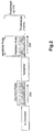
- Fig. 2 the operation of a suitable for use in the apparatus according to the invention fs laser system is shown with regenerative amplifier.
- a sequence of ultrashort (first) low power laser pulses is generated (oscillator pulses).
- the energy of these pulses is not suitable for material processing, their repetition rate is in the MHz range.
- the sequence of first laser pulses are selected and amplified in a defined manner.
- the repetition rate of the amplified (second) pulses is in the kHz range.
- the components fs-oscillator and amplifier shown in FIG. 2 correspond in FIG. 1 to the components fs-oscillator 1 and amplifier 2.
Landscapes
- Physics & Mathematics (AREA)
- Optics & Photonics (AREA)
- Engineering & Computer Science (AREA)
- Plasma & Fusion (AREA)
- Mechanical Engineering (AREA)
- Lasers (AREA)
- Laser Beam Processing (AREA)
- Electrical Discharge Machining, Electrochemical Machining, And Combined Machining (AREA)
- Glass Compositions (AREA)
Claims (9)
- Appareil pour l'usinage d'un matériau avec des impulsions de laser ultracourtes, comprenant :(a) un dispositif (1) pour la production d'un train de premières impulsions de laser dans lequel :les premières impulsions de laser ont une durée inférieure à 300 picosecondes etque la fréquence de répétition des premières impulsions est comprise entre 100 kHz et 1 GHz.(b) un dispositif de transformation (2) pour la transformation d'un premier ensemble de la suite de premières impulsions de laser en une suite de deuxièmes impulsions de laser pour l'application sur le matériau et pour l'usinage du matériau, dans lequel
les deuxièmes impulsions de laser ont chaque fois une durée inférieure à 300 picosecondes et
que la fréquence de répétition des deuxièmes impulsions de laser est comprise entre 1 Hz et 1 MHz.
caractérisé par(c) un dispositif d'analyse (3, 5, 6, 7, 15) installé de manière à appliquer sur le matériau les premières impulsions de laser, qui ne font pas partie du premier ensemble, de détecter certains résultats de cette application et de mettre ces résultats détectés à disposition en tant qu'information. - Dispositif selon la revendication 1,
caractérisé en ce que le dispositif d'analyse comprend un détecteur (6) qui met à disposition l'information en réponse au rayonnement rétrodiffusé et/ou réfléchi du matériau. - Dispositif selon l'une des revendications précédentes, comprenant en outre :(d) un dispositif de commande et/ou de réglage (9) qui coopère aussi bien avec le dispositif d'analyse (3, 5, 6, 7, 15) qu'avec le dispositif de transformation (2), dans lequel le dispositif de commande et/ou de réglage (9) reçoit des informations du dispositif d'analyse (3, 5, 6, 7, 15), le dispositif de commande et/ou de réglage (9) commandant ou règlant en fonction de ces informations la transformation des premières impulsions de laser en deuxièmes impulsions de laser et/ou l'application des deuxièmes impulsions de laser sur le matériau.
- Dispositif selon l'une des revendications précédentes,
caractérisé en ce que le dispositif de transformation comprend un amplificateur d'impulsions sélectif (2). - Dispositif selon la revendication 4,
caractérisé en ce que de l'amplificateur d'impulsions sélectif (2) sortent des premières et deuxièmes impulsions, qui sont séparées en deux rayons au moyen d'un séparateur de faisceau (3) de telle manière que l'un des rayons puisse être utilisé pour l'usinage du matériau. - Dispositif selon l'une des revendications précédentes,
caractérisé en ce que le dispositif d'analyse est installé pour réaliser des analyses interférométriques. - Dispositif selon l'une des revendications 2 à 6,
caractérisé en ce qu'un sélecteur d'impulsions (7) est prévu pour empêcher que des impulsions de laser renforcées ou leurs produits d'interférence n'atteignent le détecteur. - Dispositif pour l'usinage d'un matériau avec des impulsions de laser ultracourtes, comprenant les phases suivantes :(a) Production d'une suite de premières impulsions de laser selon laquelle- les premières impulsions de laser ont chaque fois une durée inférieure à 300 picosecondes et- la fréquence de répétition des premières impulsions de laser est comprise entre 100 kHz et 1 GHz ;(b) Transformation d'un ensemble de premières impulsions de laser en une suite de deuxièmes impulsions de laser pour l'usinage du matériau, selon laquelle- les deuxièmes impulsions de laser ont chaque fois une durée inférieure à 300 picosecondes et- la fréquence de répétition d'impulsions est comprise entre 1 Hz et 1MHz ;(c) Application d'une suite de deuxièmes impulsions de laser sélectionnés sur le matériau pour l'usinage de celui-ci,caractérisé par l'étape :(d) Application d'un deuxième ensemble de premières impulsions de laser sur le matériau pour l'analyse de celui-ci.
- Utilisation d'un dispositif selon les revendications 1 à 7 pour l'usinage du matériau.
Applications Claiming Priority (3)
| Application Number | Priority Date | Filing Date | Title |
|---|---|---|---|
| DE10020559 | 2000-04-27 | ||
| DE10020559A DE10020559A1 (de) | 2000-04-27 | 2000-04-27 | Laser-Bearbeitung von Materialien |
| PCT/EP2001/004629 WO2001083155A1 (fr) | 2000-04-27 | 2001-04-25 | Usinage au laser de materiaux |
Publications (2)
| Publication Number | Publication Date |
|---|---|
| EP1284839A1 EP1284839A1 (fr) | 2003-02-26 |
| EP1284839B1 true EP1284839B1 (fr) | 2006-01-18 |
Family
ID=7640058
Family Applications (1)
| Application Number | Title | Priority Date | Filing Date |
|---|---|---|---|
| EP01943283A Expired - Lifetime EP1284839B1 (fr) | 2000-04-27 | 2001-04-25 | Usinage au laser de materiaux |
Country Status (6)
| Country | Link |
|---|---|
| US (1) | US6787733B2 (fr) |
| EP (1) | EP1284839B1 (fr) |
| AT (1) | ATE315976T1 (fr) |
| AU (1) | AU2001265900A1 (fr) |
| DE (2) | DE10020559A1 (fr) |
| WO (1) | WO2001083155A1 (fr) |
Families Citing this family (58)
| Publication number | Priority date | Publication date | Assignee | Title |
|---|---|---|---|---|
| DE10207535B4 (de) * | 2002-02-22 | 2006-07-06 | Carl Zeiss | Vorrichtung zum Bearbeiten und Vermessen eines Objekts sowie Verfahren hierzu |
| DE10209617C1 (de) * | 2002-03-05 | 2003-08-07 | Siemens Ag | Laserbeschriftungsverfahren |
| DE10216590B4 (de) * | 2002-04-14 | 2007-06-14 | Paul Dr. Weigl | Verfahren zur maschinellen Fertigung von zahnärztlichen Restaurationen aus Keramik |
| DE10250015B3 (de) * | 2002-10-25 | 2004-09-16 | Universität Kassel | Adaptive, rückkopplungsgesteuerte Materialbearbeitung mit ultrakurzen Laserpulsen |
| DE10300091A1 (de) * | 2003-01-04 | 2004-07-29 | Lubatschowski, Holger, Dr. | Mikrotom |
| US20050064137A1 (en) * | 2003-01-29 | 2005-03-24 | Hunt Alan J. | Method for forming nanoscale features and structures produced thereby |
| US20040188872A1 (en) * | 2003-03-31 | 2004-09-30 | Jani Dharmendra M. | Method for fabricating intraocular lens with peripheral sharp edge |
| WO2004105100A2 (fr) * | 2003-05-20 | 2004-12-02 | Raydiance, Inc. | Trains d'impulsions d'ablation provenant d'amplificateurs optiques multiples |
| US7361171B2 (en) | 2003-05-20 | 2008-04-22 | Raydiance, Inc. | Man-portable optical ablation system |
| DE10333770A1 (de) | 2003-07-22 | 2005-02-17 | Carl Zeiss Meditec Ag | Verfahren zur Materialbearbeitung mit Laserimpulsen grosser spektraler Bandbreite und Vorrichtung zur Durchführung des Verfahrens |
| US8173929B1 (en) | 2003-08-11 | 2012-05-08 | Raydiance, Inc. | Methods and systems for trimming circuits |
| US8921733B2 (en) | 2003-08-11 | 2014-12-30 | Raydiance, Inc. | Methods and systems for trimming circuits |
| DE10358927B4 (de) * | 2003-12-16 | 2021-09-09 | Carl Zeiss Meditec Ag | Laservorrichtung und Verfahren zur Materialbearbeitung mittels Laserstrahlung |
| JP4348199B2 (ja) * | 2004-01-16 | 2009-10-21 | 日立ビアメカニクス株式会社 | レーザ加工方法およびレーザ加工装置 |
| US20060097430A1 (en) * | 2004-11-05 | 2006-05-11 | Li Xiaochun | UV pulsed laser machining apparatus and method |
| US8394084B2 (en) | 2005-01-10 | 2013-03-12 | Optimedica Corporation | Apparatus for patterned plasma-mediated laser trephination of the lens capsule and three dimensional phaco-segmentation |
| US8135050B1 (en) | 2005-07-19 | 2012-03-13 | Raydiance, Inc. | Automated polarization correction |
| US8221400B2 (en) | 2005-08-22 | 2012-07-17 | Sie Surgical Instruments Engineering Ag | Apparatus for and method of refractive surgery with laser pulses |
| DE102005039833A1 (de) | 2005-08-22 | 2007-03-01 | Rowiak Gmbh | Vorrichtung und Verfahren zur Materialtrennung mit Laserpulsen |
| DE102005059501A1 (de) * | 2005-12-06 | 2007-06-14 | Deutsches Zentrum für Luft- und Raumfahrt e.V. | Mehrfachpuls-Lichtemissionsvorrichtung und Verfahren zur Erzeugung einer Pulsfolge von Laserlicht-Mehrfachpulsen |
| US8189971B1 (en) | 2006-01-23 | 2012-05-29 | Raydiance, Inc. | Dispersion compensation in a chirped pulse amplification system |
| US8232687B2 (en) | 2006-04-26 | 2012-07-31 | Raydiance, Inc. | Intelligent laser interlock system |
| US9130344B2 (en) | 2006-01-23 | 2015-09-08 | Raydiance, Inc. | Automated laser tuning |
| US7444049B1 (en) | 2006-01-23 | 2008-10-28 | Raydiance, Inc. | Pulse stretcher and compressor including a multi-pass Bragg grating |
| US7822347B1 (en) | 2006-03-28 | 2010-10-26 | Raydiance, Inc. | Active tuning of temporal dispersion in an ultrashort pulse laser system |
| WO2007145702A2 (fr) * | 2006-04-10 | 2007-12-21 | Board Of Trustees Of Michigan State University | Système d'usinage par laser |
| ES2322184T3 (es) * | 2006-08-07 | 2009-06-17 | Wavelight Ag | Sistema laser para cirugia refractiva. |
| US8088124B2 (en) | 2007-01-19 | 2012-01-03 | Technolas Perfect Vision Gmbh | System and method for precise beam positioning in ocular surgery |
| EP2772234B1 (fr) | 2007-03-13 | 2021-05-26 | AMO Development, LLC | Appareil pour créer des incisions chirurgicales oculaires et de relâchement |
| DE102007028042B3 (de) * | 2007-06-14 | 2008-08-07 | Universität Zu Lübeck | Verfahren zur Laserbearbeitung transparenter Materialien |
| DE102007052969A1 (de) | 2007-11-07 | 2009-05-14 | Leibniz-Institut für Oberflächenmodifizierung e.V. | Verfahren zur elektrischen Kontaktierung von Dünnschichtleitbahnen auf organischem Träger |
| US7903326B2 (en) | 2007-11-30 | 2011-03-08 | Radiance, Inc. | Static phase mask for high-order spectral phase control in a hybrid chirped pulse amplifier system |
| DE102007058105A1 (de) * | 2007-12-03 | 2009-06-10 | Carl Zeiss Smt Ag | Vorrichtung und Verfahren zur Bearbeitung von optischen Elementen mittels Laserablation |
| WO2010007117A1 (fr) * | 2008-07-15 | 2010-01-21 | Laser Zentrum Hannover E.V. | Procédé et dispositif servant à préparer des composés organiques contenant des métaux |
| US8125704B2 (en) | 2008-08-18 | 2012-02-28 | Raydiance, Inc. | Systems and methods for controlling a pulsed laser by combining laser signals |
| US8498538B2 (en) | 2008-11-14 | 2013-07-30 | Raydiance, Inc. | Compact monolithic dispersion compensator |
| FI20096110L (fi) * | 2009-10-28 | 2011-04-29 | Lappeenrannan Teknillinen Yliopisto | Menetelmä materaalin työstämiseksi laserlaitteen avulla |
| CN102510788B (zh) * | 2010-06-14 | 2014-12-24 | 三菱电机株式会社 | 激光加工装置以及激光加工方法 |
| WO2012021748A1 (fr) | 2010-08-12 | 2012-02-16 | Raydiance, Inc. | Micro-usinage au laser de tube polymère |
| US9114482B2 (en) | 2010-09-16 | 2015-08-25 | Raydiance, Inc. | Laser based processing of layered materials |
| US10124410B2 (en) | 2010-09-25 | 2018-11-13 | Ipg Photonics Corporation | Methods and systems for coherent imaging and feedback control for modification of materials |
| US12397368B2 (en) | 2010-09-25 | 2025-08-26 | Ipg Photonics Corporation | Methods and systems for coherent imaging and feedback control for modification of materials using dynamic optical path switch in the reference arms |
| PL2619633T3 (pl) | 2010-09-25 | 2024-04-29 | Ipg Photonics (Canada) Inc. | Sposób obrazowania koherentnego i kontroli informacji zwrotnej do modyfikowania materiałów |
| DE102010063342A1 (de) | 2010-12-17 | 2012-06-21 | Laser Zentrum Hannover E.V. | Verfahren zur Herstellung von mikro-nanokombinierten Wirksystemen |
| DE102011000768B4 (de) | 2011-02-16 | 2016-08-18 | Ewag Ag | Laserbearbeitungsverfahren und Laserbearbeitungsvorrichtung mit umschaltbarer Laseranordnung |
| US10239160B2 (en) * | 2011-09-21 | 2019-03-26 | Coherent, Inc. | Systems and processes that singulate materials |
| US8807752B2 (en) | 2012-03-08 | 2014-08-19 | Technolas Perfect Vision Gmbh | System and method with refractive corrections for controlled placement of a laser beam's focal point |
| WO2014130830A1 (fr) | 2013-02-23 | 2014-08-28 | Raydiance, Inc. | Façonnage de matériaux friables à propriétés volumique et de surface régulées |
| DE102013003160A1 (de) * | 2013-02-26 | 2014-08-28 | Photon Energy Gmbh | Verfahren zur Modifizierung der Oberfläche eines Kunststoffs |
| US9398979B2 (en) | 2013-03-11 | 2016-07-26 | Technolas Perfect Vision Gmbh | Dimensional compensator for use with a patient interface |
| US9757817B2 (en) | 2013-03-13 | 2017-09-12 | Queen's University At Kingston | Methods and systems for characterizing laser machining properties by measuring keyhole dynamics using interferometry |
| ITAN20130232A1 (it) * | 2013-12-05 | 2015-06-06 | Munoz David Callejo | Metodo per ottenere una pluralita' di lamine da un lingotto di materiale con struttura monocristallina |
| CN106425111A (zh) * | 2016-11-02 | 2017-02-22 | 国神光电科技(上海)有限公司 | 一种激光划片的方法及系统以及一种激光器 |
| EP3536485B1 (fr) * | 2018-03-09 | 2024-06-12 | Concept Laser GmbH | Appareil de fabrication additive d'objets tridimensionnels |
| EP3807041B1 (fr) | 2018-07-19 | 2025-08-27 | IPG Photonics Corporation | Système et procédé de surveillance et/ou de commande de traitement à ondulation à l'aide d'une imagerie cohérente en ligne (ici) |
| CN111122568B (zh) | 2018-11-01 | 2022-04-22 | 华中科技大学苏州脑空间信息研究院 | 一种高通量光学层析成像方法及成像系统 |
| DE102019219121A1 (de) * | 2018-12-10 | 2020-06-10 | Trumpf Laser Gmbh | Verfahren zum Abtragen von Material von einer Oberfläche |
| CN113634873B (zh) * | 2021-08-31 | 2023-07-07 | 西安交通大学 | 基于干涉测量的激光加工后壁组合防护方法及系统 |
Family Cites Families (6)
| Publication number | Priority date | Publication date | Assignee | Title |
|---|---|---|---|---|
| DE69533903T2 (de) * | 1994-08-18 | 2005-12-08 | Carl Zeiss Meditec Ag | Mit optischer Kohärenz-Tomographie gesteuerter chirurgischer Apparat |
| US6150630A (en) * | 1996-01-11 | 2000-11-21 | The Regents Of The University Of California | Laser machining of explosives |
| US5720894A (en) * | 1996-01-11 | 1998-02-24 | The Regents Of The University Of California | Ultrashort pulse high repetition rate laser system for biological tissue processing |
| US6744555B2 (en) * | 1997-11-21 | 2004-06-01 | Imra America, Inc. | Ultrashort-pulse source with controllable wavelength output |
| US6053613A (en) * | 1998-05-15 | 2000-04-25 | Carl Zeiss, Inc. | Optical coherence tomography with new interferometer |
| US6559413B1 (en) * | 2001-11-28 | 2003-05-06 | The Regents Of The University Of California | Method for laser machining explosives and ordnance |
-
2000
- 2000-04-27 DE DE10020559A patent/DE10020559A1/de not_active Withdrawn
-
2001
- 2001-04-25 AU AU2001265900A patent/AU2001265900A1/en not_active Abandoned
- 2001-04-25 EP EP01943283A patent/EP1284839B1/fr not_active Expired - Lifetime
- 2001-04-25 US US10/258,786 patent/US6787733B2/en not_active Expired - Lifetime
- 2001-04-25 DE DE50108759T patent/DE50108759D1/de not_active Expired - Lifetime
- 2001-04-25 WO PCT/EP2001/004629 patent/WO2001083155A1/fr not_active Ceased
- 2001-04-25 AT AT01943283T patent/ATE315976T1/de not_active IP Right Cessation
Also Published As
| Publication number | Publication date |
|---|---|
| EP1284839A1 (fr) | 2003-02-26 |
| DE50108759D1 (de) | 2006-04-06 |
| ATE315976T1 (de) | 2006-02-15 |
| US6787733B2 (en) | 2004-09-07 |
| WO2001083155A1 (fr) | 2001-11-08 |
| US20030110862A1 (en) | 2003-06-19 |
| DE10020559A1 (de) | 2001-10-31 |
| AU2001265900A1 (en) | 2001-11-12 |
Similar Documents
| Publication | Publication Date | Title |
|---|---|---|
| EP1284839A1 (fr) | Usinage au laser de materiaux | |
| DE102007028042B3 (de) | Verfahren zur Laserbearbeitung transparenter Materialien | |
| EP1583951B1 (fr) | Microtome | |
| EP1372552B1 (fr) | Dispositif pour traitement de tissus oculaires et de diagnostic | |
| EP2521519B1 (fr) | Système laser ophtalmologique | |
| EP1537841B1 (fr) | Dispositif de traitement de l'opacité et/ou du durcissement d'un oeil fermé | |
| DE102008011811B3 (de) | Dentales Laserbearbeitungsgerät zur Bearbeitung von Zahnmaterial | |
| EP2108347B1 (fr) | Système pour la chirurgie ophtalmologique réfractive | |
| DE102012007272B4 (de) | Lasereinrichtung und Verfahren zur Konfiguration einer solchen Lasereinrichtung | |
| WO2005009666A1 (fr) | Procede de traitement de materiaux au moyen d'impulsions laser de grande largeur de bande spectrale et dispositif permettant de mettre en oeuvre ce procede | |
| EP0909553A1 (fr) | Procédé de fabrication d'implants médicaux finement structurés | |
| EP1886758B1 (fr) | Systeme laser pour chirurgie refractive | |
| EP1829510B1 (fr) | Dispositif de traitement laser d'une cornée | |
| DE102011116759A1 (de) | Ophthalmologisches Lasersystem und Verfahren zum Durchtrennen von Augengewebe | |
| EP3263077B1 (fr) | Dispositif de traitement d'un tissu | |
| DE19635998C1 (de) | Anordnung zur Laserkoagulation von unterhalb der Fundusoberfläche liegenden Retinaschichten und Verfahren zur Ermittlung von Veränderungen in tiefen Gewebeschichten der Retina | |
| DE10207535B4 (de) | Vorrichtung zum Bearbeiten und Vermessen eines Objekts sowie Verfahren hierzu | |
| DE102014117613B4 (de) | Laseranordnung und Verfahren zur Untersuchung eines Objektes | |
| DE102021109323B4 (de) | Verfahren zum Kalibrieren einer Kameraeinrichtung und einer Laserscannereinrichtung eines ophthalmologischen Lasers | |
| EP3834025A1 (fr) | Installation d'éclairage pour un microscope, microscope et procédé d'éclairage d'un volume d'échantillon dans un microscope | |
| DE10361727B3 (de) | Verfahren und Vorrichtung zur Analyse fester Materialien mit der Laser-Emissionsspektrometrie | |
| DE10148783B4 (de) | Verfahren zur nicht-invasiven optischen Bearbeitung von Geweben des Auges sowie zu dessen Diagnose und Vorrichtung zur Durchführung dieser Verfahren | |
| EP2499473A1 (fr) | Procédé et dispositif pour examiner un système à laser | |
| DE10115426A1 (de) | Vorrichtung und Verfahrens zur Laser-Ablation von organischem und anorganischem Material | |
| DE102022115566A1 (de) | Materialbearbeitungsvorrichtung und Verfahren zum Vorbereiten einer Materialbearbeitungsvorrichtung |
Legal Events
| Date | Code | Title | Description |
|---|---|---|---|
| PUAI | Public reference made under article 153(3) epc to a published international application that has entered the european phase |
Free format text: ORIGINAL CODE: 0009012 |
|
| 17P | Request for examination filed |
Effective date: 20021127 |
|
| AK | Designated contracting states |
Kind code of ref document: A1 Designated state(s): AT BE CH CY DE DK ES FI FR GB GR IE IT LI LU MC NL PT SE TR |
|
| AX | Request for extension of the european patent |
Extension state: AL LT LV MK RO SI |
|
| RIN1 | Information on inventor provided before grant (corrected) |
Inventor name: HEISTERKAMP, ALEXANDER Inventor name: MAATZ, GERO Inventor name: LUBATSCHOWSKI, HOLGER |
|
| 17Q | First examination report despatched |
Effective date: 20040914 |
|
| GRAP | Despatch of communication of intention to grant a patent |
Free format text: ORIGINAL CODE: EPIDOSNIGR1 |
|
| GRAS | Grant fee paid |
Free format text: ORIGINAL CODE: EPIDOSNIGR3 |
|
| GRAA | (expected) grant |
Free format text: ORIGINAL CODE: 0009210 |
|
| RIN1 | Information on inventor provided before grant (corrected) |
Inventor name: HEISTERKAMP, ALEXANDER Inventor name: LUBATSCHOWSKI, HOLGER Inventor name: MAATZ, GERO |
|
| AK | Designated contracting states |
Kind code of ref document: B1 Designated state(s): AT BE CH CY DE DK ES FI FR GB GR IE IT LI LU MC NL PT SE TR |
|
| PG25 | Lapsed in a contracting state [announced via postgrant information from national office to epo] |
Ref country code: IE Free format text: LAPSE BECAUSE OF FAILURE TO SUBMIT A TRANSLATION OF THE DESCRIPTION OR TO PAY THE FEE WITHIN THE PRESCRIBED TIME-LIMIT Effective date: 20060118 Ref country code: NL Free format text: LAPSE BECAUSE OF FAILURE TO SUBMIT A TRANSLATION OF THE DESCRIPTION OR TO PAY THE FEE WITHIN THE PRESCRIBED TIME-LIMIT Effective date: 20060118 Ref country code: FI Free format text: LAPSE BECAUSE OF FAILURE TO SUBMIT A TRANSLATION OF THE DESCRIPTION OR TO PAY THE FEE WITHIN THE PRESCRIBED TIME-LIMIT Effective date: 20060118 Ref country code: IT Free format text: LAPSE BECAUSE OF FAILURE TO SUBMIT A TRANSLATION OF THE DESCRIPTION OR TO PAY THE FEE WITHIN THE PRESCRIBED TIME-LIMIT;WARNING: LAPSES OF ITALIAN PATENTS WITH EFFECTIVE DATE BEFORE 2007 MAY HAVE OCCURRED AT ANY TIME BEFORE 2007. THE CORRECT EFFECTIVE DATE MAY BE DIFFERENT FROM THE ONE RECORDED. Effective date: 20060118 |
|
| REG | Reference to a national code |
Ref country code: GB Ref legal event code: FG4D Free format text: NOT ENGLISH |
|
| REG | Reference to a national code |
Ref country code: CH Ref legal event code: EP |
|
| REG | Reference to a national code |
Ref country code: CH Ref legal event code: NV Representative=s name: ZIMMERLI, WAGNER & PARTNER AG |
|
| REG | Reference to a national code |
Ref country code: IE Ref legal event code: FG4D Free format text: LANGUAGE OF EP DOCUMENT: GERMAN |
|
| GBT | Gb: translation of ep patent filed (gb section 77(6)(a)/1977) |
Effective date: 20060309 |
|
| REF | Corresponds to: |
Ref document number: 50108759 Country of ref document: DE Date of ref document: 20060406 Kind code of ref document: P |
|
| PG25 | Lapsed in a contracting state [announced via postgrant information from national office to epo] |
Ref country code: SE Free format text: LAPSE BECAUSE OF FAILURE TO SUBMIT A TRANSLATION OF THE DESCRIPTION OR TO PAY THE FEE WITHIN THE PRESCRIBED TIME-LIMIT Effective date: 20060418 Ref country code: DK Free format text: LAPSE BECAUSE OF FAILURE TO SUBMIT A TRANSLATION OF THE DESCRIPTION OR TO PAY THE FEE WITHIN THE PRESCRIBED TIME-LIMIT Effective date: 20060418 |
|
| PG25 | Lapsed in a contracting state [announced via postgrant information from national office to epo] |
Ref country code: ES Free format text: LAPSE BECAUSE OF FAILURE TO SUBMIT A TRANSLATION OF THE DESCRIPTION OR TO PAY THE FEE WITHIN THE PRESCRIBED TIME-LIMIT Effective date: 20060429 |
|
| PG25 | Lapsed in a contracting state [announced via postgrant information from national office to epo] |
Ref country code: BE Free format text: LAPSE BECAUSE OF NON-PAYMENT OF DUE FEES Effective date: 20060430 Ref country code: MC Free format text: LAPSE BECAUSE OF NON-PAYMENT OF DUE FEES Effective date: 20060430 |
|
| PG25 | Lapsed in a contracting state [announced via postgrant information from national office to epo] |
Ref country code: PT Free format text: LAPSE BECAUSE OF FAILURE TO SUBMIT A TRANSLATION OF THE DESCRIPTION OR TO PAY THE FEE WITHIN THE PRESCRIBED TIME-LIMIT Effective date: 20060619 |
|
| NLV1 | Nl: lapsed or annulled due to failure to fulfill the requirements of art. 29p and 29m of the patents act | ||
| REG | Reference to a national code |
Ref country code: IE Ref legal event code: FD4D |
|
| ET | Fr: translation filed | ||
| PLBE | No opposition filed within time limit |
Free format text: ORIGINAL CODE: 0009261 |
|
| STAA | Information on the status of an ep patent application or granted ep patent |
Free format text: STATUS: NO OPPOSITION FILED WITHIN TIME LIMIT |
|
| 26N | No opposition filed |
Effective date: 20061019 |
|
| BERE | Be: lapsed |
Owner name: LASER ZENTRUM HANNOVER E.V. Effective date: 20060430 |
|
| PG25 | Lapsed in a contracting state [announced via postgrant information from national office to epo] |
Ref country code: GR Free format text: LAPSE BECAUSE OF FAILURE TO SUBMIT A TRANSLATION OF THE DESCRIPTION OR TO PAY THE FEE WITHIN THE PRESCRIBED TIME-LIMIT Effective date: 20060419 |
|
| PG25 | Lapsed in a contracting state [announced via postgrant information from national office to epo] |
Ref country code: TR Free format text: LAPSE BECAUSE OF FAILURE TO SUBMIT A TRANSLATION OF THE DESCRIPTION OR TO PAY THE FEE WITHIN THE PRESCRIBED TIME-LIMIT Effective date: 20060118 Ref country code: LU Free format text: LAPSE BECAUSE OF NON-PAYMENT OF DUE FEES Effective date: 20060425 |
|
| PGFP | Annual fee paid to national office [announced via postgrant information from national office to epo] |
Ref country code: CH Payment date: 20080428 Year of fee payment: 8 |
|
| PGFP | Annual fee paid to national office [announced via postgrant information from national office to epo] |
Ref country code: AT Payment date: 20080425 Year of fee payment: 8 |
|
| PG25 | Lapsed in a contracting state [announced via postgrant information from national office to epo] |
Ref country code: CY Free format text: LAPSE BECAUSE OF FAILURE TO SUBMIT A TRANSLATION OF THE DESCRIPTION OR TO PAY THE FEE WITHIN THE PRESCRIBED TIME-LIMIT Effective date: 20060118 |
|
| REG | Reference to a national code |
Ref country code: CH Ref legal event code: PFA Owner name: LASER ZENTRUM HANNOVER E.V. Free format text: LASER ZENTRUM HANNOVER E.V.#HOLLERITHALLEE 8#D-30419 HANNOVER (DE) -TRANSFER TO- LASER ZENTRUM HANNOVER E.V.#HOLLERITHALLEE 8#D-30419 HANNOVER (DE) |
|
| REG | Reference to a national code |
Ref country code: CH Ref legal event code: PL |
|
| PG25 | Lapsed in a contracting state [announced via postgrant information from national office to epo] |
Ref country code: LI Free format text: LAPSE BECAUSE OF NON-PAYMENT OF DUE FEES Effective date: 20090430 Ref country code: CH Free format text: LAPSE BECAUSE OF NON-PAYMENT OF DUE FEES Effective date: 20090430 Ref country code: AT Free format text: LAPSE BECAUSE OF NON-PAYMENT OF DUE FEES Effective date: 20090425 |
|
| REG | Reference to a national code |
Ref country code: FR Ref legal event code: PLFP Year of fee payment: 16 |
|
| REG | Reference to a national code |
Ref country code: FR Ref legal event code: PLFP Year of fee payment: 17 |
|
| PGFP | Annual fee paid to national office [announced via postgrant information from national office to epo] |
Ref country code: FR Payment date: 20170424 Year of fee payment: 17 Ref country code: GB Payment date: 20170425 Year of fee payment: 17 |
|
| PGFP | Annual fee paid to national office [announced via postgrant information from national office to epo] |
Ref country code: DE Payment date: 20180503 Year of fee payment: 18 |
|
| GBPC | Gb: european patent ceased through non-payment of renewal fee |
Effective date: 20180425 |
|
| PG25 | Lapsed in a contracting state [announced via postgrant information from national office to epo] |
Ref country code: GB Free format text: LAPSE BECAUSE OF NON-PAYMENT OF DUE FEES Effective date: 20180425 |
|
| PG25 | Lapsed in a contracting state [announced via postgrant information from national office to epo] |
Ref country code: FR Free format text: LAPSE BECAUSE OF NON-PAYMENT OF DUE FEES Effective date: 20180430 |
|
| REG | Reference to a national code |
Ref country code: DE Ref legal event code: R119 Ref document number: 50108759 Country of ref document: DE |
|
| PG25 | Lapsed in a contracting state [announced via postgrant information from national office to epo] |
Ref country code: DE Free format text: LAPSE BECAUSE OF NON-PAYMENT OF DUE FEES Effective date: 20191101 |