EP1284866B1 - Element donneur comportant une dispersion aqueuse - Google Patents
Element donneur comportant une dispersion aqueuse Download PDFInfo
- Publication number
- EP1284866B1 EP1284866B1 EP01935371A EP01935371A EP1284866B1 EP 1284866 B1 EP1284866 B1 EP 1284866B1 EP 01935371 A EP01935371 A EP 01935371A EP 01935371 A EP01935371 A EP 01935371A EP 1284866 B1 EP1284866 B1 EP 1284866B1
- Authority
- EP
- European Patent Office
- Prior art keywords
- layer
- image
- thermally imageable
- donor element
- receiver
- Prior art date
- Legal status (The legal status is an assumption and is not a legal conclusion. Google has not performed a legal analysis and makes no representation as to the accuracy of the status listed.)
- Expired - Lifetime
Links
- 239000006185 dispersion Substances 0.000 title claims description 43
- 150000001875 compounds Chemical class 0.000 claims description 58
- 239000000758 substrate Substances 0.000 claims description 55
- 239000002270 dispersing agent Substances 0.000 claims description 54
- -1 alkyl methacrylate Chemical compound 0.000 claims description 49
- PPBRXRYQALVLMV-UHFFFAOYSA-N Styrene Chemical compound C=CC1=CC=CC=C1 PPBRXRYQALVLMV-UHFFFAOYSA-N 0.000 claims description 47
- 239000000049 pigment Substances 0.000 claims description 44
- 229920000642 polymer Polymers 0.000 claims description 42
- 229920001577 copolymer Polymers 0.000 claims description 37
- 239000000654 additive Substances 0.000 claims description 36
- 239000003086 colorant Substances 0.000 claims description 34
- 238000000034 method Methods 0.000 claims description 32
- 230000005855 radiation Effects 0.000 claims description 20
- 230000000996 additive effect Effects 0.000 claims description 17
- 239000004973 liquid crystal related substance Substances 0.000 claims description 16
- 150000003839 salts Chemical class 0.000 claims description 16
- 230000003321 amplification Effects 0.000 claims description 15
- 238000003199 nucleic acid amplification method Methods 0.000 claims description 15
- CERQOIWHTDAKMF-UHFFFAOYSA-N Methacrylic acid Chemical compound CC(=C)C(O)=O CERQOIWHTDAKMF-UHFFFAOYSA-N 0.000 claims description 14
- NIXOWILDQLNWCW-UHFFFAOYSA-N 2-Propenoic acid Natural products OC(=O)C=C NIXOWILDQLNWCW-UHFFFAOYSA-N 0.000 claims description 13
- VVQNEPGJFQJSBK-UHFFFAOYSA-N Methyl methacrylate Chemical compound COC(=O)C(C)=C VVQNEPGJFQJSBK-UHFFFAOYSA-N 0.000 claims description 12
- 125000000217 alkyl group Chemical group 0.000 claims description 12
- SMZOUWXMTYCWNB-UHFFFAOYSA-N 2-(2-methoxy-5-methylphenyl)ethanamine Chemical compound COC1=CC=C(C)C=C1CCN SMZOUWXMTYCWNB-UHFFFAOYSA-N 0.000 claims description 11
- SOGAXMICEFXMKE-UHFFFAOYSA-N Butylmethacrylate Chemical compound CCCCOC(=O)C(C)=C SOGAXMICEFXMKE-UHFFFAOYSA-N 0.000 claims description 10
- NIXOWILDQLNWCW-UHFFFAOYSA-M Acrylate Chemical compound [O-]C(=O)C=C NIXOWILDQLNWCW-UHFFFAOYSA-M 0.000 claims description 8
- 125000000219 ethylidene group Chemical group [H]C(=[*])C([H])([H])[H] 0.000 claims description 8
- 239000000178 monomer Substances 0.000 claims description 8
- ITMCEJHCFYSIIV-UHFFFAOYSA-N triflic acid Chemical compound OS(=O)(=O)C(F)(F)F ITMCEJHCFYSIIV-UHFFFAOYSA-N 0.000 claims description 8
- CERQOIWHTDAKMF-UHFFFAOYSA-M Methacrylate Chemical compound CC(=C)C([O-])=O CERQOIWHTDAKMF-UHFFFAOYSA-M 0.000 claims description 7
- RKJUIXBNRJVNHR-UHFFFAOYSA-N 3H-indole Chemical compound C1=CC=C2CC=NC2=C1 RKJUIXBNRJVNHR-UHFFFAOYSA-N 0.000 claims description 6
- 125000005250 alkyl acrylate group Chemical group 0.000 claims description 6
- 125000004432 carbon atom Chemical group C* 0.000 claims description 6
- 229920000058 polyacrylate Polymers 0.000 claims description 6
- 125000000391 vinyl group Chemical group [H]C([*])=C([H])[H] 0.000 claims description 5
- 239000002253 acid Substances 0.000 claims description 4
- 150000001252 acrylic acid derivatives Chemical class 0.000 claims description 4
- 229920000578 graft copolymer Polymers 0.000 claims description 4
- OKYDCMQQLGECPI-UHFFFAOYSA-N thiopyrylium Chemical compound C1=CC=[S+]C=C1 OKYDCMQQLGECPI-UHFFFAOYSA-N 0.000 claims description 4
- AWZSJBDJHOOBGX-UHFFFAOYSA-N 4-[2-[2-[2-chloro-3-[2-[1,1-dimethyl-3-(4-sulfonatobutyl)benzo[e]indol-3-ium-2-yl]ethenyl]cyclohex-2-en-1-ylidene]ethylidene]-1,1-dimethyl-3h-benzo[e]indol-3-ium-3-yl]butane-1-sulfonate Chemical compound OS(=O)(=O)CCCCN1C2=CC=C3C=CC=CC3=C2C(C)(C)\C1=C/C=C\1C(Cl)=C(\C=C\C=2C(C3=C4C=CC=CC4=CC=C3[N+]=2CCCCS([O-])(=O)=O)(C)C)CCC/1 AWZSJBDJHOOBGX-UHFFFAOYSA-N 0.000 claims description 3
- 239000004594 Masterbatch (MB) Substances 0.000 claims description 3
- SIKJAQJRHWYJAI-UHFFFAOYSA-O 1H-indol-1-ium Chemical compound C1=CC=C2[NH2+]C=CC2=C1 SIKJAQJRHWYJAI-UHFFFAOYSA-O 0.000 claims description 2
- 238000010923 batch production Methods 0.000 claims 2
- 239000010410 layer Substances 0.000 description 280
- 239000000386 donor Substances 0.000 description 81
- 239000000975 dye Substances 0.000 description 43
- 239000000203 mixture Substances 0.000 description 35
- 239000000463 material Substances 0.000 description 31
- 239000011230 binding agent Substances 0.000 description 27
- 238000000576 coating method Methods 0.000 description 27
- 239000007787 solid Substances 0.000 description 27
- 239000002245 particle Substances 0.000 description 24
- XLYOFNOQVPJJNP-UHFFFAOYSA-N water Substances O XLYOFNOQVPJJNP-UHFFFAOYSA-N 0.000 description 22
- 239000011248 coating agent Substances 0.000 description 21
- 238000010438 heat treatment Methods 0.000 description 20
- 230000008569 process Effects 0.000 description 20
- 230000003287 optical effect Effects 0.000 description 19
- 229920000728 polyester Polymers 0.000 description 18
- 239000010408 film Substances 0.000 description 17
- 239000002904 solvent Substances 0.000 description 15
- 238000003384 imaging method Methods 0.000 description 13
- 238000003475 lamination Methods 0.000 description 12
- 239000004094 surface-active agent Substances 0.000 description 12
- 238000000354 decomposition reaction Methods 0.000 description 11
- 229940102838 methylmethacrylate Drugs 0.000 description 11
- 239000000243 solution Substances 0.000 description 11
- BAPJBEWLBFYGME-UHFFFAOYSA-N Methyl acrylate Chemical compound COC(=O)C=C BAPJBEWLBFYGME-UHFFFAOYSA-N 0.000 description 10
- 238000010586 diagram Methods 0.000 description 10
- 239000011521 glass Substances 0.000 description 10
- 229920001223 polyethylene glycol Polymers 0.000 description 10
- 230000035945 sensitivity Effects 0.000 description 10
- 239000006096 absorbing agent Substances 0.000 description 9
- 239000004615 ingredient Substances 0.000 description 9
- 229910052751 metal Inorganic materials 0.000 description 9
- 239000004014 plasticizer Substances 0.000 description 9
- CQEYYJKEWSMYFG-UHFFFAOYSA-N butyl acrylate Chemical compound CCCCOC(=O)C=C CQEYYJKEWSMYFG-UHFFFAOYSA-N 0.000 description 8
- 239000002184 metal Substances 0.000 description 8
- 229920001610 polycaprolactone Polymers 0.000 description 8
- 239000004800 polyvinyl chloride Substances 0.000 description 8
- 229920000915 polyvinyl chloride Polymers 0.000 description 8
- 238000000926 separation method Methods 0.000 description 8
- VGGSQFUCUMXWEO-UHFFFAOYSA-N Ethene Chemical compound C=C VGGSQFUCUMXWEO-UHFFFAOYSA-N 0.000 description 7
- 239000005977 Ethylene Substances 0.000 description 7
- GWEVSGVZZGPLCZ-UHFFFAOYSA-N Titan oxide Chemical compound O=[Ti]=O GWEVSGVZZGPLCZ-UHFFFAOYSA-N 0.000 description 7
- 229910052804 chromium Inorganic materials 0.000 description 7
- 239000011651 chromium Substances 0.000 description 7
- 238000002156 mixing Methods 0.000 description 7
- 229920000139 polyethylene terephthalate Polymers 0.000 description 7
- 239000005020 polyethylene terephthalate Substances 0.000 description 7
- 238000010521 absorption reaction Methods 0.000 description 6
- 230000015572 biosynthetic process Effects 0.000 description 6
- 239000004632 polycaprolactone Substances 0.000 description 6
- 229940117958 vinyl acetate Drugs 0.000 description 6
- 229940058020 2-amino-2-methyl-1-propanol Drugs 0.000 description 5
- VYPSYNLAJGMNEJ-UHFFFAOYSA-N Silicium dioxide Chemical compound O=[Si]=O VYPSYNLAJGMNEJ-UHFFFAOYSA-N 0.000 description 5
- CBTVGIZVANVGBH-UHFFFAOYSA-N aminomethyl propanol Chemical compound CC(C)(N)CO CBTVGIZVANVGBH-UHFFFAOYSA-N 0.000 description 5
- 239000007844 bleaching agent Substances 0.000 description 5
- 229920001400 block copolymer Polymers 0.000 description 5
- 239000003795 chemical substances by application Substances 0.000 description 5
- 238000004132 cross linking Methods 0.000 description 5
- 229920001519 homopolymer Polymers 0.000 description 5
- 239000004417 polycarbonate Substances 0.000 description 5
- 229920000515 polycarbonate Polymers 0.000 description 5
- 229920000573 polyethylene Polymers 0.000 description 5
- 229920001169 thermoplastic Polymers 0.000 description 5
- VYZAMTAEIAYCRO-UHFFFAOYSA-N Chromium Chemical compound [Cr] VYZAMTAEIAYCRO-UHFFFAOYSA-N 0.000 description 4
- KFZMGEQAYNKOFK-UHFFFAOYSA-N Isopropanol Chemical compound CC(C)O KFZMGEQAYNKOFK-UHFFFAOYSA-N 0.000 description 4
- 239000004698 Polyethylene Substances 0.000 description 4
- 238000002835 absorbance Methods 0.000 description 4
- 230000008901 benefit Effects 0.000 description 4
- 125000002091 cationic group Chemical group 0.000 description 4
- 239000000945 filler Substances 0.000 description 4
- 238000009472 formulation Methods 0.000 description 4
- 230000009477 glass transition Effects 0.000 description 4
- 238000010030 laminating Methods 0.000 description 4
- 238000004519 manufacturing process Methods 0.000 description 4
- 125000002496 methyl group Chemical group [H]C([H])([H])* 0.000 description 4
- 230000003472 neutralizing effect Effects 0.000 description 4
- 229920001296 polysiloxane Polymers 0.000 description 4
- 239000004814 polyurethane Substances 0.000 description 4
- 229920002635 polyurethane Polymers 0.000 description 4
- JOXIMZWYDAKGHI-UHFFFAOYSA-N toluene-4-sulfonic acid Chemical compound CC1=CC=C(S(O)(=O)=O)C=C1 JOXIMZWYDAKGHI-UHFFFAOYSA-N 0.000 description 4
- QTBSBXVTEAMEQO-UHFFFAOYSA-N Acetic acid Chemical compound CC(O)=O QTBSBXVTEAMEQO-UHFFFAOYSA-N 0.000 description 3
- NLHHRLWOUZZQLW-UHFFFAOYSA-N Acrylonitrile Chemical compound C=CC#N NLHHRLWOUZZQLW-UHFFFAOYSA-N 0.000 description 3
- 229920002799 BoPET Polymers 0.000 description 3
- OKTJSMMVPCPJKN-UHFFFAOYSA-N Carbon Chemical compound [C] OKTJSMMVPCPJKN-UHFFFAOYSA-N 0.000 description 3
- 239000004952 Polyamide Substances 0.000 description 3
- KWYUFKZDYYNOTN-UHFFFAOYSA-M Potassium hydroxide Chemical compound [OH-].[K+] KWYUFKZDYYNOTN-UHFFFAOYSA-M 0.000 description 3
- HEMHJVSKTPXQMS-UHFFFAOYSA-M Sodium hydroxide Chemical compound [OH-].[Na+] HEMHJVSKTPXQMS-UHFFFAOYSA-M 0.000 description 3
- QAOWNCQODCNURD-UHFFFAOYSA-L Sulfate Chemical compound [O-]S([O-])(=O)=O QAOWNCQODCNURD-UHFFFAOYSA-L 0.000 description 3
- XTXRWKRVRITETP-UHFFFAOYSA-N Vinyl acetate Chemical compound CC(=O)OC=C XTXRWKRVRITETP-UHFFFAOYSA-N 0.000 description 3
- BZHJMEDXRYGGRV-UHFFFAOYSA-N Vinyl chloride Chemical compound ClC=C BZHJMEDXRYGGRV-UHFFFAOYSA-N 0.000 description 3
- 239000000956 alloy Substances 0.000 description 3
- 229910045601 alloy Inorganic materials 0.000 description 3
- 229910052782 aluminium Inorganic materials 0.000 description 3
- 150000001450 anions Chemical class 0.000 description 3
- 239000002216 antistatic agent Substances 0.000 description 3
- 230000004888 barrier function Effects 0.000 description 3
- 229910052799 carbon Inorganic materials 0.000 description 3
- 239000006229 carbon black Substances 0.000 description 3
- 238000006243 chemical reaction Methods 0.000 description 3
- XCJYREBRNVKWGJ-UHFFFAOYSA-N copper(II) phthalocyanine Chemical compound [Cu+2].C12=CC=CC=C2C(N=C2[N-]C(C3=CC=CC=C32)=N2)=NC1=NC([C]1C=CC=CC1=1)=NC=1N=C1[C]3C=CC=CC3=C2[N-]1 XCJYREBRNVKWGJ-UHFFFAOYSA-N 0.000 description 3
- 239000006184 cosolvent Substances 0.000 description 3
- 150000002148 esters Chemical class 0.000 description 3
- 125000001495 ethyl group Chemical group [H]C([H])([H])C([H])([H])* 0.000 description 3
- 229920002313 fluoropolymer Polymers 0.000 description 3
- 239000004811 fluoropolymer Substances 0.000 description 3
- 239000004816 latex Substances 0.000 description 3
- 229920000126 latex Polymers 0.000 description 3
- 230000000670 limiting effect Effects 0.000 description 3
- 230000033001 locomotion Effects 0.000 description 3
- 150000002739 metals Chemical class 0.000 description 3
- 229910052759 nickel Inorganic materials 0.000 description 3
- 229920002647 polyamide Polymers 0.000 description 3
- 238000002360 preparation method Methods 0.000 description 3
- 239000000047 product Substances 0.000 description 3
- 238000001228 spectrum Methods 0.000 description 3
- 229920001897 terpolymer Polymers 0.000 description 3
- 125000000383 tetramethylene group Chemical group [H]C([H])([*:1])C([H])([H])C([H])([H])C([H])([H])[*:2] 0.000 description 3
- 238000001931 thermography Methods 0.000 description 3
- 229910052726 zirconium Inorganic materials 0.000 description 3
- BHDWMMMNNQFZQJ-UHFFFAOYSA-M (2z)-2-[(2z)-2-[2-chloro-3-[(e)-2-(1,3,3-trimethylindol-1-ium-2-yl)ethenyl]cyclopent-2-en-1-ylidene]ethylidene]-1,3,3-trimethylindole;trifluoromethanesulfonate Chemical compound [O-]S(=O)(=O)C(F)(F)F.CC1(C)C2=CC=CC=C2N(C)\C1=C\C=C/1C(Cl)=C(\C=C\C=2C(C3=CC=CC=C3[N+]=2C)(C)C)CC\1 BHDWMMMNNQFZQJ-UHFFFAOYSA-M 0.000 description 2
- QGZKDVFQNNGYKY-UHFFFAOYSA-O Ammonium Chemical compound [NH4+] QGZKDVFQNNGYKY-UHFFFAOYSA-O 0.000 description 2
- 101100456957 Arabidopsis thaliana MEX1 gene Proteins 0.000 description 2
- IJGRMHOSHXDMSA-UHFFFAOYSA-N Atomic nitrogen Chemical compound N#N IJGRMHOSHXDMSA-UHFFFAOYSA-N 0.000 description 2
- CPELXLSAUQHCOX-UHFFFAOYSA-M Bromide Chemical compound [Br-] CPELXLSAUQHCOX-UHFFFAOYSA-M 0.000 description 2
- VEXZGXHMUGYJMC-UHFFFAOYSA-M Chloride anion Chemical compound [Cl-] VEXZGXHMUGYJMC-UHFFFAOYSA-M 0.000 description 2
- VEXZGXHMUGYJMC-UHFFFAOYSA-N Hydrochloric acid Chemical compound Cl VEXZGXHMUGYJMC-UHFFFAOYSA-N 0.000 description 2
- MHAJPDPJQMAIIY-UHFFFAOYSA-N Hydrogen peroxide Chemical compound OO MHAJPDPJQMAIIY-UHFFFAOYSA-N 0.000 description 2
- UQSXHKLRYXJYBZ-UHFFFAOYSA-N Iron oxide Chemical compound [Fe]=O UQSXHKLRYXJYBZ-UHFFFAOYSA-N 0.000 description 2
- 239000005041 Mylar™ Substances 0.000 description 2
- 239000000020 Nitrocellulose Substances 0.000 description 2
- NBIIXXVUZAFLBC-UHFFFAOYSA-N Phosphoric acid Chemical compound OP(O)(O)=O NBIIXXVUZAFLBC-UHFFFAOYSA-N 0.000 description 2
- 239000002202 Polyethylene glycol Substances 0.000 description 2
- 101100355951 Synechocystis sp. (strain PCC 6803 / Kazusa) rcp1 gene Proteins 0.000 description 2
- 238000000862 absorption spectrum Methods 0.000 description 2
- 230000002411 adverse Effects 0.000 description 2
- 238000005054 agglomeration Methods 0.000 description 2
- 230000002776 aggregation Effects 0.000 description 2
- 150000001336 alkenes Chemical class 0.000 description 2
- 150000001412 amines Chemical class 0.000 description 2
- ROOXNKNUYICQNP-UHFFFAOYSA-N ammonium persulfate Chemical compound [NH4+].[NH4+].[O-]S(=O)(=O)OOS([O-])(=O)=O ROOXNKNUYICQNP-UHFFFAOYSA-N 0.000 description 2
- 125000000129 anionic group Chemical group 0.000 description 2
- 239000013011 aqueous formulation Substances 0.000 description 2
- QVGXLLKOCUKJST-UHFFFAOYSA-N atomic oxygen Chemical compound [O] QVGXLLKOCUKJST-UHFFFAOYSA-N 0.000 description 2
- 238000004061 bleaching Methods 0.000 description 2
- 239000008199 coating composition Substances 0.000 description 2
- 238000005336 cracking Methods 0.000 description 2
- 230000007547 defect Effects 0.000 description 2
- 150000008049 diazo compounds Chemical class 0.000 description 2
- DOIRQSBPFJWKBE-UHFFFAOYSA-N dibutyl phthalate Chemical compound CCCCOC(=O)C1=CC=CC=C1C(=O)OCCCC DOIRQSBPFJWKBE-UHFFFAOYSA-N 0.000 description 2
- 150000001990 dicarboxylic acid derivatives Chemical class 0.000 description 2
- 230000000694 effects Effects 0.000 description 2
- 125000001153 fluoro group Chemical group F* 0.000 description 2
- 125000005842 heteroatom Chemical group 0.000 description 2
- 150000001469 hydantoins Chemical class 0.000 description 2
- FPYJFEHAWHCUMM-UHFFFAOYSA-N maleic anhydride Chemical compound O=C1OC(=O)C=C1 FPYJFEHAWHCUMM-UHFFFAOYSA-N 0.000 description 2
- 238000002844 melting Methods 0.000 description 2
- 230000008018 melting Effects 0.000 description 2
- 238000013508 migration Methods 0.000 description 2
- 125000004108 n-butyl group Chemical group [H]C([H])([H])C([H])([H])C([H])([H])C([H])([H])* 0.000 description 2
- 229920001220 nitrocellulos Polymers 0.000 description 2
- 229910052755 nonmetal Inorganic materials 0.000 description 2
- 229920000847 nonoxynol Polymers 0.000 description 2
- JRZJOMJEPLMPRA-UHFFFAOYSA-N olefin Natural products CCCCCCCC=C JRZJOMJEPLMPRA-UHFFFAOYSA-N 0.000 description 2
- 229910052760 oxygen Inorganic materials 0.000 description 2
- 239000001301 oxygen Substances 0.000 description 2
- 150000002978 peroxides Chemical class 0.000 description 2
- JRKICGRDRMAZLK-UHFFFAOYSA-L persulfate group Chemical group S(=O)(=O)([O-])OOS(=O)(=O)[O-] JRKICGRDRMAZLK-UHFFFAOYSA-L 0.000 description 2
- 229920000193 polymethacrylate Polymers 0.000 description 2
- 229920000098 polyolefin Polymers 0.000 description 2
- 229920006324 polyoxymethylene Polymers 0.000 description 2
- 239000011118 polyvinyl acetate Substances 0.000 description 2
- 229920002689 polyvinyl acetate Polymers 0.000 description 2
- 229920002451 polyvinyl alcohol Polymers 0.000 description 2
- 235000019422 polyvinyl alcohol Nutrition 0.000 description 2
- 239000010453 quartz Substances 0.000 description 2
- 239000012748 slip agent Substances 0.000 description 2
- 125000006850 spacer group Chemical group 0.000 description 2
- 150000003467 sulfuric acid derivatives Chemical class 0.000 description 2
- 239000002344 surface layer Substances 0.000 description 2
- 238000003786 synthesis reaction Methods 0.000 description 2
- 239000012780 transparent material Substances 0.000 description 2
- URAYPUMNDPQOKB-UHFFFAOYSA-N triacetin Chemical compound CC(=O)OCC(OC(C)=O)COC(C)=O URAYPUMNDPQOKB-UHFFFAOYSA-N 0.000 description 2
- 229920002818 (Hydroxyethyl)methacrylate Polymers 0.000 description 1
- KEQGZUUPPQEDPF-UHFFFAOYSA-N 1,3-dichloro-5,5-dimethylimidazolidine-2,4-dione Chemical compound CC1(C)N(Cl)C(=O)N(Cl)C1=O KEQGZUUPPQEDPF-UHFFFAOYSA-N 0.000 description 1
- YVXDRFYHWWPSOA-BQYQJAHWSA-N 1-methyl-4-[(e)-2-phenylethenyl]pyridin-1-ium Chemical group C1=C[N+](C)=CC=C1\C=C\C1=CC=CC=C1 YVXDRFYHWWPSOA-BQYQJAHWSA-N 0.000 description 1
- WOHLSTOWRAOMSG-UHFFFAOYSA-N 2,3-dihydro-1,3-benzothiazole Chemical compound C1=CC=C2SCNC2=C1 WOHLSTOWRAOMSG-UHFFFAOYSA-N 0.000 description 1
- HRCMXYXVAWHBTH-UHFFFAOYSA-N 2,3-dihydro-1,3-benzoxazole Chemical compound C1=CC=C2OCNC2=C1 HRCMXYXVAWHBTH-UHFFFAOYSA-N 0.000 description 1
- TXWSZJSDZKWQAU-UHFFFAOYSA-N 2,9-dimethyl-5,12-dihydroquinolino[2,3-b]acridine-7,14-dione Chemical compound N1C2=CC=C(C)C=C2C(=O)C2=C1C=C(C(=O)C=1C(=CC=C(C=1)C)N1)C1=C2 TXWSZJSDZKWQAU-UHFFFAOYSA-N 0.000 description 1
- OAYXUHPQHDHDDZ-UHFFFAOYSA-N 2-(2-butoxyethoxy)ethanol Chemical compound CCCCOCCOCCO OAYXUHPQHDHDDZ-UHFFFAOYSA-N 0.000 description 1
- CUDYYMUUJHLCGZ-UHFFFAOYSA-N 2-(2-methoxypropoxy)propan-1-ol Chemical compound COC(C)COC(C)CO CUDYYMUUJHLCGZ-UHFFFAOYSA-N 0.000 description 1
- IEORSVTYLWZQJQ-UHFFFAOYSA-N 2-(2-nonylphenoxy)ethanol Chemical compound CCCCCCCCCC1=CC=CC=C1OCCO IEORSVTYLWZQJQ-UHFFFAOYSA-N 0.000 description 1
- LBLYYCQCTBFVLH-UHFFFAOYSA-N 2-Methylbenzenesulfonic acid Chemical compound CC1=CC=CC=C1S(O)(=O)=O LBLYYCQCTBFVLH-UHFFFAOYSA-N 0.000 description 1
- AYKYXWQEBUNJCN-UHFFFAOYSA-N 3-methylfuran-2,5-dione Chemical compound CC1=CC(=O)OC1=O AYKYXWQEBUNJCN-UHFFFAOYSA-N 0.000 description 1
- OFNISBHGPNMTMS-UHFFFAOYSA-N 3-methylideneoxolane-2,5-dione Chemical compound C=C1CC(=O)OC1=O OFNISBHGPNMTMS-UHFFFAOYSA-N 0.000 description 1
- MOWKTPHUWHQZSC-UHFFFAOYSA-N 3h-naphtho[1,2-g]indole Chemical compound C1=CC=C2C3=CC=C4C=CNC4=C3C=CC2=C1 MOWKTPHUWHQZSC-UHFFFAOYSA-N 0.000 description 1
- 229920002126 Acrylic acid copolymer Polymers 0.000 description 1
- 229920000178 Acrylic resin Polymers 0.000 description 1
- 239000004925 Acrylic resin Substances 0.000 description 1
- UGFAIRIUMAVXCW-UHFFFAOYSA-N Carbon monoxide Chemical compound [O+]#[C-] UGFAIRIUMAVXCW-UHFFFAOYSA-N 0.000 description 1
- 239000004593 Epoxy Chemical group 0.000 description 1
- PEDCQBHIVMGVHV-UHFFFAOYSA-N Glycerine Chemical class OCC(O)CO PEDCQBHIVMGVHV-UHFFFAOYSA-N 0.000 description 1
- WOBHKFSMXKNTIM-UHFFFAOYSA-N Hydroxyethyl methacrylate Chemical compound CC(=C)C(=O)OCCO WOBHKFSMXKNTIM-UHFFFAOYSA-N 0.000 description 1
- 235000017858 Laurus nobilis Nutrition 0.000 description 1
- 229920000877 Melamine resin Polymers 0.000 description 1
- 101000644539 Panax ginseng Squalene synthase 3 Proteins 0.000 description 1
- 239000004695 Polyether sulfone Substances 0.000 description 1
- 239000004642 Polyimide Substances 0.000 description 1
- 229920001710 Polyorthoester Polymers 0.000 description 1
- 229920001328 Polyvinylidene chloride Polymers 0.000 description 1
- OFOBLEOULBTSOW-UHFFFAOYSA-N Propanedioic acid Natural products OC(=O)CC(O)=O OFOBLEOULBTSOW-UHFFFAOYSA-N 0.000 description 1
- 235000005212 Terminalia tomentosa Nutrition 0.000 description 1
- 244000125380 Terminalia tomentosa Species 0.000 description 1
- 229920000690 Tyvek Polymers 0.000 description 1
- 239000004775 Tyvek Substances 0.000 description 1
- 150000008065 acid anhydrides Chemical group 0.000 description 1
- 239000000159 acid neutralizing agent Substances 0.000 description 1
- 229920000800 acrylic rubber Polymers 0.000 description 1
- 239000000853 adhesive Substances 0.000 description 1
- 230000001070 adhesive effect Effects 0.000 description 1
- 229910000147 aluminium phosphate Inorganic materials 0.000 description 1
- 229910001870 ammonium persulfate Inorganic materials 0.000 description 1
- 150000003863 ammonium salts Chemical class 0.000 description 1
- 238000004873 anchoring Methods 0.000 description 1
- 229910052787 antimony Inorganic materials 0.000 description 1
- 239000000010 aprotic solvent Substances 0.000 description 1
- 239000007864 aqueous solution Substances 0.000 description 1
- 150000004982 aromatic amines Chemical class 0.000 description 1
- 238000003491 array Methods 0.000 description 1
- ZBTGXRBMYGTQHK-UHFFFAOYSA-N azanium;2-nonylphenolate Chemical compound N.CCCCCCCCCC1=CC=CC=C1O ZBTGXRBMYGTQHK-UHFFFAOYSA-N 0.000 description 1
- 125000000852 azido group Chemical group *N=[N+]=[N-] 0.000 description 1
- 125000004069 aziridinyl group Chemical group 0.000 description 1
- 125000000751 azo group Chemical group [*]N=N[*] 0.000 description 1
- 238000000498 ball milling Methods 0.000 description 1
- 230000009286 beneficial effect Effects 0.000 description 1
- 230000005540 biological transmission Effects 0.000 description 1
- 125000000484 butyl group Chemical group [H]C([*])([H])C([H])([H])C([H])([H])C([H])([H])[H] 0.000 description 1
- 239000006227 byproduct Substances 0.000 description 1
- 229910002091 carbon monoxide Inorganic materials 0.000 description 1
- 150000004649 carbonic acid derivatives Chemical class 0.000 description 1
- 150000001728 carbonyl compounds Chemical class 0.000 description 1
- 229920002678 cellulose Polymers 0.000 description 1
- 229920002301 cellulose acetate Polymers 0.000 description 1
- 229920006217 cellulose acetate butyrate Polymers 0.000 description 1
- 238000005229 chemical vapour deposition Methods 0.000 description 1
- 239000000084 colloidal system Substances 0.000 description 1
- 239000004020 conductor Substances 0.000 description 1
- 235000009508 confectionery Nutrition 0.000 description 1
- 230000008602 contraction Effects 0.000 description 1
- 238000001816 cooling Methods 0.000 description 1
- 239000013256 coordination polymer Substances 0.000 description 1
- 238000007334 copolymerization reaction Methods 0.000 description 1
- 239000013078 crystal Substances 0.000 description 1
- 230000003247 decreasing effect Effects 0.000 description 1
- 239000008367 deionised water Substances 0.000 description 1
- 229910021641 deionized water Inorganic materials 0.000 description 1
- 238000000151 deposition Methods 0.000 description 1
- 230000008021 deposition Effects 0.000 description 1
- 239000012933 diacyl peroxide Substances 0.000 description 1
- 239000012954 diazonium Substances 0.000 description 1
- 150000001989 diazonium salts Chemical class 0.000 description 1
- 238000001035 drying Methods 0.000 description 1
- 230000009977 dual effect Effects 0.000 description 1
- 229920001971 elastomer Polymers 0.000 description 1
- 239000000806 elastomer Substances 0.000 description 1
- 238000010894 electron beam technology Methods 0.000 description 1
- 238000004049 embossing Methods 0.000 description 1
- 150000002170 ethers Chemical class 0.000 description 1
- 229920001038 ethylene copolymer Polymers 0.000 description 1
- LYCAIKOWRPUZTN-UHFFFAOYSA-N ethylene glycol Natural products OCCO LYCAIKOWRPUZTN-UHFFFAOYSA-N 0.000 description 1
- 229940117927 ethylene oxide Drugs 0.000 description 1
- 239000004744 fabric Substances 0.000 description 1
- 239000012467 final product Substances 0.000 description 1
- 238000005189 flocculation Methods 0.000 description 1
- 230000016615 flocculation Effects 0.000 description 1
- 239000011888 foil Substances 0.000 description 1
- 125000000524 functional group Chemical group 0.000 description 1
- 230000004927 fusion Effects 0.000 description 1
- 235000013773 glyceryl triacetate Nutrition 0.000 description 1
- 239000001087 glyceryl triacetate Substances 0.000 description 1
- VOZRXNHHFUQHIL-UHFFFAOYSA-N glycidyl methacrylate Chemical compound CC(=C)C(=O)OCC1CO1 VOZRXNHHFUQHIL-UHFFFAOYSA-N 0.000 description 1
- 229910002804 graphite Inorganic materials 0.000 description 1
- 239000010439 graphite Substances 0.000 description 1
- 150000002366 halogen compounds Chemical class 0.000 description 1
- 125000004051 hexyl group Chemical group [H]C([H])([H])C([H])([H])C([H])([H])C([H])([H])C([H])([H])C([H])([H])* 0.000 description 1
- 239000000852 hydrogen donor Substances 0.000 description 1
- 150000002432 hydroperoxides Chemical class 0.000 description 1
- 125000004356 hydroxy functional group Chemical group O* 0.000 description 1
- WGCNASOHLSPBMP-UHFFFAOYSA-N hydroxyacetaldehyde Natural products OCC=O WGCNASOHLSPBMP-UHFFFAOYSA-N 0.000 description 1
- WQYVRQLZKVEZGA-UHFFFAOYSA-N hypochlorite Chemical class Cl[O-] WQYVRQLZKVEZGA-UHFFFAOYSA-N 0.000 description 1
- UWNADWZGEHDQAB-UHFFFAOYSA-N i-Pr2C2H4i-Pr2 Natural products CC(C)CCC(C)C UWNADWZGEHDQAB-UHFFFAOYSA-N 0.000 description 1
- 238000011065 in-situ storage Methods 0.000 description 1
- 229910052738 indium Inorganic materials 0.000 description 1
- AMGQUBHHOARCQH-UHFFFAOYSA-N indium;oxotin Chemical compound [In].[Sn]=O AMGQUBHHOARCQH-UHFFFAOYSA-N 0.000 description 1
- 239000003999 initiator Substances 0.000 description 1
- 150000007529 inorganic bases Chemical class 0.000 description 1
- 229910010272 inorganic material Inorganic materials 0.000 description 1
- 239000011147 inorganic material Substances 0.000 description 1
- 239000001023 inorganic pigment Substances 0.000 description 1
- 238000011068 loading method Methods 0.000 description 1
- VZCYOOQTPOCHFL-UPHRSURJSA-N maleic acid Chemical compound OC(=O)\C=C/C(O)=O VZCYOOQTPOCHFL-UPHRSURJSA-N 0.000 description 1
- 239000011976 maleic acid Substances 0.000 description 1
- 239000008204 material by function Substances 0.000 description 1
- 239000011159 matrix material Substances 0.000 description 1
- 239000006224 matting agent Substances 0.000 description 1
- 230000007246 mechanism Effects 0.000 description 1
- JDSHMPZPIAZGSV-UHFFFAOYSA-N melamine Chemical compound NC1=NC(N)=NC(N)=N1 JDSHMPZPIAZGSV-UHFFFAOYSA-N 0.000 description 1
- 150000002734 metacrylic acid derivatives Chemical class 0.000 description 1
- 125000005395 methacrylic acid group Chemical class 0.000 description 1
- 238000003801 milling Methods 0.000 description 1
- 150000007522 mineralic acids Chemical class 0.000 description 1
- 229910052757 nitrogen Inorganic materials 0.000 description 1
- 150000002843 nonmetals Chemical class 0.000 description 1
- 150000007524 organic acids Chemical class 0.000 description 1
- 235000005985 organic acids Nutrition 0.000 description 1
- 150000007530 organic bases Chemical class 0.000 description 1
- 150000002896 organic halogen compounds Chemical class 0.000 description 1
- 150000001451 organic peroxides Chemical class 0.000 description 1
- 239000012860 organic pigment Substances 0.000 description 1
- 229920000620 organic polymer Polymers 0.000 description 1
- 150000002902 organometallic compounds Chemical class 0.000 description 1
- 239000007800 oxidant agent Substances 0.000 description 1
- 150000002924 oxiranes Chemical class 0.000 description 1
- 125000001147 pentyl group Chemical group C(CCCC)* 0.000 description 1
- VLTRZXGMWDSKGL-UHFFFAOYSA-M perchlorate Inorganic materials [O-]Cl(=O)(=O)=O VLTRZXGMWDSKGL-UHFFFAOYSA-M 0.000 description 1
- VLTRZXGMWDSKGL-UHFFFAOYSA-N perchloric acid Chemical compound OCl(=O)(=O)=O VLTRZXGMWDSKGL-UHFFFAOYSA-N 0.000 description 1
- 230000000737 periodic effect Effects 0.000 description 1
- 150000004965 peroxy acids Chemical class 0.000 description 1
- 125000005342 perphosphate group Chemical group 0.000 description 1
- XNGIFLGASWRNHJ-UHFFFAOYSA-N phthalic acid Chemical class OC(=O)C1=CC=CC=C1C(O)=O XNGIFLGASWRNHJ-UHFFFAOYSA-N 0.000 description 1
- 239000002985 plastic film Substances 0.000 description 1
- 229920001490 poly(butyl methacrylate) polymer Polymers 0.000 description 1
- 229920003229 poly(methyl methacrylate) Polymers 0.000 description 1
- 229920002492 poly(sulfone) Polymers 0.000 description 1
- 229920002037 poly(vinyl butyral) polymer Polymers 0.000 description 1
- 229920003251 poly(α-methylstyrene) Polymers 0.000 description 1
- 229920002239 polyacrylonitrile Polymers 0.000 description 1
- 229920006267 polyester film Polymers 0.000 description 1
- 229920006393 polyether sulfone Polymers 0.000 description 1
- 229920000151 polyglycol Polymers 0.000 description 1
- 239000010695 polyglycol Substances 0.000 description 1
- 229920001721 polyimide Polymers 0.000 description 1
- 239000002861 polymer material Substances 0.000 description 1
- 238000006116 polymerization reaction Methods 0.000 description 1
- 239000004926 polymethyl methacrylate Substances 0.000 description 1
- 229920001155 polypropylene Polymers 0.000 description 1
- 229920000379 polypropylene carbonate Polymers 0.000 description 1
- 229920001451 polypropylene glycol Polymers 0.000 description 1
- 239000005033 polyvinylidene chloride Substances 0.000 description 1
- 150000003139 primary aliphatic amines Chemical class 0.000 description 1
- 125000001436 propyl group Chemical group [H]C([*])([H])C([H])([H])C([H])([H])[H] 0.000 description 1
- 150000004040 pyrrolidinones Chemical class 0.000 description 1
- 229920005604 random copolymer Polymers 0.000 description 1
- 230000008707 rearrangement Effects 0.000 description 1
- 230000002829 reductive effect Effects 0.000 description 1
- 229920005989 resin Polymers 0.000 description 1
- 239000011347 resin Substances 0.000 description 1
- 230000000717 retained effect Effects 0.000 description 1
- 230000002441 reversible effect Effects 0.000 description 1
- 239000004576 sand Substances 0.000 description 1
- 239000000377 silicon dioxide Substances 0.000 description 1
- 238000004544 sputter deposition Methods 0.000 description 1
- 230000000087 stabilizing effect Effects 0.000 description 1
- 230000003068 static effect Effects 0.000 description 1
- 229920006132 styrene block copolymer Polymers 0.000 description 1
- 150000003440 styrenes Chemical class 0.000 description 1
- 125000001424 substituent group Chemical group 0.000 description 1
- 125000000547 substituted alkyl group Chemical group 0.000 description 1
- 239000004416 thermosoftening plastic Substances 0.000 description 1
- 239000010409 thin film Substances 0.000 description 1
- 239000004408 titanium dioxide Substances 0.000 description 1
- OGIDPMRJRNCKJF-UHFFFAOYSA-N titanium oxide Inorganic materials [Ti]=O OGIDPMRJRNCKJF-UHFFFAOYSA-N 0.000 description 1
- JOXIMZWYDAKGHI-UHFFFAOYSA-M toluene-4-sulfonate Chemical compound CC1=CC=C(S([O-])(=O)=O)C=C1 JOXIMZWYDAKGHI-UHFFFAOYSA-M 0.000 description 1
- VZCYOOQTPOCHFL-UHFFFAOYSA-N trans-butenedioic acid Natural products OC(=O)C=CC(O)=O VZCYOOQTPOCHFL-UHFFFAOYSA-N 0.000 description 1
- 229910052723 transition metal Inorganic materials 0.000 description 1
- 238000002834 transmittance Methods 0.000 description 1
- 229960002622 triacetin Drugs 0.000 description 1
- 229920000428 triblock copolymer Polymers 0.000 description 1
- WFKWXMTUELFFGS-UHFFFAOYSA-N tungsten Chemical compound [W] WFKWXMTUELFFGS-UHFFFAOYSA-N 0.000 description 1
- 229910052721 tungsten Inorganic materials 0.000 description 1
- 239000010937 tungsten Substances 0.000 description 1
- 229920002554 vinyl polymer Polymers 0.000 description 1
- 239000001993 wax Substances 0.000 description 1
- 239000012463 white pigment Substances 0.000 description 1
- 239000002023 wood Substances 0.000 description 1
- 229910052725 zinc Inorganic materials 0.000 description 1
Images


Classifications
-
- B—PERFORMING OPERATIONS; TRANSPORTING
- B41—PRINTING; LINING MACHINES; TYPEWRITERS; STAMPS
- B41M—PRINTING, DUPLICATING, MARKING, OR COPYING PROCESSES; COLOUR PRINTING
- B41M5/00—Duplicating or marking methods; Sheet materials for use therein
- B41M5/26—Thermography ; Marking by high energetic means, e.g. laser otherwise than by burning, and characterised by the material used
- B41M5/382—Contact thermal transfer or sublimation processes
- B41M5/38257—Contact thermal transfer or sublimation processes characterised by the use of an intermediate receptor
-
- B—PERFORMING OPERATIONS; TRANSPORTING
- B41—PRINTING; LINING MACHINES; TYPEWRITERS; STAMPS
- B41M—PRINTING, DUPLICATING, MARKING, OR COPYING PROCESSES; COLOUR PRINTING
- B41M5/00—Duplicating or marking methods; Sheet materials for use therein
- B41M5/26—Thermography ; Marking by high energetic means, e.g. laser otherwise than by burning, and characterised by the material used
- B41M5/265—Thermography ; Marking by high energetic means, e.g. laser otherwise than by burning, and characterised by the material used for the production of optical filters or electrical components
-
- B—PERFORMING OPERATIONS; TRANSPORTING
- B41—PRINTING; LINING MACHINES; TYPEWRITERS; STAMPS
- B41M—PRINTING, DUPLICATING, MARKING, OR COPYING PROCESSES; COLOUR PRINTING
- B41M5/00—Duplicating or marking methods; Sheet materials for use therein
- B41M5/26—Thermography ; Marking by high energetic means, e.g. laser otherwise than by burning, and characterised by the material used
- B41M5/382—Contact thermal transfer or sublimation processes
- B41M5/392—Additives, other than colour forming substances, dyes or pigments, e.g. sensitisers, transfer promoting agents
- B41M5/395—Macromolecular additives, e.g. binders
-
- B—PERFORMING OPERATIONS; TRANSPORTING
- B41—PRINTING; LINING MACHINES; TYPEWRITERS; STAMPS
- B41M—PRINTING, DUPLICATING, MARKING, OR COPYING PROCESSES; COLOUR PRINTING
- B41M5/00—Duplicating or marking methods; Sheet materials for use therein
- B41M5/26—Thermography ; Marking by high energetic means, e.g. laser otherwise than by burning, and characterised by the material used
- B41M5/382—Contact thermal transfer or sublimation processes
- B41M5/38207—Contact thermal transfer or sublimation processes characterised by aspects not provided for in groups B41M5/385 - B41M5/395
- B41M5/38214—Structural details, e.g. multilayer systems
-
- B—PERFORMING OPERATIONS; TRANSPORTING
- B41—PRINTING; LINING MACHINES; TYPEWRITERS; STAMPS
- B41M—PRINTING, DUPLICATING, MARKING, OR COPYING PROCESSES; COLOUR PRINTING
- B41M5/00—Duplicating or marking methods; Sheet materials for use therein
- B41M5/26—Thermography ; Marking by high energetic means, e.g. laser otherwise than by burning, and characterised by the material used
- B41M5/40—Thermography ; Marking by high energetic means, e.g. laser otherwise than by burning, and characterised by the material used characterised by the base backcoat, intermediate, or covering layers, e.g. for thermal transfer dye-donor or dye-receiver sheets; Heat, radiation filtering or absorbing means or layers; combined with other image registration layers or compositions; Special originals for reproduction by thermography
- B41M5/46—Thermography ; Marking by high energetic means, e.g. laser otherwise than by burning, and characterised by the material used characterised by the base backcoat, intermediate, or covering layers, e.g. for thermal transfer dye-donor or dye-receiver sheets; Heat, radiation filtering or absorbing means or layers; combined with other image registration layers or compositions; Special originals for reproduction by thermography characterised by the light-to-heat converting means; characterised by the heat or radiation filtering or absorbing means or layers
- B41M5/465—Infrared radiation-absorbing materials, e.g. dyes, metals, silicates, C black
-
- B—PERFORMING OPERATIONS; TRANSPORTING
- B41—PRINTING; LINING MACHINES; TYPEWRITERS; STAMPS
- B41M—PRINTING, DUPLICATING, MARKING, OR COPYING PROCESSES; COLOUR PRINTING
- B41M7/00—After-treatment of prints, e.g. heating, irradiating, setting of the ink, protection of the printed stock
- B41M7/0027—After-treatment of prints, e.g. heating, irradiating, setting of the ink, protection of the printed stock using protective coatings or layers by lamination or by fusion of the coatings or layers
-
- Y—GENERAL TAGGING OF NEW TECHNOLOGICAL DEVELOPMENTS; GENERAL TAGGING OF CROSS-SECTIONAL TECHNOLOGIES SPANNING OVER SEVERAL SECTIONS OF THE IPC; TECHNICAL SUBJECTS COVERED BY FORMER USPC CROSS-REFERENCE ART COLLECTIONS [XRACs] AND DIGESTS
- Y10—TECHNICAL SUBJECTS COVERED BY FORMER USPC
- Y10S—TECHNICAL SUBJECTS COVERED BY FORMER USPC CROSS-REFERENCE ART COLLECTIONS [XRACs] AND DIGESTS
- Y10S430/00—Radiation imagery chemistry: process, composition, or product thereof
- Y10S430/165—Thermal imaging composition
Definitions
- This invention relates to a donor element comprising a thermally imageable layer prepared from aqueous dispersions containing immiscible thermal amplification additive and a dispersant for color imaging and products therefrom, and more particularly their use in laser-induced thermal transfer imaging.
- Laser-induced processes use a laserable assemblage comprising a donor element that contains a thermally imageable layer, the exposed areas of which are transferred to a temporary or a final receiver element by exposure to laser radiation which induces transfer of exposed areas of the thermally imageable layer from the donor element to the temporary or final receiver element.
- the (imagewise) exposure takes place only in a small, selected region of the laserable assemblage at one time, so that transfer of material from the donor element to the receiver element can be built up one pixel at a time.
- Computer control produces transfer with high resolution and at high speed.
- EP 0 799 716 A2 discloses a method of increasing the sensitivity of laser induced thermal imaging by using certain diazo compounds.
- the diazo compounds contain functional groups adjacent the diazo substituent capable of stabilizing these compounds for use in the field of thermal transfer imaging for the production of graphics arts media.
- U.S. Patent No. 5,521,035 discloses color filter elements prepared by laser induced thermal transfer colorant from a color donor to a transparent, non-birefringent substrate such as glass or polymeric film. Color filter elements are useful for elements in color displays such as liquid crystal display devices.
- EP 0 679 531 A1 discloses an element for use in a laser induced ablative transfer process, said element comprising a support bearing on a first surface thereof at least one coating comprising a non-sublimable imaging component, a laser radiation absorbing component, particulate filler having an average particle size (S) and optionally a binder, wherein the non-sublimable imageable component and the laser radiation absorbing component can be the same or different, and wherein the total thickness of all coatings present on the first surface is T and further wherein S ⁇ 2T.
- EP 0 432 608 A2 discloses a process of preparing a color filter array element for use in making a color liquid crystal display device comprising overlaying a dye-receiving element with a dye donor element, the dye-receiving element comprising a dimensionally-stable temporary support having thereon, in order, a polymeric alignment layer, a transparent conducting layer and a dye-receiving layer; imagewise heating the dye-donor element to transfer a dye image in a repeating mosaic pattern to the dye-receiving layer; removing the dye-donor element from contact with the dye receiving element; laminating a permanent, transparent support to the dye-receiving layer containing the dye image in a repeating mosaic pattern; and removing the temporary support to expose one surface of the polymeric alignment layer, thereby forming the color filter array element.
- EP 0 573 013 A2 discloses a process for forming a color image comprising forming a thermal dye transfer image in a polymeric dye image-receiving layer, laminating a polymeric dye-migration barrier layer to the imaged dye image-receiving layer and laminating the dye-migration barrier layer and imaged dye image-receiving layer together to the surface of a paper substrate.
- thermally imageable layers are designed so that additives and other ingredients are soluble in the coating solvent. Solubility considerations limit the range of additives and other ingredients that can be included in the coating solution. It is known to employ certain dispersants to disperse pigment particles, which are on the order of 1 micrometer. However, dispersing immiscible compounds of larger size in thermally imageable, especially aqueous, coatings has not been described.
- Infrared absorbing compounds are used in thermally imageable layers of donor elements.
- the IR absorbing compound acts as a light absorber. Exposure engines for thermal films using laser diodes, emitting in the 780 to 850 run range, have become the standard in the industry and, therefore, a variety of IR absorbing compounds, with absorption spectra matching the emission of these laser diodes have also been synthesized.
- the preferred IR absorbing compounds have high absorbance at the wavelength of the incoming laser beam. Upon exposure, an IR absorbing compound absorbs the incoming radiation creating sufficient heat to transfer of the thermally imageable layer onto the receiver.
- the thermally imageable layer of the instant invention permits a broad range of immiscible compounds to be included in a thermally imageable layer without concern for this solubility.
- the invention overcomes the solubility problem by formulating a thermally imageable layer which comprises a dispersion of an immiscible compound.
- compatibility of the coating solvent with an immiscible compound is no longer a limiting factor for the choice of materials.
- thermally imageable layer which comprises a dispersed immiscible compound has been discovered which is suitable for use in thermal imaging without the problems associated with aqueous coating solutions containing certain immiscible compounds.
- an aqueous dispersion has been discovered which is effective in the preparation of a thermally imageable layer.
- the invention relates to a donor element according to claim 1 comprising a thermally imageable layer prepared from an aqueous dispersion comprising an immiscible compound and a dispersant, wherein the immiscible compound is a thermal amplification additive.
- the invention relates to a method for making an image according to claim 6 comprising:
- the invention relates to a printed proof according to claim 9 comprising:
- the invention relates to a method for making a color filter element on a substrate according to claim 12 comprising thermally mass transferring a pigment colorant from a donor element to the substrate to form a pattern of at least one color on the substrate and then associating a liquid crystal display device with said pattern, the donor element comprising a thermally imageable layer comprising an aqueous dispersion comprising the pigment colorant, an immiscible compound and a polymeric dispersant, wherein the immiscible compound is a thermal amplification additive as defined below.
- the immiscible compound is a thermal amplification additive as defined below.
- a donor element comprising a thermally imageable layer is prepared from an immiscible compound dispersed with a dispersant to form a thermally imageable layer containing the immiscible compound.
- a material that is insoluble in the solvent, usually water, that is used in the preparation of the thermally imageable layer is the immiscible compound.
- the contemplated immiscible compounds are larger in particle size than the pigment particles and polymer particles which are typically dispersed into a thermally imageable layer used in thermal imaging. Pigment particles are usually on the order of 1 micrometer or less while the contemplated immiscible compounds are, typically, larger in particle size. In general, these immiscible compounds are not colloidal sized particles as are the polymer particles or dye particles. The particle size generally is selected with a view towards the thickness of the layer in which it is used.
- the immiscible compound is usually at least 1 nm in particle size and up to 300 nm in particle size, more typically 1 nm to 100 nm.
- typical colloids range from between 1 nm and 100 nm in particle size.
- a reasonable pigment particle size for dispersed iron oxide is 50 nm and for dispersed titanium oxide 250 nm.
- the recognized, typical dispersion particle size. (by PARSAT) is less than 200 nm.
- An immiscible compound which is present in the elements of the invention is a thermal amplification additive comprising an IR absorbing compound as defined below.
- the thermal amplification additive amplifies the effect of the heat generated in the heating layer and thus increases sensitivity so less laser power (energy) is needed for exposure.
- the additive should be stable at room temperature.
- the additive can be (1) a compound which, when heated, decomposes to form gaseous by products(s), (2) an IR absorbing compound which absorbs the incident laser radiation, or (3) a compound which undergoes a thermally induced unimolecular rearrangement which is exothermic. Combinations of these types of additives may also be used.
- Thermal amplification additives which are immiscible in the coating solvent and decompose upon heating include those which decompose to form nitrogen, such as diazo alkyls, diazonium salts, and azido (-N3) compounds; ammonium salts; oxides which decompose to form oxygen; carbonates; peroxides. Mixtures of additives can also be used.
- the thermal amplification additive used in the invention is an IR absorbing compound, whose function is to absorb the incident radiation and convert it into heat, leading to more efficient transfer. It is preferred that the IR absorbing compound absorb in the infrared region. For imaging applications, it is also preferred that the IR absorbing compound have very low absorption in the visible region.
- the immiscible IR absorbing compounds which are used alone or in combination are 3-H-Indolium, 2-[2-[2-chloro-3-dihydro-1,3,3-trimethyl-2H-indol-2-ylidene)ethylidene]-1-cyclopenten-1-yl]ethyenyl]-1,3,3-trimethyl-, salt with trifluoromethane sulfonic acid (1:1), CAS #128433-68-1; Thiopyrylium, 4-((3-((2,6-bis(1,1-dimethylethyl)-4H-thiopyran-4-ylidene)methyl)-2-hydroxy-4-oxo-2-cyclobuten-l-ylidene)methyl)-2,6-bis(1,1-dimethylethyl)-,inner salt, CAS #88878-493, sold as CHI4664 and 2-(2-(2-chloro-3-(2-(1,3-dihydro-1,1-
- Some other useful dyes include dyes having this backbone 3H-Indolium, 2-[2-[2-(2-benzoxazolylthio)-3-[(1,3-dihydro-1,3,3-trimethyl-2H-indol-2-ylidene)ethylidene]-1-cyclopenten-1-yl]ethenyl]-1,3,3-trimethyl-.
- Other useful dyes include those wherein in place of -cyclopenten- -cyclohexen- is used, - cyclohepten-; in place of 2-benzoxazolythio) -2-chloro-, -2-methyl-, 2-pyrimidinylthio, [-2-[(1-phenyl-1H-tetrazol-5-yl)], 2-phenylthio, -2-ethyl-, -2-phenyloxy or -2-methylthio- is used; and in place of the two 1,3,3-trimethyl groups, the following is substituted: 1-ethyl-3,3-dimethyl-, 1-propyl-3,3-dimethyl, 1-phenyl-3,3-dimethyl, 1-octyl-3,3-dimethyl-, or 1-butyl-3,3-dimethyl.
- Additional infrared absorbers may be generated by replacing the 3H-Indolium with 3H-Benzothiazolium, 3H-Benzoxazolium, 3H-Naphthindolium.
- Some useful counterions include bromide, chloride, perchlorate and "Tosylate", a contraction for "para-Toluenesulfonate", the anion formed by neutralizing para-toluenesulfonic acid with base.
- Tosylate is an organic soluble, inert anion which functions similarly to anions like chloride, bromide, etc.
- the structural formula of Tosylate is: para CH3-C6H4-SO3- (-1) charge
- the thermal amplification weight percentage is generally at a level of 0.95 to 11.5%.
- the percentage can range up to 25% of the total weight percentage in the thermally imageable layer.
- a compound that reduces surface tension in aqueous solutions is used in a suspending medium to promote uniform and maximum separation of the fine solid particles or immiscible particles of the thermally imageable layer.
- Suitable dispersants include polymeric materials which can be AB, BAB or ABC block or random copolymers. Most typical are dispersants made by a group transfer polymerization process because these are free from higher molecular weight species.
- Suitable AB or BAB block copolymers, and the synthesis thereof, are disclosed in U.S. Patent No. 5,085,698 .
- Suitable ABC triblock copolymers, and their synthesis, are disclosed in Ma et al., EPO Publication 0556649 Al , published August 25, 1993, and U.S. Patent No. 5,219,945 .
- the dispersant comprises a monomer which is an alkyl acrylate, alkyl methacrylate, acrylic acid or methacrylic acid or styrene.
- alkyl groups typically contain 1 to 6 carbon atoms.
- alkyl groups include methyl, ethyl and n-butyl.
- a typical dispersant is a graft polymer with a backbone comprising an acrylic polymer with acrylic polymer "arms".
- the backbone may be a copolymer ofone or more acrylates and acrylic acid and at least one arm is a copolymer of an acrylate and acrylic acid.
- the backbone may be an alkyl acrylate/alkyl acrylate/acrylic acid terpolymer in which the alkyl groups range from 1 to 6 carbon atoms.
- the arms may be alkyl acrylate/acrylic acid copolymers in which the alkyl groups range from1 to 6 carbon atoms.
- the copolymer contains 69% backbone comprising butyl acrylate/methyl acrylate/acrylic acid in a proportion of 45.5 to 45.5 to 9 and 31 % arms comprising methyl methacrylate/methacrylic acid in a proportion of 71.25 to 28.75.
- dispersant is a copolymer of styrene and methacrylates, preferably a block copolymer.
- Another kind of dispersant is a copolymer of methyl methacrylate and n-butylmethacrylate, preferably a block copolymer.
- the dispersant is generally present in the range of 0.1 to 30% by weight, more typically 0.5 to 8% by weight, based on the weight of the total composition of the coating. Dispersion stability of the immiscible compound is adversely affected if insufficient polymeric dispersant is present; that is, the immiscible compound has been found to settle out of the solution.
- anionic, cationic, nonionic, or amphoteric dispersants may be used.
- anionic, cationic, nonionic, or amphoteric dispersants may be used.
- a detailed list of non-polymeric as well as some polymeric dispersants is provided in the section on dispersants, pages 110-129, 1990 McCutcheon's Functional Materials, North American Edition, Manufacturing Confection Publishing Co., Glen Rock, NJ 07452 .
- a surfactant additive that reduces surface tension and enhances the surface characteristics of the dispersion which forms the thermally imageable layer can also be used.
- Surfactants can be added to enhance coatability of the dispersion.
- a surfactant may also to some degree perform the function of a dispersant for the immiscible compound.
- Examples of surfactants include fluorosurfactants, such as the Zonyl® line of surfactants available from E.I.
- Suitable non-water soluble infrared absorbers in aqueous formulations are made by making an aqueous dispersion of the desired immiscible compound.
- an aqueous dispersion of a water insoluble IR absorber permits this immiscible compound to be used in the aqueous formulations that make up the thermally imageable layer.
- dispersions of IR absorbers which are insoluble in the solvent results in a thermally imageable layer which demonstrates comparable sensitivity and resolution to those formulated with a soluble absorber.
- the dispersion of the immiscible compound in the dispersant is prepared by mixing together the required amounts of the dispersant, water and, if needed, a neutralization agent for neutralizing the dispersant, for example 2-amino-2-methyl-1-propanol.
- a neutralization agent for neutralizing the dispersant for example 2-amino-2-methyl-1-propanol.
- Some additional typically used neutralizing agents for dispersants include organic bases, such as amines and inorganic bases, such as potassium hydroxide or sodium hydroxide for anionic dispersants and organic acids, such as toluene sulfonic acid or acetic acid, or inorganic acids such as phosphoric acid or hydrochloric acid for cationic dispersants.
- cosolvents may be present.
- Some typically used cosolvents include alkyl polyglycol ethers such as dipropylene glycol methyl ether or diethylene glycol n-butyl ether; pyrrolidones; polyethylene glycols and glymes (glycol ethers used as aprotic solvents).
- the immiscible compound is added to the mixture of dispersant, water and optional neutralizing agent in the required amount and the mixture is mixed.
- Conventional mixing devices may be used for dispersion of the immiscible compound in the dispersant.
- One such device includes an Omni Mixer. Typically it is run at 5000 to 8000 rpm for 30 to 90 minutes to insure adequate mixing.
- Other mixing devices include a high speed dispersers or Waring blenders.
- the resultant dispersion can be easily redispersed with shaking if it settles.
- a masterbatch of the dispersant and immiscible compound may need to be formulated if the loading level of immiscible compound is to exceed 10 weight % of the entire weight of the composition of the thermally imageable layer.
- These dispersions are useful in preparing donor elements comprising a support and a thermally imageable layer containing a colorant.
- Additional layers such as a heating layer or an intermediate layer selected from the group consisting of a subbing layer or an ejection layer or both may also be present.
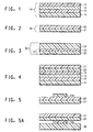
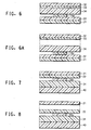
- the donor element comprises a thermally imageable layer (14) which is prepared from an aqueous dispersion comprising an immiscible compound and a polymeric dispersant.
- the donor element further comprises a base element having a layer with a coatable surface.
- the donor element comprises an intermediate layer (12) a heating layer (13)and a donor support (11).
- the heating layer (13) is located directly on the support (11).
- the donor support is a thick (16.06 mm) (400 guage) coextruded polyethylene terephthalate film.
- the donor support is a polyester film, specifically polyethylene terephthalate that has usually been plasma treated to accept the heating layer.
- an intermediate layer is usually not provided on the donor support.
- Backing layers may optionally be provided on the side of the donor support opposite the side of the support with the thermally imageable layer. These backing layers may contain fillers to provide a roughened surface on the back side of the donor support.
- the donor support itself may contain fillers, such as silica, to provide a roughened surface on the back surface of the support.
- the optional intermediate layer (12), as shown in Figure 1 is the layer that may provide additional force to effect transfer of the thermally imageable layer to the receiver element in the exposed areas.
- the intermediate layer should be capable of transmitting the laser radiation, and not be adversely affected by this radiation.
- the intermediate layer may be an ejection layer which, when heated, decomposes into gaseous molecules providing the necessary pressure to propel or eject the exposed areas of the thermally imageable layer onto the receiver element.
- a polymer having a relatively low decomposition temperature less than 350°C, preferably less than 325°C, and more preferably less than 280°C.
- the first decomposition temperature should be lower than 350°C.
- the ejection layer is flexible.
- the ejection layer In order for the ejection layer to have suitably high flexibility and conformability, it should have a tensile modulus that is less than or equal to 2.5 Gigapascals (GPa), preferably less than 1.5 GPa, and more preferably less than 1 GPa. It has been found beneficial if the polymer chosen is dimensionally stable.
- GPa 2.5 Gigapascals
- suitable polymers include (a) polycarbonates having low decomposition temperatures (Td), such as polypropylene carbonate; (b) substituted styrene polymers having low decomposition temperatures, such as poly(alpha-methylstyrene); (c) polyacrylate and polymethacrylate esters, such as polymethylmethacrylate and polybutylmethacrylate; (d) cellulosic materials having low decomposition temperatures (Td), such as cellulose acetate butyrate and nitrocellulose; and (e) other polymers such as polyvinyl chloride; poly(chlorovinyl chloride) polyacetals; polyvinylidene chloride; polyurethanes with low Td; polyesters; polyorthoesters; acrylonitrile and substituted acrylonitrile polymers; maleic acid resins; and copolymers of the above.
- Td polycarbonates having low decomposition temperatures
- Td polypropylene carbonate
- Polymers having low decomposition temperatures can also be used. Additional examples of polymers having low decomposition temperatures can be found in Foley et al., U.S. Patent No. 5,156,938 . These include polymers which undergo acid-catalyzed decomposition. For these polymers, it is frequently desirable to include one or more hydrogen donors with the polymer.
- Preferred polymers for the ejection layer are polyacrylate and polymethacrylate esters, low Td polycarbonates, nitrocellulose, poly(vinyl chloride) (PVC), and chlorinated poly(vinyl chloride) (CPVC). Most preferred are poly(vinyl chloride) and chlorinated poly(vinyl chloride).
- additives can be present as additives in the intermediate layer as long as they do not interfere with the essential function of the layer.
- additives include coating aids, flow additives, slip agents, antihalation agents, plasticizers, antistatic agents, surfactants, and others which are known to be used in the formulation of coatings.
- the intermediate layer may also be a subbing layer (12) to provide a donor element having in order at least one subbing layer (12), optionally, a heating layer (13), and at least one thermally imageable layer(14).
- the intermediate layer is a subbing layer
- it is characterized by an ability to adhere to an adjacent layer of the donor element, such as the heating layer or the support.
- suitable materials for the subbing layer include polyurethanes, polyvinyl chloride; cellulosic materials, acrylate or methacrylate homopolymers and copolymers, and mixtures thereof.
- Other custom made decomposable polymers may also be useful in the subbing layer.
- subbing layers for polyester, specifically polyethylene terephthalate are acrylic subbing layers.
- the subbing layer has a thickness of 100 to 1000 A (x10 -10 m).
- the optional heating layer (13) of the base element is deposited on the optional intermediate layer (12). More typically, the heating layer (13) is deposited directly on the support (11).
- the function of the heating layer is to absorb the laser radiation and convert the radiation into heat.
- Materials suitable for the heating layer can be inorganic or organic and can inherently absorb the laser radiation or include additional laser-radiation absorbing compounds.
- suitable inorganic materials are transition metal elements and metallic elements of Groups IIIA, IVA, VA, VIA, VIIIA, IIIB, and VB, their alloys with each other, and their alloys with the elements of Groups IA and IIA of the Periodic Table of the Elements (IUPAC) and oxides.
- Tungsten (W) is an example of a Group VIA metal that is suitable and which can be utilized.
- Carbon (a Group IVB nonmetallic element) can also be used.
- Preferred metals include Al, Cr, Sb, Ti, Bi, Zr, TiO2, Ni, In, Zn, and their alloys; carbon is a preferred nonmetal. More preferred metals and nonmetals include Al, Ni, Cr, Zr and C. Most preferred metals are Al, Ni, Cr, and Zr.
- An oxide found to be useful is TiO 2 .
- the thickness of the heating layer is generally 20 x10 -10 m (Angstroms) to 0.1 micrometer, preferably 40 to 100 x10 -10 m (Angstroms).
- the different layers can have the same or different compositions, as long as they all function as described above.
- the total thickness of all the heating layers should be in the range given above, i.e., 20 x 10 -10 m (Angstroms) to 0.1 micrometer.
- the heating layer(s) can be applied using any of the well-known techniques for providing thin metal layers, such as sputtering, chemical vapor deposition, and electron beam.
- the thermally imageable layer (14) of the donor element is formed by applying a coating composition, typically, containing colorant, to a surface of the base element of the donor element.
- a film forming ingredient which is a binder, can be added to the composition of the thermally imageable layer.
- the dispersant will also function as a binder and therefore avoid the need for an additional ingredient to function as a binder. However, this may not always be the case so a separate binder might be required if the dispersant alone does not adequately serve as a binder.
- the binder for the thermally imageable layer is usually a polymeric material having a decomposition temperature that is greater than 300°C and preferably greater than 350°C.
- the binder should be film forming and coatable from solution or from a dispersion. Binders having melting points less than 250°C or plasticized to such an extent that the glass transition temperature is less than 70°C are preferred.
- heat-fusible binders, such as waxes should be avoided as the sole binder since such binders may not be as durable, although they are useful as cobinders in decreasing the melting point of the top layer.
- the binder does not self-oxidize, decompose or degrade at the temperature achieved during the laser exposure so that the exposed areas of the thermally imageable layer comprising a colorant and a binder, are transferred intact for improved durability.
- the binder comprises a monomer which is an alkyl acrylate, alkyl methacrylate, acrylic acid or methacrylic acid, acrylonitrile or styrene.
- the alkyl groups contains 1 to 6 carbon atoms.
- alkyl groups include methyl, ethyl and n-butyl.
- the alkyl group contains one or more heteroatoms.
- a typical heteroatom is oxygen.
- the alkyl group can contain a hydroxy or epoxy substituent.
- Suitable binders include copolymers of styrene and (meth)acrylate esters, such as styrene/methacrylate copolymer, styrene/methyl-methacrylate copolymer; copolymer of styrene and olefin monomer, typically containing 1 to 4 carbon atoms, such as styrene/ethylene/butylene; copolymers of styrene and acrylonitrile; fluoropolymers; copolymers of (meth)acrylate esters with ethylene and carbon monoxide; polycarbonates having decomposition temperatures higher than 300°C, typically 280°C; (meth)acrylate homopolymers and copolymers; polysulfones; polyurethanes; polyesters.
- the monomers for the above polymers can be substituted or unsubstituted. Mixtures of polymers can also be used.
- An example is a copolymer comprising styrene; methyl methacrylate, butyl acrylate, methacrylic acid and glycedol methacryate or a copolymer comprising styrene, methyl methacrylate, methacrylic acid and glycedol methacrylate.
- Preferred binder compositions for the thermally imageable layer include, but are not limited to, acrylate homopolymers and copolymers, methacrylate homopolymers and copolymers, (meth)acrylate block copolymers, and (meth)acrylate copolymers containing other comonomer types, such as styrene.
- Specific examples include butyl acrylate/methyl acrylate/acrylic acid; styrene/methyl methacrylate/butyl acrylate/methacrylic acid and glycedol methacrylate polymers.
- a plasticizer may also be included which, typically is a low glass transition temperature polymer, that acts as a softener when the polymer of the binder has a high glass transition temperature.
- a suitable plasticizer is polyethylene glycol.
- the binder generally has a concentration of 15 to 50% by weight, based on the total weight of the thermally imageable layer, typically 30 to 40% by weight based on the total weight of the thermally imageable layer.
- the colorant of the thermally imageable layer can be a pigment or a dye, typically a non-sublimable dye.
- pigments are used as the colorant for stability and for color density, and also for the high decomposition temperature.
- suitable inorganic pigments include carbon black and graphite.
- suitable organic pigments include Rubine F6B (C.I. No. Pigment 184); Cromophthal ® Yellow 3G (C.I. No. Pigment Yellow 93); Hostaperm ® Yellow 3G (C.I. No. Pigment Yellow 154); Monastral® Violet R (C.I. No.
- Pigment Violet 19 2,9-dimethylquinacridone (C.I. No. Pigment Red 122); Indofast ® Brilliant Scarlet R6300 (C.I. No. Pigment Red 123); Quindo Magenta RV 6803; Monastral® Blue G (C.I. No. Pigment Blue 15); Monastral® Blue BT 383D (C.I. No. Pigment Blue 15); Monastral® Blue G BT 284D (C.I. No. Pigment Blue 15); and Monastral® Green GT 751D (C.I. No. Pigment Green 7).
- Combinations of pigments and/or dyes can also be used.
- high transparency pigments that is at least 80% of light transmits through the pigment
- having small particle size that is about 100 nanometers.
- a pigment such as carbon black
- This type of pigment functions as both a heat absorber and a colorant, and thus provides a dual function of being both a heating layer and a thermally imageable layer.
- the characteristics are the same as those for the thermally imageable layer.
- a preferred pigment which funtions as colorant and heat absorber is carbon black.
- the pigment and the immiscible compound are dispersed separately then combined together alternatively they are combined and then dispersed. Preparing separate dispersions has the advantage of allowing different concentrations to be used.
- the concentration of colorant will be chosen to achieve the optical density desired in the final image.
- the amount of colorant will depend on the thickness of the active coating and the absorption of the colorant. Optical densities of any suitable value, usually greater than 0.2, at the wavelength of maximum absorption are typical. Sometimes, high optical densities, e.g. greater than 3.0 are preferred. Optical densities adequate for a particular application can be achievable with this invention.
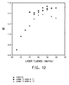
- Advantages of the invention in color proofing processes include broad sensitivity over a desirable laser power range (e.g., 12 to 18 watts), high resolution as evidenced by the holding of 1 pixel checker board patterns (10 micrometers by 10 micrometers), excellent overprints whereby uniform color blends are achieved with multicolor images (e.g., red and yellow layered to produce a uniform orange color lacking yellow or red stripes or spots) and minimal to no border solid tearing; that is, transfer of two adjacent solid colors result in a clean line between the colors as opposed to a ragged or rough line at the color boundary.
- a desirable laser power range e.g., 12 to 18 watts
- 1 pixel checker board patterns 10 micrometers by 10 micrometers
- excellent overprints whereby uniform color blends are achieved with multicolor images (e.g., red and yellow layered to produce a uniform orange color lacking yellow or red stripes or spots) and minimal to no border solid tearing; that is, transfer of two adjacent solid colors result in a clean line between the colors as
- a dispersant is usually present when employing pigment colorants.
- the colorant dispersant achieves maximum color strength, transparency and gloss.
- the colorant dispersant may be the same or different from that used to disperse the immiscible compound.
- the colorant dispersant is generally an organic polymeric compound and is used to separate the fine pigment particles and avoid flocculation and agglomeration.
- a wide range of colorant dispersants are commercially available.
- a colorant dispersant will be selected according to the characteristics of the pigment surface and other components in the composition as practiced by those skilled in the art. However, one class of colorant dispersant suitable for practicing the invention is that of the AB dispersants.
- the A segment of the dispersant adsorbs onto the surface of the pigment.
- the B segment extends into the solvent into which the pigment is dispersed.
- the B segment provides a barrier between pigment particles to counteract the attractive forces of the particles, and thus to prevent agglomeration.
- the B segment should have good compatibility with the solvent used.
- the AB dispersants of choice are generally described in U.S. 5,085,698 .
- Conventional pigment dispersing techniques, such as ball milling, sand milling, etc., can be employed.
- the colorant is usually present in an amount of from 25 to 95% by weight, typically 35 to 65% by weight, based on the total weight of the thermally imageable layer.
- any suitable solvent can be used as a coating solvent for the thermally imageable layer, as long as it does not deleteriously affect the properties of the assemblage.
- the layer is applied to the base element of the donor element using conventional coating techniques or printing techniques, for example, graver printing.
- a preferred solvent is water.
- the thermally imageable layer may also be applied using the WATERPROOF® Color Versatility Coater sold by DuPont, Wilmington, DE. The thermally imageable layer can thus be applied shortly before the exposure step. This also allows for the mixing of various basic colors together to fabricate a wide variety of colors to match the Pantene ® color guide currently used as one of the standards in the proofing industry.
- the thermally imageable layer generally has a thickness in the range of 0.1 to 5 micrometers, preferably in the range of 0.1 to 1.5 micrometers. Thickness greater than 5 micrometers are generally not preferred as they require excessive energy in order to be effectively transferred to the receiver.
- thermally imageable layer Although it is preferred to have a single thermally imageable layer, it is also possible to have more than one thermally imageable layer, and the different layers can have the same or different compositions, as long as they all function as described above.
- the total thickness of the combined thermally imageable layers should be in the range given above.
- additives can be present as additives in the thermally imageable layer as long as they do not interfere with the essential function of the layer.
- additives include coating aids, plasticizers, flow additives, slip agents, antihalation agents, antistatic agents, surfactants, and others which are known to be used in the formulation of coatings.
- coating aids plasticizers
- flow additives slip agents
- antihalation agents antistatic agents
- surfactants surfactants
- Additives may add impart unwanted color are usually avoided for color proofing applications as well as those additives that tend to decrease durability and print life in lithographic printing applications. With the instant invention, immiscible additives can be used.
- the donor element may have additional layers (not shown) as well.
- an antihalation layer may be used on the side of the optional intermediate layer opposite the thermally imageable layer. Materials which can be used as antihalation agents are well known in the art. Other anchoring or subbing layers can be present on either side of the intermediate layer and are also well known in the art.
- the donor element can be used for color filters for use in liquid crystal display (LCD) devices.
- LCD liquid crystal display
- a dye or pigment is present in the thermally imageable layer of the donor element, typically, the donor element contains a cross-linkable polymer.
- a cross-linkable polymer can also be used in the image receiving layer.
- the dispersant may be crosslinkable.
- a cross-linkable polymer typically, 1-5 mol-% of a cross-linkable monomer is incorporated into the polymeric binders of the instant invention. After crosslinking, the binders exhibit resistance to the temperatures and solvents employed in the formation of color filter arrays in liquid crystal display devices, making this embodiment highly useful in that application.
- Suitable cross-linkable comonomers include but are not limited to hydroxy ethyl methacrylate and glycidyl methacrylate.
- one or more of the polymeric binders may comprise monomer units having pendant groups which are capable of undergoing free-radical induced or cationic crosslinking reactions.
- Pendant groups which are capable of undergoing free-radical induced crosslinking reactions are generally those which contain sites of ethylenic unsaturation, such as mono- and polyunsaturated alkyl groups; acrylic and methacrylic acids and esters.
- the pendant crosslinking group can be photosensitive, as is the case with pendant cinnamoyl or N-alkyl stilbazolium groups.
- Pendant groups which are capable of undergoing cationic crosslinking reactions include substituted and unsubstituted epoxide and aziridine groups.
- Cross-linkable binders suitable for the practice of the invention can be formed by direct copolymerization of one or more ethylenically unsaturated dicarboxylic acid anhydrides, or the corresponding alkyl diesters, with one or more of the above comonomers.
- Suitable ethylenically unsaturated dicarboxylic acid anhydrides are, for example, maleic anhydride, itaconic acid anhydride and citraconic acid anhydride and alkyl diesters such as the diisobutyl ester of maleic anhydride.
- the copolymer binder containing acid anhydride functionality can be reacted with primary aliphatic or aromatic amines.
- the dye and/or pigment(s) for color filter applications are chosen such that optical densities on the receiver element in areas where material has been transferred are preferably between 1.0 and 2.0 for red, blue and green, and between 3.0 and 4.0 for black.
- the dye and/or pigment(s) are present in an amount of from 20 to 80% by weight, more typically 30 to 50% by weight, based on the total weight of the transfer coating.
- a liquid crystal display device consists of a liquid crystal layer with opposite sides, a set of electrodes on either side of the liquid crystal layer, and an alignment polymer layer between each set of electrodes and the liquid crystal layer. Alignment of the liquid crystal molecules occurs at a certain angle, referred to as the tilt angle, with respect to the plane of the inside of two substrates, e.g., glass plates, plastic sheets, quartz plates, or others which support the electrodes.
- the inside of the substrates have coatings of sets of transparent electrodes (electrical conductors), usually indium-tin oxide (ITO).
- ITO indium-tin oxide
- the sets of electrodes are patterned compatible with the information to be displayed by the LCD.
- the two substrates are adhered together using appropriate spacers to preserve a constant thickness to a space or gap between substrate, and filled with various mixtures of liquid crystal materials.
- color filter array element is included on the outside of one of the two substrates which support the electrodes prior to forming the LCD device.
- the color filter array to be used therein may have to undergo rather severe heating and treatment steps during manufacture.
- the transparent conducting layer such as ITO
- ITO is usually vacuum sputtered onto the substrate having the color filter array element which is then cured. This curing step may take place at temperatures as high as 250°C for times which may be as long as an hour.
- This is followed by coating with the thin polymeric alignment layer for the liquid crystals, such as polyamide.
- the surface finish of the alignment layer may require rubbing or may require curing for up to several hours at elevated temperatures.
- the color filter layer on the substrate is capable of surviving the subsequent processing steps associated with the formation of the LCD device.
- the dye or pigment is present in the thermally imageable layer.
- the thermally imageable layer can be such that optical densities on the receiver element in areas where material has been transferred are preferably between 1.0 and 2.0 for red, blue and green, and between 3.0 and 4.0 for black.
- the receiver element can be different from the receiver element used in color proofing.
- the receiver element can include the permanent substrate such as a glass substrate optionally with an image-receiving layer, and polarizing filter elements and flexible glass.
- the receiver element can be an intermediate element onto which a multicolor image in which the additive primary colors (red, green, and blue) are formed into a mosaic pattern in a black matrix.
- the color image can then be transferred, for example by lamination, to a receptor element such as, for example, a flexible glass substrate or a polarizing filter element associated with the LCD device.
- the glass substrate may optionally have one or more layers to receive and adhere the color image layer to glass. Examples of materials which are suitable to receive the color image to the glass substrate include ethylene copolymers, adhesion promotors, and UV crosslinkable adhesives.
- a particularly suitable polarizing filter element is one which is used for thin film transistor (TFT) color filters.
- the color image on the receiver element (which is an intermediate receiver element) can then be transferred for example by lamination to a receptor element of a flexible glass substrate or polarizing filter element of an LCD device for color filter array applications. After lamination, the intermediate receiver element is separated from the permanent receptor, to complete the transfer of the color image. Upon separation, the image receiving layer may remain with the color filter on the LCD.
- the image receiving layer can then act as a planarizing layer to provide a substantially planar layer on the outer surface of the LCD device and thereby obscure any nonuniformities in the thickness of the color filter layer.
- Other donor elements may comprise additional thermally imageable layer or layers on a support. Additional layers may be present depending of the specific process used for imagewise exposure and transfer of the formed images.
- Some suitable donor elements are disclosed in U.S. 5,773,188 , U.S. 5,622,795 , U.S. 5,593,808 , U.S. 5,334,573 , U.S. 5,156,938 , U.S. 5,256,506 , U.S. 5,427,847 , U.S. 5,171,650 and U.S. 5,681,681 .
- the receiver element (20), shown in Figure 2 is the second part of the laserable assemblage, to which the exposed areas of the thermally imageable layer are transferred.
- the exposed areas of the thermally imageable layer will not be removed from the donor element in the absence of a receiver element. That is, exposure of the donor element alone to laser radiation does not cause material to be removed, or transferred.
- the exposed areas of the thermally imageable layer are removed from the donor element only when it is exposed to laser radiation and the donor element is in contact with or adjacent to the receiver element. Typically, the donor element actually touches the receiver element.
- the surface of the donor element or the receiver and/or both may be roughened to improve contact between the two elements.
- the receiver element (20) may be non-photosensitive or photosensitive.
- the receiver element when the receiver element is non-photosensitive, preferably, it comprises a receiver support (21) and at least one image receiving layer (22).
- the receiver support (21) comprises a dimensionally stable sheet material:
- the assemblage can be imaged through the receiver support if that support is a transparent material.
- transparent materials typically include transparent films, for example polyethylene terephthalate, polyether sulfone, a polyimide; a poly(vinyl alcohol-co-acetal), polyethylene, or a cellulose ester, such as cellulose acetate.
- opaque support materials include, for example, polyethylene terephthalate filled with a white pigment such as titanium dioxide, ivory paper, or synthetic paper, such as Tyvek ® spunbonded polyolefin. Paper supports are typical and are preferred for proofing applications, while a polyester support, such as poly(ethylene terephthalate) is typical and is preferred for a medical hardcopy and color filter array applications. Supports which have a roughened surface may also be used in the receiver element.
- the image-receiving layer (22) may be a coating of, for example, a polycarbonate; a polyurethane; a polyester; polyvinyl chloride; styrene/acrylonitrile copolymer; poly(caprolactone); vinylacetate copolymers with ethylene and/or vinyl chloride; (meth)acrylate homopolymers (such as butyl-methacrylate) and copolymers, polycaprolactone; and mixtures thereof.
- a polycarbonate for example, a polycarbonate; a polyurethane; a polyester; polyvinyl chloride; styrene/acrylonitrile copolymer; poly(caprolactone); vinylacetate copolymers with ethylene and/or vinyl chloride; (meth)acrylate homopolymers (such as butyl-methacrylate) and copolymers, polycaprolactone; and mixtures thereof.
- the image receiving layer for the color proofing application may comprise two separate layers wherein the layer adjacent the receiver support is a vinyl acetate copolymer such as polyethylene/polyvinyl acetate and the outer layer comprises a polyester.
- the image receiving layer for the color proofing application may comprise two separate layers wherein the layer adjacent the receiver support is a vinyl acetate copolymer such as polyethylene/polyvinyl acetate and the outer layer comprises a polyester.
- Useful receiver elements are also disclosed in U.S. Patent No. 5,534,387 issued on July 9, 1996 .
- One preferred example is the WATERPROOF® Transfer Sheet sold by DuPont. Typically, it has an ethylene/vinyl acetate copolymer in the surface layer comprising more ethylene than the vinyl acetate.
- This image-receiving layer can be present in any amount effective for the intended purpose. In general, good results have been obtained at coating weights of range of 10 to 150 mg/dm 2 , more typically in the range of 40 to 60 mg/m 2 .
- the receiver element may optionally include one or more other layers (not shown) between the receiver support and the image receiving layer.
- One such additional layer between the image-receiving layer and the support is a release layer.
- the receiver support alone or the combination of receiver support and release layer may also be referred to as a first temporary carrier.
- the release layer can provide the desired adhesion balance to the receiver support so that the image-receiving layer adheres to the receiver support during exposure and separation from the donor element, but promotes the separation of the image receiving layer from the receiver support upon transfer, for example by lamination, of the image receiving layer to a permanent substrate or support.
- the release layer can have a thickness in the range of 1 to 50 micrometers.
- a cushion layer which is a deformable layer may also be present in the receiver element, typically between the release layer and the receiver support. The cushion layer may be present to increase the contact between the receiver element and the donor element when assembled.
- suitable materials for use as the cushion layer include polyesters, copolymers of styrene and olefin monomers such as styrene/ethylene/butylene/styrene, styrene/butylene/styrene block copolymers, and other elastomers useful as binders in flexographic plate applications.
- the receiver element may be an intermediate element in the process of the invention because the laser imaging step is normally followed by one or more transfer steps by which the exposed areas of the thermally imageable layer are transferred to the permanent substrate.
- the invention further comprises the steps of contacting the image on the image receiving layer of the receiver element with an image rigidification element comprising:
- an image receiving layer having an outer surface with a halftone dot thermal image applied thereto by imagewise exposure of a donor element comprising a thermally imageable layer of this invention; and an image rigidification layer having a first surface and a second surface, the outer surface of the image receiving layer being located on the first surface thereof and a final receptor located on the second surface thereof, whereby the image is encased between the image receiving layer and the image rigidification layer.
- the image rigidification element (30), shown in Figure 3 comprises a support (32) having a release surface (31), also referred to as a second temporary carrier, and an image rigidification layer (34) which serves to rigidify the image to hold it in place so that upon transfer to the final or temporary receptor, it does not shift which provides a clear image.
- the image rigidification layer also fixes the image so that it will not shift when another image is applied to the imaged surface of the receiver element.
- the support (32) of the image rigidification element may include a release surface (33). If the material used as the support, has a release surface, e.g., polyethylene or a fluoropolymer, no additional surface layer is needed.
- the release surface (33) should have sufficient adhesion to the support (32) to remain affixed to the support throughout the processing steps of the invention. Almost any material that has reasonable stiffness and dimensional stability is useful as the support.
- Some examples of useful supports include polymeric films such as polyesters, including polyethylene terephthalate and polyethylene naphthanate; polyamides; polycarbonates; fluoropolymers; polyacetals; polyolefins, etc.
- the support may also be a thin metal sheet or a natural or synthetic paper substrate.
- the support may be transparent, translucent or opaque. It may be colored and may have incorporated therein additives such as fillers to aid in the movement of the image rigidification element through the lamination device during its lamination to the imaged receiver element.
- the support may have antistatic layers coated on one or both sides for reducing static when the support is removed from the image rigidification layer during the process of the invention. It is generally preferred to have antistatic layers coated on the back side of the support, i.e., the side of the support away from the image rigidification layer. Materials which can be used as antistatic materials are well known in the art.
- the support may also have a matte texture to aid in transport and handling of the image rigidification element.
- the support of the image rigidification element typically has a thickness of 20 ⁇ m to 250 ⁇ m.
- a preferred thickness is 55 to 200 ⁇ m.
- the release surface of the support is generally a very thin layer which promotes the separation of the support from the image rigidification layer.
- Materials useful as release layers are well known in the art and include, for example, silicones; melamine acrylic resins; vinyl chloride polymers and copolymers; vinyl acetate polymers and copolymers; plasticized polyvinyl alcohols; ethylene and propylene polymers and copolymers; etc.
- the layer When a separate release layer is coated onto the support, the layer generally has a thickness in the range of 0.5 to 10 micrometers.
- the release surface (33) may also include materials such as antistats, colorants, antihalation dyes, optical brighteners, surfactants, plasticizers, coating aids, matting agents, and the like.
- thermoplastic polymers useful as the image rigidification layer (34) are preferably amorphous, i.e., non-crystalline, in character, have high softening points, moderate to high molecular weight and compatibility with the components of the image receiving polymer layer, e.g., polycaprolactone. Additionally, flexibility without cracking and possessing the capability to be attached to many different permanent substrates is advantageous.
- the polymer is preferably solvent soluble, has good solvent and light stability and is a good film former.
- thermoplastic polymer materials which can be used as the image rigidification layer.
- Preferred for use in this invention are thermoplastic polymers having Tgs (glass transition temperatures) in the range of 27 to 150°C, preferably 40 to 70°C, and more preferably 45 to 55°C, a relatively high softening points, e.g., Tg of 47°C, melt flow of 142°C).
- Tgs glass transition temperatures
- Other useful characteristics include a low elongation at break as determined by ASTM D822A, an elongation at break of 3 has been effective, and moderate weight average molecular weight (Mw), e.g., in the area of 67,000.
- Polyester polymers e.g., having a Tg of 47°C, are preferred because good compatibility is achieved between the image receiving polymer, e.g., crystalline polycaprolactone, and the polyester polymer in the image rigidification layer.
- image receiving polymer e.g., crystalline polycaprolactone
- suitable polymers have been shown to give acceptable results.
- Some suitable materials include methacrylate/acrylate, polyvinylacetate, polyvinylbutyral, polyvinylformal, styrene-isopiene-styrene and styrene-ethylene-butylene-styrene polymers, etc.
- thermoplastic polymer is present in the amount of 60 to 90%, preferably 70 to 85%, based on the total weight of the image rigidification layer.
- the image rigidification layer and image receiving layer relate to each other in that the colored image is encased between them so that it does not move significantly during lamination to the permanent substrate, e.g., paper, and cooling. This significantly reduces halftone dot movement, swath boundary cracking and banding compared to similar processes not employing a image rigidification layer in this manner, i.e., an image rigidification element, and renders these defects barely perceptible and even eliminated.
- the use of the image rigidification layer in the processes and products of this invention results in an increase in lamination throughput speeds from 200 mm/min to approximately 600 to -800 mm/min (3-4 fold increase) without the introduction of defects, and provides lamination process latitude to allow image transfer to many different types of permanent substrates.
- the image rigidification layer also provides a vehicle or mechanism for the introduction of bleaching chemistry to reduce the impact on final color associated with the NIR dye in the thermally imageable layer of the donor element to the permanent substrate.
- the image rigidification layer may also contain additives as long as they do not interfere with the functioning of this layer.
- additives such as plasticizers, other modifying polymers, coating aids, surfactants can be used.
- plasticizers include polyethylene glycols, polypropylene glycols, phthalate esters, dibutyl phthalate and glycerine derivatives such triacetin.
- the plasticizer is present in the amount of 1 to 20%, most preferably 5 to 15%, based on the total weight of the image rigidification layer. These plasticizers can be used in the thermally imageable layer.
- the image rigidification layer also preferably contains dye bleaching agents for bleaching the thermal amplification additive, such as an NIR dye, which may be present in the thermally imageable layer.
- dye bleaching agents include amines, azo compounds, carbonyl compounds and, organometallic compounds, carbanions, and hydantoins such as 1,3-dichloro-5,5-dimethyl hydantoin.
- Useful oxidants include peroxides, diacyl peroxides, peroxy acids, hydroperoxides, persulfates, and halogen compounds.
- Particularly useful dye bleaching agents with polymethine type NIR dyes are those selected from the group consisting of hydrogen peroxide, organic peroxides, hexaaryl biimidazoles, halogenated organic compounds, persulfates; perborates, perphosphates, hypochlorites; hydantoins and azo compounds. These bleaching agents may also be employed in the thermally imageable layer.
- Dye bleaching agents are present in the amount of 1 to 20%, preferably 5 to 15%, based on the total weight of the image rigidification layer.
- the permanent substrate for receiving the image
- the permanent substrate can be selected from almost any sheet material desired.
- a paper is used, preferably the same paper on which the image will ultimately be printed.
- Most any paper stock can be used.
- Other materials which can be used as the permanent substrate include cloth, wood, glass, china, most polymeric films, synthetic papers, thin metal sheets or foils, etc. Almost any material which will adhere to the image rigidification layer (34), can be used as the permanent substrate.
- the first step in the process of the invention is imagewise exposing the laserable assemblage, e.g., as shown in Figure 4 , to laser radiation.
- the exposure step is preferably effected at a laser fluence of 600 mJ/cm 2 or less, most preferably 250 to 440 mJ/cm 2 .
- the laserable assemblage comprises the donor element (10)and the receiver element (20).
- the assemblage is prepared following removal of coversheet(s), if present, by placing the donor element (10) in contact with the receiver element (20) such that the thermally imageable layer (14) actually contacts the image-receiving layer (22) of the receiver element.
- Vacuum and/or pressure can be used to hold the donor and receiver elements together.
- the donor and receiver elements may be spaced slightly apart using spacer particles in the thermally imageable layer or the image receiving layer.
- the surfaces of the donor and/or receiver elements that are adjacent each other may be roughened, e.g., by embossing.
- the donor and receiver elements can be held together by fusion of layers at the periphery.
- the donor and receiver elements can be taped together and taped to the imaging apparatus, or a pin/clamping system can be used.
- the donor element can be laminated to the receiver element to afford a laserable assemblage.
- the laserable assemblage can be conveniently mounted on a drum to facilitate laser imaging.
- the laser is preferably one emitting in the infrared, near-infrared or visible region. Particularly advantageous are diode lasers emitting in the region of 750 to 870 nm which offer a substantial advantage in terms of their small size, low cost, stability, reliability, ruggedness and ease of modulation. Diode lasers emitting in the range of 780 to 850 nm are most preferred. Such lasers are available from, for example, Spectra Diode Laboratories (San Jose, CA).
- the exposure can take place through the optional intermediate layer of the donor element, if present, the thermally imageable layer of the donor element, or through the receiver element, provided that these are substantially transparent to the laser radiation.
- the intermediate layer will be a film which is transparent to infrared radiation and the exposure is conveniently carried out through the intermediate layer.
- the process of the invention can also be carried out by imagewise exposing the receiver element to infrared laser radiation.
- the laserable assemblage is exposed imagewise so that the exposed areas of the thermally imageable layer are transferred to the receiver element in a pattern.
- the pattern itself can be, for example, in the form of dots or line work generated by a computer, in a form obtained by scanning artwork to be copied, in the form of a digitized image taken from original artwork, or a combination of any of these forms which can be electronically combined on a computer prior to laser exposure.
- the laser beam and the laserable assemblage are in constant motion with respect to each other, such that each minute area of the assemblage, i.e., "pixel" is individually addressed by the laser. This is generally accomplished by mounting the laserable assemblage on a rotatable drum.
- a flat bed recorder can also be used.
- the next step in the process of the invention is separating the donor element from the receiver element. Usually this is done by simply peeling the two elements apart. This generally requires very little peel force, and is accomplished by simply separating the donor support from the receiver element. This can be done using any conventional separation technique and can be manual or automatic without operator intervention.
- separation results in a laser generated color image, also known as the colored image, preferably a halftone dot image, comprising the transferred exposed areas of the thermally imageable layer being revealed on the image receiving layer of the receiver element.
- the image formed by the exposure and separation steps is a laser generated halftone dot color image formed on an image receiving layer.
- this image may then be laminated to the permanent substrate (40), and the transfer support (21) peeled off to transfer the image (14a) and the image receiving layer (22) to the permanent substrate (40).
- the image rigidification element (30) may then be brought into contact with, typically laminated to, the image receiver element (20) with the colored image (14a) in contact with the image rigidification layer (34) of the image rigidification element (30) resulting in the image rigidification layer (34) of the rigidification element and the image receiving layer (22) of the receiver element encasing the color image.
- a WATERPROOF® Laminator, manufactured by DuPont is preferably used to accomplish the lamination.
- other conventional means may be used to accomplish contact of the image carrying receiver element with the image rigidification layer of the image rigidification element.
- the assemblage shown in Figure 6 is highly useful, e.g., as an improved image proofing system.
- the support (32) is then removed, typically by peeling off, to reveal the thermoplastic film as seen in Figure 6a .
- the image on the receiver element is then transferred to the permanent substrate by contacting the permanent substrate with, preferably laminating it to, the revealed image rigidification layer of the assemblage shown in Figure 6a .
- a WATERPROOF® Laminator manufactured by DuPont, is preferably used to accomplish the lamination.
- other conventional means may be used to accomplish this contact which results in the assemblage shown in Figure 7 .
- Another embodiment includes the additional step of removing, typically by peeling off, the receiver support (21) (also known as the first temporary carrier), resulting in the assemblage shown in Figure 8 .
- the assemblages illustrated in Figures 7 and 8 represent a printing proof comprising a laser generated halftone dot color thermal image formed on an image receiving layer such as a polyester layer, and an image rigidification layer laminated on one surface to said image receiving layer and laminated on the other surface to the permanent substrate, whereby the image is encased between the image receiving layer and the image rigidification layer.
- an image receiving layer such as a polyester layer
- an image rigidification layer laminated on one surface to said image receiving layer and laminated on the other surface to the permanent substrate, whereby the image is encased between the image receiving layer and the image rigidification layer.
- the receiver element can be an intermediate element onto which a multilayer or multicolor image is built up.
- a colorant can be substituted for an immiscible compound.
- a donor element having a thermally imageable layer comprising a first colorant is exposed and separated as described above.
- the receiver element has an image formed with the first colorant, which is preferably a laser generated halftone dot color thermal image.
- a second donor element having a thermally imageable layer different than that of the first donor element forms a laserable assemblage with the receiver element having the image of the first donor element and is imagewise exposed and separated as described above.
- the rigidification element may then be brought into contact with, typically laminated to, the multiple colored images on the image receiver element with the last colored image in contact with the image rigidification layer. The process is then completed as described above.
- the dispersion in Table 1 was prepared by mixing together 16.67 gms. of a 60% dispersant solution in isopropanol, 60.07 gms. of water and 3.26 gr. of 50% 2-amino-2-methyl-1-propanol in water. 20 gms. of TIC/5C dye were added to this mixture. The mixture was run at 5000 rpm for 60 minutes on an Omni Mixer. The resultant dispersion could be easily re-dispersed with shaking if it settled. When the aqueous dispersion of TIC/5C described above was introduced in color filters and color proofing type formulations at 2% concentration, the optical absorption at 850 nm was 1.6.
- the dispersion in Table 2 was prepared by mixing together 2.5 gms. of a 60% dispersant solution in isopropanol, 9.011 gms. of water and 0.489 gms. of 50% 2-amino-2-methyl-1-propanol in water. 3 gms. of ADS 830 absorber were added to this mixture. The mixture was run at 7500 rpm for 60 minutes on an Omni Mixer. The resultant dispersion could be easily redispersed with shaking if it settled.
- a receiver element was prepared by coating CAPA650, polycaprolactone on a Mylar ® substrate.
- This example shows the use of TIC/5C dye dispersion in a yellow pigmented layer of a donor element and the use of this element in a color proofing application.
- Six sample donor elements and a control were prepared. Each donor element comprises a 4 mil polyester backing (Melinex ® 574) sputtered with about 70 x10 -10 m ( ⁇ ) of chromium by Vacuum Deposit Inc. (Louisville, KY). The metal thickness was monitored in situ using a quartz crystal and after deposition by measuring reflection and transmission of the films.
- Thermally imageable layers prepared from the control composition and 6 sample compositions specified in Table 3 were hand coated on the chromium layer using DuPont's WATERPROOF Color Versatility coater and a wire rod #6, followed by drying at 50°C for 5 minutes.
- Each of the so prepared yellow donor elements and receiver element prepared as described above were placed in the cassette of a Creo 3244 Spectrum Trendsetter, Creo, Vancouver, BC, and imaged under the following conditions: yellow (13.0 watts, 100 and 200 rpm).
- the computer attached to the Trendsetter contained digital data files representing the 4 process colors (yellow, magenta, cyan and black).
- This imaging equipment produced a laser generated yellow color thermal digital halftone image (proof) in reverse reading form on the Receiver Element from the digital image data file representing yellow. Exposure was effected at a laser fluence of about 250 mJ/cm 2 .
- the color image formed was then transferred to a LOE paper substrate.
- the image was transferred to an image rigidification element comprising Vitel ® 2700B polyester containing layer on a silicone release Mylar ® substrate.
- the receiver support was peeled off and the image was contacted with an LOE paper substrate followed by peeling off of the image rigidification element support to form an image on the LOE paper substrate sandwiched between the polycaprolactone layer and the Vitel ® 2700B polyester containing layer.
- Example 1 was repeated with the following exceptions: the thermally imageable layers were prepared from cyan color compositions shown in Table 4. Imaging was accomplished under the following conditions: cyan (14.5 watts, 135 rpm). TABLE 4 Sample Control (C2) S7 S8 330D 4.79 2.55 2.55 FSA 0.15 0.075 0.075 DD1 0.525 0.525 RCP2 28.5 15.26 15.26 PEG 1.05 1.93 103 1.76 ADS-830 0.28 Water 62.6 29.652 29.83 Solution 100 50 50 Solids % 14.43 15 15 15
- Example 1 was repeated with the following exceptions: the thermally imageable layer were prepared from magenta color compositions shown in Table 5. Imaging for the control and samples S9 and S10 was accomplished under the following conditions: cyan (13.5 watts, 135 rpm). TABLE 5 Sample Control (C3) S9 S10 164 7.04 3.562 3.562 166 0.38 0.1875 0.1875 FSA 0.14 0.075 0.075 DD1 0.525 0.7 RCP 2 27.89 13.21 13.125 PEG 1.05 2.88 103 2.64 ADS-4297 0.28 Water 63.05 29.80 29.47 Solution 99.93 50 50 Solids gms 14.91 7.544 7.5575
- the plot of Figure 11 shows the broad laser power sensitivity range of 13 to 18 watts. A high resolution as evidenced by the holding of 1 pixel checkerboard patterns, excellent overprints throughout the range, and reduced Border Solid Tearing (BST) with none present at high laser powers was also found.
- BST Border Solid Tearing
- Example 1 was repeated with the following exceptions: the thermally imageable layers were prepared from yellow color compositions shown in Table 6 prepared from dispersions of SQS shown in Table 2. TABLE 6 Sample control 11 12 144D 4.19 2.23 2.23 145D 0.84 0.45 0.45 FSA 0.15 0.075 0.075 DD2 0.52 0.52 RCP2 28.33 15.16 15.16 PEG 1.05 1.89 103 1.70 SQS 0.28 Water 65.17 29.67 29.86 Solution 100 50 50 Solids % 14.08 15 15 15
- the plot of Figure 12 demonstrates the sensitivity of the coating compositions over the laser fluence of about 12 to about 20 watts.
- Example 1 was repeated with the following exceptions: the thermally imageable layers were prepared from compositions shown in Table 7 prepared from dispersions of TIC/5C shown in Table 1. TABLE 7 Sample Control (C5) S13 RD 30 30 111 7.24 7.24 FSA 0.0375 0.0375 DD1 0.52 103 1.278 1.278 ADS-830 0.15 Water 14.6 14.6 Solution 50 50 Solids % 15 15
- This example shows the use of water immiscible NIR dye, DF-1704, that is dispersed in neat form directly into a yellow donor composition, without the formation of a masterbatch.
- the water immiscible NIR dye was added to a polymer latex containing pigment.
- the latex binder identified as RCP3 to which the NIR dye of this example was added was made from a dispersion of the ingredients listed in Table 9a below.
- a sample donor element and a control were prepared from a dispersion of the ingredients listed in Table 9a, above.
- Each donor element comprises a 0.102 mm (4 mil) polyester backing (Melinex® 574, DuPont Teijin Films) sputtered with chromium at a transmittance of 60%.
- the thermally imageable coatings were hand coated on the chromium layer using a wire wound rod to a dried coating weight of approximately 6 mg/sq dm. Absorption spectra of each film showed the presence of incorporated dye.
- the films were imaged using the Creo 3244 Spectrum Trendsetter, Creo, Vancouver, BC, and imaged at 18 watts, 180 rpm, and 60 SD.
- the imaging equipment produced a laser generated yellow color image on a receiver element for both C6 and S 14.
- the color image formed was then transferred to an image rigidification element comprising Vitel® 2700B polyester on a silicone release Mylar® substrate.
- the receiver support was peeled off and the image was contacted with an LOE paper substrate followed by peeling off the image rigidification element support to form an image on LOE paper substrate sandwiched between the polycaprolactone layer and the Vitel® 2700B polyester containing layer.
- each imaged film on LOE paper was analyzed spectroscopically and found to possess characteristic NIR dye absorbance in the actinic region of 830-850 nm.
- Table 10 shows the reflectance data of solid images of each film on LOE paper in which the LOE paper served as a reference. The data shows that the immiscible dye, DF-1704, was successfully dispersed into the donor composition as evidenced by its absorption in the imaged proof.
- TABLE 10 Sample Pigment ⁇ max Pigment Absorbance at ⁇ max Dye ⁇ max Dye Absorbance at ⁇ max C6 430 nm 0.7 au 841 nm 0.17 au S14 430 nm 1.1 au 836 nm 0.46 au
Landscapes
- Physics & Mathematics (AREA)
- Optics & Photonics (AREA)
- Engineering & Computer Science (AREA)
- Manufacturing & Machinery (AREA)
- Thermal Transfer Or Thermal Recording In General (AREA)
Claims (12)
- Élément donneur comprenant une couche exposable thermiquement préparée à partir d'une dispersion aqueuse comprenant un additif d'amplification thermique non miscible et un dispersant dans lequel l'additif d'amplification thermique est un composé absorbant les IR qui est(a) 3-H-indolium,2-[2-[2-chloro-3-dihydro-1,3,3-triméthyl-2H-indol-2-ylidène)éthylidène]-1-cyclopentèn-1-yl]éthyényl]-1,3,3-triméthyl-, sel avec acide trifluorométhane sulfonique (1 :1) ;(b) 3H-indolium, 2-[2-[3-[(1,3-dihydro-1,3,3-triméthyl-2H-indol-2-ylidène)éthylidène]-2-(2-pyrimidinylthio)-1-cyclopentèn-1-yl]éthényl]-1,3,3-triméthyl-, sel avec acide trifluorométhane sulfonique (1 :1) ;(c) 2-(2-(2-chloro-3-(2-(1,3-dihydro-1,1-diméthyl-3-(4-sulfobutyl)-2H-benz[e]indol-2-ylidène) éthylidène)-1-cyclohexène-1-yl)éthényl)-1,1-diméthyl-3-(4-sulfobutyl)-1H-benz[e]indolium, sel interne, acide libre ; ou(d) thiopyrylium,4-((3-((2,6-bis(1,1-dimémyléthyl)-4H-thiopyran-4-ylidène)méthyl)-2-hydroxy-4-oxo-2-cyclobutèn-1-ylidène)méthyl)-2,6-bis(1,1-diméthyléthyl)-, sel interne.
- Élément donneur selon la revendication 1, dans lequel le dispersant comprend un monomère qui est un acrylate d'alkyle, un méthacrylate d'alkyle, l'acide acrylique, l'acide méthacrylique ou un styrène, le groupe alkyle contenant 1 à 6 atomes de carbone.
- Élément donneur selon la revendication 1, dans lequel le dispersant est (a) un polymère greffé avec un squelette comprenant un polymère acrylique avec des bras de polymère acrylique dans lequel le squelette est un copolymère d'un ou plusieurs acrylates et d'acide acrylique au moins un bras est un copolymère d'un acrylate et d'acide acrylique, (b) un copolymère de styrène et de méthacrylate ou (c) un copolymère de méthacrylate de méthyle et de n-butylméthacrylate.
- Élément donneur selon la revendication 1, dans lequel la couche exposable thermiquement comprend en outre un polymère qui est réticulable.
- Élément donneur selon la revendication 1, qui est pour un filtre de couleur.
- Procédé pour faire une image comprenant :(1) une exposition en fonction de l'image à un rayonnement laser d'un assemblage compatible laser comprenant :(A) un élément donneur comprenant une couche exposable thermiquement préparée à partir d'une dispersion aqueuse comprenant un additif d'amplification thermique non miscible et un dispersant dans lequel l'additif d'amplification thermique est un composé absorbant les IR qui est(a) 3-H-indolium,2-[2-[2-chloro-3-dihydro-1,3,3-triméthyl-2H-indol-2-ylidène)éthylidène]-1-cyclopentèn-1-yl]éthyényl]-1,3,3-triméthyl-, sel avec acide trifluorométhane sulfonique (1 :1) ;(b) 3H-indolium, 2-[2-[3-((1,3-dihydro-1,3,3-triméthyl-2H-indol-2-ylidène)éthylidène]-2-(2-pyrimidinylthio)-1-cyclopentèn-1-yl]éthényl]-1,3,3-triméthyl-, sel avec acide trifluorométhane sulfonique (1 :1) ;(c) 2-(2-(2-chloro-3-(2-(1,3-dihydro-1,1-diméthyl-3-(4-sulfobutyl)-2H-benz[e]indol-2-ylidène) éthylidène)-1-cyclohexène-1-yl)éthényl)-1,1-diméthyl-3-(4-sulfobutyl)-1H-benz[e]indolium, sel interne, acide libre ;ou(d) thiopyrylium,4-((3-((2,6-bis(1,1-dimémyléthyl)-4H-thiopyran-4-ylidène)méthyl)-2-hydroxy-4-oxo-2-cyclobutèn-1-ylidène)méthyl)-2,6-bis(1,1-diméthyléthyl)-, sel interne ;et(B) un élément récepteur en contact avec la couche exposable thermiquement de l'élément donneur ; l'élément récepteur comprenant :moyennant quoi les zones exposées de la couche exposable thermiquement sont transférées sur l'élément récepteur de façon à former une image sur la couche de réception d'image ;(a) une couche de réception d'image ; et(b) un support récepteur ;(2) séparer l'élément donneur (A) de l'élément récepteur (B), en révélant de ce fait l'image sur la couche de réception d'image de l'élément récepteur ;(3) mettre en contact l'image révélée sur la couche de réception d'image de l'élément récepteur avec un substrat permanent, avec l'image en contact avec le substrat permanent ; et(4) séparer le support récepteur de la couche de réception d'image pour transférer l'image et la couche de réception d'image sur le substrat permanent.
- Procédé selon la revendication 6, dans lequel la couche exposable thermiquement comprend en outre un pigment.
- Procédé selon la revendication 6, dans lequel la couche exposable thermiquement et la couche de réception d'image comprennent en outre un polymère qui est réticulable.
- Épreuve imprimée comprenant : une couche de réception d'image ayant une surface externe avec une image thermique à points en demi-teintes appliquée à celle-ci par une exposition en fonction de l'image d'un élément donneur comprenant une couche exposable thermiquement telle que définie dans l'une quelconque des revendications 1 à 4 ; et une couche de rigidification d'image ayant une première surface et une deuxième surface, la surface externe de la couche de réception d'image sur la première surface et un récepteur final sur la deuxième surface, moyennant quoi l'image est emballée entre la couche de réception d'image et la couche de rigidification d'image.
- Épreuve imprimée selon la revendication 9, dans laquelle la couche exposable thermiquement comprend en outre un pigment.
- Élément donneur selon la revendication 1, dans lequel la dispersion aqueuse est fabriquée par procédé à mélange-maître ou la dispersion aqueuse est fabriquée dans un procédé à un seul lot.
- Procédé pour fabriquer un élément de filtre de couleur sur un substrat comprenant un transfert de masse thermique d'un colorant de pigment à partir d'un élément donneur vers le substrat de façon à former un motif d'au moins une couleur sur le substrat, puis l'association d'un dispositif d'affichage à cristaux liquides avec ledit motif, l'élément donneur comprenant une couche exposable thermiquement telle que défini dans l'une quelconque des revendications 1 à 4.
Applications Claiming Priority (3)
| Application Number | Priority Date | Filing Date | Title |
|---|---|---|---|
| US20463600P | 2000-05-16 | 2000-05-16 | |
| US204636P | 2000-05-16 | ||
| PCT/US2001/015325 WO2001087634A2 (fr) | 2000-05-16 | 2001-05-11 | Dispersions aqueuses pour formation d'images couleur |
Publications (2)
| Publication Number | Publication Date |
|---|---|
| EP1284866A2 EP1284866A2 (fr) | 2003-02-26 |
| EP1284866B1 true EP1284866B1 (fr) | 2008-07-30 |
Family
ID=22758767
Family Applications (1)
| Application Number | Title | Priority Date | Filing Date |
|---|---|---|---|
| EP01935371A Expired - Lifetime EP1284866B1 (fr) | 2000-05-16 | 2001-05-11 | Element donneur comportant une dispersion aqueuse |
Country Status (6)
| Country | Link |
|---|---|
| US (1) | US6818363B2 (fr) |
| EP (1) | EP1284866B1 (fr) |
| JP (1) | JP4820521B2 (fr) |
| AU (1) | AU6147201A (fr) |
| DE (1) | DE60135111D1 (fr) |
| WO (1) | WO2001087634A2 (fr) |
Families Citing this family (34)
| Publication number | Priority date | Publication date | Assignee | Title |
|---|---|---|---|---|
| GB0127896D0 (en) * | 2001-11-21 | 2002-01-16 | Eastman Kodak Co | Solid particle dispersions and their use in the preparation of laser thermal media |
| JP2003300382A (ja) | 2002-04-08 | 2003-10-21 | Konica Minolta Holdings Inc | 熱転写中間転写媒体を用いた画像形成方法 |
| KR101058977B1 (ko) * | 2002-05-13 | 2011-08-23 | 이 아이 듀폰 디 네모아 앤드 캄파니 | 내구성 어셈블리지를 제공하는 화상형성 방법 및 생산물 |
| US7234398B2 (en) | 2002-05-17 | 2007-06-26 | E. I. Du Pont De Nemours And Company | Planarizing element for thermal printing of color filter |
| JP4310270B2 (ja) * | 2002-05-17 | 2009-08-05 | イー・アイ・デュポン・ドウ・ヌムール・アンド・カンパニー | 放射フィルター要素およびその製造方法 |
| US7462443B2 (en) * | 2003-09-05 | 2008-12-09 | Hewlett-Packard Development Company, L.P. | Leuco dye-containing coating compositions |
| US7067457B2 (en) | 2003-09-17 | 2006-06-27 | Eastman Kodak Company | Thermal donor for high-speed printing |
| US7122828B2 (en) | 2003-09-24 | 2006-10-17 | Lucent Technologies, Inc. | Semiconductor devices having regions of induced high and low conductivity, and methods of making the same |
| US8450723B2 (en) | 2003-11-04 | 2013-05-28 | Alcatel Lucent | Apparatus having an aromatic dielectric and an aromatic organic semiconductor including an alkyl chain |
| US7115900B2 (en) | 2003-11-26 | 2006-10-03 | Lucent Technologies Inc. | Devices having patterned regions of polycrystalline organic semiconductors, and methods of making the same |
| US7316874B2 (en) * | 2004-03-23 | 2008-01-08 | E. I. Du Pont De Nemours And Company | Process and donor elements for transferring thermally sensitive materials to substrates by thermal imaging |
| TWI407250B (zh) * | 2005-11-01 | 2013-09-01 | Fujifilm Corp | 負型含染料之硬化性組成物、彩色濾光片及其製法 |
| US7345303B2 (en) * | 2005-12-22 | 2008-03-18 | Xerox Corporation | Organic thin-film transistors |
| JP4747913B2 (ja) * | 2006-03-31 | 2011-08-17 | 東洋インキScホールディングス株式会社 | カラーフィルタ用着色組成物およびカラーフィルタ |
| WO2007136017A1 (fr) * | 2006-05-18 | 2007-11-29 | Fujifilm Corporation | Filtre absorbant dans le prochE infrarouge et SON procÉdÉ de fabrication |
| US8308886B2 (en) * | 2006-07-17 | 2012-11-13 | E I Du Pont De Nemours And Company | Donor elements and processes for thermal transfer of nanoparticle layers |
| TWI465525B (zh) * | 2008-06-26 | 2014-12-21 | Ube Industries | 含有顏料之硬化性樹脂溶液組成物的製造方法、顏料分散液、及含有顏料之硬化性樹脂溶液組成物 |
| KR20120042169A (ko) * | 2010-10-22 | 2012-05-03 | 삼성모바일디스플레이주식회사 | 액정 표시 장치 및 그 제조 방법 |
| EP2979891B1 (fr) * | 2013-03-29 | 2020-06-17 | Dai Nippon Printing Co., Ltd. | Feuille de transfert thermique, liquide de revêtement pour couche de colorant, procédé de production d'une feuille de transfert thermique et procédé de formation d'image |
| JP6354266B2 (ja) * | 2014-03-31 | 2018-07-11 | 大日本印刷株式会社 | 熱転写シート、マゼンタ色材層用塗工液、熱転写シートの製造方法、画像形成方法 |
| KR102751421B1 (ko) | 2017-02-22 | 2025-01-07 | 루머스 리미티드 | 광 가이드 광학 어셈블리 |
| CN117572644A (zh) | 2017-03-22 | 2024-02-20 | 鲁姆斯有限公司 | 用于生产光导光学元件的方法和光学系统 |
| CA3109796C (fr) | 2018-08-26 | 2024-02-20 | Lumus Ltd. | Suppression de reflexion dans des afficheurs pres de l'oeil |
| WO2020174433A1 (fr) | 2019-02-28 | 2020-09-03 | Lumus Ltd. | Projecteur d'image collimaté compact |
| KR102651647B1 (ko) | 2019-03-12 | 2024-03-26 | 루머스 리미티드 | 이미지 프로젝터 |
| US12117614B2 (en) | 2019-05-06 | 2024-10-15 | Lumus Ltd. | Transparent lightguide for viewing a scene and a near-eye display |
| IL270991B (en) * | 2019-11-27 | 2020-07-30 | Lumus Ltd | A light guide with an optical element to perform polarization mixing |
| JP7728592B2 (ja) | 2020-04-30 | 2025-08-25 | ルムス エルティーディー. | 光学材料のサンプルの光学試験のための装置 |
| US12372799B2 (en) | 2020-05-12 | 2025-07-29 | Lumus Ltd. | Rotatable lightpipe |
| CN115885215A (zh) | 2020-08-26 | 2023-03-31 | 鲁姆斯有限公司 | 使用白光作为源生成彩色图像 |
| WO2022044019A1 (fr) | 2020-08-30 | 2022-03-03 | Lumus Ltd. | Projecteur d'image slm réfléchissant avec plan d'image intermédiaire |
| EP4248172B1 (fr) | 2020-11-18 | 2025-02-19 | Lumus Ltd. | Validation par voie optique d'orientations de facettes internes |
| KR20250043403A (ko) | 2022-08-01 | 2025-03-28 | 루머스 리미티드 | 도광 광학 요소의 검사를 위한 신규한 기술 |
| EP4573404A4 (fr) | 2022-08-18 | 2025-12-10 | Lumus Ltd | Projecteur d'image avec collimateur catadioptrique polarisant |
Family Cites Families (23)
| Publication number | Priority date | Publication date | Assignee | Title |
|---|---|---|---|---|
| US5171650A (en) | 1990-10-04 | 1992-12-15 | Graphics Technology International, Inc. | Ablation-transfer imaging/recording |
| US5156938A (en) | 1989-03-30 | 1992-10-20 | Graphics Technology International, Inc. | Ablation-transfer imaging/recording |
| US5256506A (en) | 1990-10-04 | 1993-10-26 | Graphics Technology International Inc. | Ablation-transfer imaging/recording |
| US4965242A (en) | 1989-12-11 | 1990-10-23 | Eastman Kodak Company | Method of making color filter array for liquid crystal display |
| US5085698A (en) | 1990-04-11 | 1992-02-04 | E. I. Du Pont De Nemours And Company | Aqueous pigmented inks for ink jet printers |
| US5334573A (en) | 1991-12-02 | 1994-08-02 | Polaroid Corporation | Sheet material for thermal transfer imaging |
| JPH05212972A (ja) * | 1991-12-09 | 1993-08-24 | Konica Corp | 熱転写記録媒体、被記録媒体及び熱転写記録方法 |
| US5219945A (en) | 1992-02-20 | 1993-06-15 | E. I. Du Pont De Nemours And Company | ABC triblock methacrylate polymers |
| EP0556649B1 (fr) | 1992-02-20 | 1999-06-23 | E.I. Du Pont De Nemours & Company Incorporated | Dispersions aqueouses contenant des polymèrs ABC à trois blocs comme dispersants |
| US5275912A (en) * | 1992-06-03 | 1994-01-04 | Eastman Kodak Company | Dual laminate process for thermal color proofing |
| US5278023A (en) | 1992-11-16 | 1994-01-11 | Minnesota Mining And Manufacturing Company | Propellant-containing thermal transfer donor elements |
| DK0678200T3 (da) | 1992-11-18 | 2002-04-22 | Pgi Graphics Imaging Llc | Behovsstyret fremstilling af billeddannende LAT-film |
| US5427847A (en) | 1993-05-20 | 1995-06-27 | Rexham Graphics Inc. | Receptor sheet using low glass transition coating |
| ATE203333T1 (de) | 1993-08-13 | 2001-08-15 | Pgi Graphics Imaging Llc | Ablationsübertragung auf zwischenprodukte |
| JPH07104113A (ja) * | 1993-10-04 | 1995-04-21 | Konica Corp | カラーフィルター及びその製造方法 |
| EP0679531B1 (fr) * | 1994-04-26 | 1997-07-23 | E.I. Du Pont De Nemours And Company | Elément et procédé pour transfert ablative induit par laser |
| EP0689940B1 (fr) * | 1994-06-30 | 1997-09-10 | E.I. Du Pont De Nemours And Company | Elément donneur pour transfert thermique par laser |
| US5521035A (en) * | 1994-07-11 | 1996-05-28 | Minnesota Mining And Manufacturing Company | Methods for preparing color filter elements using laser induced transfer of colorants with associated liquid crystal display device |
| US5534387A (en) | 1994-09-30 | 1996-07-09 | E. I. Du Pont De Nemours And Company | Transfer process for forming a colored image utilizing a non-photosensitive/photosensitive combination |
| US5691098A (en) | 1996-04-03 | 1997-11-25 | Minnesota Mining And Manufacturing Company | Laser-Induced mass transfer imaging materials utilizing diazo compounds |
| US6294308B1 (en) * | 1999-10-15 | 2001-09-25 | E. I. Du Pont De Nemours And Company | Thermal imaging process and products using image rigidification |
| US6551757B1 (en) * | 2001-05-24 | 2003-04-22 | Eastman Kodak Company | Negative-working thermal imaging member and methods of imaging and printing |
| GB0127896D0 (en) * | 2001-11-21 | 2002-01-16 | Eastman Kodak Co | Solid particle dispersions and their use in the preparation of laser thermal media |
-
2001
- 2001-05-11 AU AU6147201A patent/AU6147201A/xx not_active Withdrawn
- 2001-05-11 US US10/258,566 patent/US6818363B2/en not_active Expired - Fee Related
- 2001-05-11 JP JP2001584061A patent/JP4820521B2/ja not_active Expired - Fee Related
- 2001-05-11 DE DE60135111T patent/DE60135111D1/de not_active Expired - Lifetime
- 2001-05-11 EP EP01935371A patent/EP1284866B1/fr not_active Expired - Lifetime
- 2001-05-11 WO PCT/US2001/015325 patent/WO2001087634A2/fr not_active Ceased
Also Published As
| Publication number | Publication date |
|---|---|
| JP2003533381A (ja) | 2003-11-11 |
| DE60135111D1 (de) | 2008-09-11 |
| WO2001087634A2 (fr) | 2001-11-22 |
| US6818363B2 (en) | 2004-11-16 |
| JP4820521B2 (ja) | 2011-11-24 |
| WO2001087634A3 (fr) | 2002-03-28 |
| AU6147201A (en) | 2001-11-26 |
| US20030235768A1 (en) | 2003-12-25 |
| EP1284866A2 (fr) | 2003-02-26 |
Similar Documents
| Publication | Publication Date | Title |
|---|---|---|
| EP1284866B1 (fr) | Element donneur comportant une dispersion aqueuse | |
| EP0795421A2 (fr) | Elément d'enregistrement des images par transfert thermique adressé par laser et méthode d'enregistrement des images | |
| EP1634720B1 (fr) | Méthode pour améliorer la pureté des couleurs dans l'enregistrement par le transfert thermique | |
| EP1472097B1 (fr) | Element de transfert d'image, assemblage laser, et procedes pour la fabrication d'elements de filtres colores et de dispositifs d'affichage à cristaux liquides. | |
| AU2001261472B2 (en) | Aqueous dispersions for color imaging | |
| EP1504307B1 (fr) | Procede d'imagerie et produits assurant des assemblages durables | |
| AU2001263010B2 (en) | Overcoated donor elements and their process of use | |
| AU2001261472A1 (en) | Aqueous dispersions for color imaging | |
| EP1507667A1 (fr) | Element de planarisation pour thermographie de filtres colores | |
| AU2005200175B2 (en) | Thermal imaging process and products using image rigidification | |
| AU2001263010A1 (en) | Overcoated donor elements and their process of use | |
| US20030044584A1 (en) | Multicolor image-forming material and method for forming multicolor image | |
| EP1092554A2 (fr) | Procédé d'imagerie thermique avec versatilité de couleurs |
Legal Events
| Date | Code | Title | Description |
|---|---|---|---|
| PUAI | Public reference made under article 153(3) epc to a published international application that has entered the european phase |
Free format text: ORIGINAL CODE: 0009012 |
|
| 17P | Request for examination filed |
Effective date: 20021021 |
|
| AK | Designated contracting states |
Kind code of ref document: A2 Designated state(s): AT BE CH CY DE DK ES FI FR GB GR IE IT LI LU MC NL PT SE TR |
|
| RAP1 | Party data changed (applicant data changed or rights of an application transferred) |
Owner name: E.I. DU PONT DE NEMOURS AND COMPANY |
|
| RBV | Designated contracting states (corrected) |
Designated state(s): AT BE CH CY DE FR GB IT LI |
|
| 17Q | First examination report despatched |
Effective date: 20060215 |
|
| 18D | Application deemed to be withdrawn |
Effective date: 20071012 |
|
| D18D | Application deemed to be withdrawn (deleted) | ||
| GRAP | Despatch of communication of intention to grant a patent |
Free format text: ORIGINAL CODE: EPIDOSNIGR1 |
|
| RIC1 | Information provided on ipc code assigned before grant |
Ipc: G03F 3/10 20060101ALI20080117BHEP Ipc: B41M 5/382 20060101AFI20080117BHEP |
|
| RTI1 | Title (correction) |
Free format text: DONOR ELEMENT COMPRISING AN AQUEOUS DISPERSION |
|
| GRAS | Grant fee paid |
Free format text: ORIGINAL CODE: EPIDOSNIGR3 |
|
| GRAA | (expected) grant |
Free format text: ORIGINAL CODE: 0009210 |
|
| AK | Designated contracting states |
Kind code of ref document: B1 Designated state(s): DE FR GB IT |
|
| REF | Corresponds to: |
Ref document number: 60135111 Country of ref document: DE Date of ref document: 20080911 Kind code of ref document: P |
|
| PLBE | No opposition filed within time limit |
Free format text: ORIGINAL CODE: 0009261 |
|
| STAA | Information on the status of an ep patent application or granted ep patent |
Free format text: STATUS: NO OPPOSITION FILED WITHIN TIME LIMIT |
|
| 26N | No opposition filed |
Effective date: 20090506 |
|
| PGFP | Annual fee paid to national office [announced via postgrant information from national office to epo] |
Ref country code: DE Payment date: 20120510 Year of fee payment: 12 |
|
| PGFP | Annual fee paid to national office [announced via postgrant information from national office to epo] |
Ref country code: FR Payment date: 20120608 Year of fee payment: 12 Ref country code: GB Payment date: 20120509 Year of fee payment: 12 |
|
| PGFP | Annual fee paid to national office [announced via postgrant information from national office to epo] |
Ref country code: IT Payment date: 20120516 Year of fee payment: 12 |
|
| GBPC | Gb: european patent ceased through non-payment of renewal fee |
Effective date: 20130511 |
|
| PG25 | Lapsed in a contracting state [announced via postgrant information from national office to epo] |
Ref country code: DE Free format text: LAPSE BECAUSE OF NON-PAYMENT OF DUE FEES Effective date: 20131203 |
|
| REG | Reference to a national code |
Ref country code: DE Ref legal event code: R119 Ref document number: 60135111 Country of ref document: DE Effective date: 20131203 |
|
| PG25 | Lapsed in a contracting state [announced via postgrant information from national office to epo] |
Ref country code: IT Free format text: LAPSE BECAUSE OF NON-PAYMENT OF DUE FEES Effective date: 20130511 |
|
| REG | Reference to a national code |
Ref country code: FR Ref legal event code: ST Effective date: 20140131 |
|
| PG25 | Lapsed in a contracting state [announced via postgrant information from national office to epo] |
Ref country code: GB Free format text: LAPSE BECAUSE OF NON-PAYMENT OF DUE FEES Effective date: 20130511 |
|
| PG25 | Lapsed in a contracting state [announced via postgrant information from national office to epo] |
Ref country code: FR Free format text: LAPSE BECAUSE OF NON-PAYMENT OF DUE FEES Effective date: 20130531 |