EP1285121B1 - Schuhpresse - Google Patents
Schuhpresse Download PDFInfo
- Publication number
- EP1285121B1 EP1285121B1 EP01918128A EP01918128A EP1285121B1 EP 1285121 B1 EP1285121 B1 EP 1285121B1 EP 01918128 A EP01918128 A EP 01918128A EP 01918128 A EP01918128 A EP 01918128A EP 1285121 B1 EP1285121 B1 EP 1285121B1
- Authority
- EP
- European Patent Office
- Prior art keywords
- press
- shoe
- press shoe
- guide
- machine direction
- Prior art date
- Legal status (The legal status is an assumption and is not a legal conclusion. Google has not performed a legal analysis and makes no representation as to the accuracy of the status listed.)
- Expired - Lifetime
Links
- 238000011144 upstream manufacturing Methods 0.000 claims abstract description 39
- 238000003825 pressing Methods 0.000 claims abstract description 17
- 239000012530 fluid Substances 0.000 claims description 4
- 230000001970 hydrokinetic effect Effects 0.000 claims description 3
- 238000000034 method Methods 0.000 claims description 3
- 230000000284 resting effect Effects 0.000 claims description 2
- 238000004519 manufacturing process Methods 0.000 abstract description 12
- 239000002657 fibrous material Substances 0.000 abstract description 4
- 239000000123 paper Substances 0.000 description 8
- 238000010276 construction Methods 0.000 description 5
- 238000006073 displacement reaction Methods 0.000 description 4
- 238000009826 distribution Methods 0.000 description 4
- 230000013011 mating Effects 0.000 description 4
- 239000007787 solid Substances 0.000 description 3
- XLYOFNOQVPJJNP-UHFFFAOYSA-N water Substances O XLYOFNOQVPJJNP-UHFFFAOYSA-N 0.000 description 3
- 230000004075 alteration Effects 0.000 description 2
- 238000003490 calendering Methods 0.000 description 2
- 239000011111 cardboard Substances 0.000 description 2
- 230000008859 change Effects 0.000 description 2
- 239000011087 paperboard Substances 0.000 description 2
- 230000001105 regulatory effect Effects 0.000 description 2
- 238000010521 absorption reaction Methods 0.000 description 1
- 238000001125 extrusion Methods 0.000 description 1
- 230000002706 hydrostatic effect Effects 0.000 description 1
- 230000000704 physical effect Effects 0.000 description 1
- 230000009467 reduction Effects 0.000 description 1
- 230000000717 retained effect Effects 0.000 description 1
Images


Classifications
-
- D—TEXTILES; PAPER
- D21—PAPER-MAKING; PRODUCTION OF CELLULOSE
- D21F—PAPER-MAKING MACHINES; METHODS OF PRODUCING PAPER THEREON
- D21F3/00—Press section of machines for making continuous webs of paper
- D21F3/02—Wet presses
- D21F3/0209—Wet presses with extended press nip
- D21F3/0218—Shoe presses
Definitions
- the present invention relates to a press in a machine for production or treatment of a continuously running web of cellulosic fibrous material, for instance a paper, tissue or board machine, which press comprises a press device and a counter element arranged opposite the press device, which is arranged to form a press zone in the form of an extended press nip in cooperation with the press device having a certain width in the machine direction W for pressing the fibrous web as it runs through the press nip, which press device comprises
- the present invention also relates to a method for altering the pressure profile in a press in a machine in which a continuously running web of cellulosic fibrous material is produced or is treated, for instance a paper, tissue or board machine, which press comprises a press device and a counter element arranged opposite the press device, which forms a press zone in the form of an extended press nip in cooperation with the press device having a certain width in the machine direction W so that a pressing of the fibrous web occurs during the passage through the press nip, which press device comprises
- Presses of above specified type are known in different designs and have since long ago been used in production of different paper and cardboard grades, especially for wet pressing with the intention to raise the dry solids content of the fibrous web, but may also be used for calendering with the intention to improve surface properties or other physical properties of the web.
- presses that comprise press devices having an extended press nip and which presses and press devices usually are named shoe presses and shoe press rolls respectively, is that they provide a plurality of advantages through their longer press nips compared with presses having a conventional press nip
- a conventional press nip implies in this context, a press nip in which two rigid rolls, having cylindrical cross-section, are cooperating with each other under pressure.
- the dwell time for the fibrous web in this type of press nip is only some few milliseconds because of the short press nip.
- the dwell time, during which the wet fibrous web is exposed to a pressure is considerably longer, which results in much higher water flows from the web.
- tissue which has a low basis weight and which is used for production of household paper, for instance paper towels and other hygiene products
- the bulk i.e. the relationship between the volume and the weight of the paper, is high because high bulk paper has a desirable combination of softness and high absorption power.
- the pressure in the nip is not just regulated in the press direction but also that the nip pressure in the machine direction and across this may be distributed in a suitable way within the press zone between the press shoe and the counter element, i.e. that a certain and defined pressure profile is maintained in every longitudinal section and cross-section within said press zone.
- box girders In relation to I-beams, box girders have a higher torsional rigidity but they also have certain disadvantages. For instance, the assembly may become more complicated, which in its turn may make the shoe press construction more expensive. It is therefore desirable to find a shoe press construction that enables the use of an I-beam support element and in which shoe press construction the pressure profile may be changed without any risk for pivoting of said I-beam support element.
- a press in which several power devices are arranged as above, i.e. successively in the machine direction between the press shoe and a fixed support for the power devices, but which power devices each also comprises several press cylinders arranged in a row across the fibrous web and by which the distribution of pressure across the machine direction may be regulated by varying the pressure in each press cylinder across the fibrous web.
- the shoe press known through EP-A1-0 345 500 comprises a strong support element that is fixedly mounted across the machine direction at the support element of the shoe press roll and downstream of the press nip, and against which support the press shoe is in loose contact for obtaining of the wanted support and guiding of the same.
- the European patent application EP-A2-0 933 471 shows an additional example of a known shoe press, which comprises a fixed support that is arranged downstream of the press shoe and across the cross machine direction for absorbing and preventing unwanted horizontal forces and movements outwards in the machine direction.
- the shoe press also comprises additional guides and supports, which also are supposed to limit or prevent unwanted movements in the upstream direction and across the machine direction.
- a front guide which is directed forwardly in the machine direction is arranged in the middle of the press shoe and two side guides are arranged with one guide at each end part of the press shoe.
- Each side guide has a projection that projects from the press shoe across the machine direction.
- the front guide is cooperating with the fixed support located downstream for limiting movements across the machine direction and the two projections of the side guides are cooperating with two fixed stops for limiting movements in the upstream direction of the press shoe and for preventing an angular adjustment of the press shoe in relation to an axis across said machine direction, i.e. that one side of the shoe is situated more upstream than that of the opposed side.
- the shoe press shown in EP-A2-0 933 471 has an entirely fixed support for the press shoe, and therefore also the position of the press shoe is entirely fixed in relation to the counter roll.
- the change of the pressure profile is done exclusively by changes in or of the position of the power devices so that the press shoe in its turn is pivoted around its own longitudinal axis. No displacement of the press shoe occurs in the horizontal plane, i.e. in the web feed direction.
- the alteration of the pressure profile is done by mounting different strips, having varying cross-section dimensions, across the machine direction to the upstream and downstream longitudinal sides of the press shoe and/or of the power device, whereby the position of the power device may be altered in relation to the still fixedly arranged supports and stops by moving the upstream mounted strip from a position along the upstream side of the press shoe to a position at the downstream side of the press shoe and vice versa for the strip mounted downstream.
- the two strips have different cross-section dimensions, and therefore the power device is moved both in relation to the support element and to the press shoe whereby the pressure profile thus will be changed.
- the supports and the guides for the press shoe are fixed , i.e. entirely immovable, and all maneuvering operations, i.e. all controlled changes in the position of the press shoe and hence the pressure profile, is effected exclusively by changes in or of the position of the power devices so that the press shoe in its turn is pivoted around its own longitudinal axis.
- the horizontal plane i.e. the feed direction of the web, no displacement of the press shoe is done.
- the displacement of the entire or of essential parts of the power device in relation to the support element and the press shoe enforces an unnecessarily complicated and expensive construction.
- a shoe press is known through US-A-5, 676,799 , wherein a movable downstream support has been arranged for the press shoe and in which it is indicated that the pressure profile may be influenced by positioning of the press shoe.
- the shown shoe press comprises only one guide that is arranged downstream, and therefore only the horizontal forces and movements in the machine direction may be controlled.
- the stop lacks an accurate and exact arrangement for adjusting its position in the machine direction.
- the press devices in the described presses are, in addition to the imperfections during operation mentioned above, also proportionately complicated to manufacture, to install and to dismount at service or when changing press devices.
- the object of the present invention is to provide a press having a substantially improved press device, which press device has guides and supports that functions in a considerably better way than earlier and also in all directions necessary, which is uncomplicated to manufacture having low production costs as a consequence, which is simple to assemble and dismount in case of servicing or changing and which press device works in a satisfying way also when an I-beam support element is being used.
- the press comprises the features of claim 1.
- the method according to the invention comprises the features of claim 26.
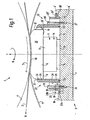
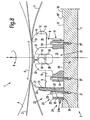
- parts of a press 1 are schematically shown in a side view and cross-section, for instance a wet press or a calender, which is arranged in a machine for the production or treatment of a continuously running web 2 of cellulosic fibrous material, for instance a paper, tissue or board machine, during which production or treatment the fibrous web 2 is, for instance, dewatered by extrusion of water, compressed, surfaced, treated for achieving the correct thickness, etc.
- the press 1 comprises a press device 3 and a counter element 4 arranged opposite to the press device 3, which in the embodiments shown in the figures comprises a rotatably journalled counter roll 4 with the rotation direction R.
- the counter roll 4 is arranged to form a press zone in the form of an extended press nip 5 having a certain width in the machine direction W for pressing the fibrous web 2 during its passage through the press nip 5.
- the press device 3 comprises a press shoe 6, which is arranged substantially across the fibrous web 2, a support element 7, preferably an I-beam, arranged substantially horizontal for supporting the press shoe 6 and at least one power device 8 arranged between the press shoe 6 and the support element 7 for applying a predetermined pressure against the underside 9 of the press shoe 6 in a direction towards the counter element 4 and thereby also against the fibrous web 2 via the press shoe 6.
- the press shoe 6 comprises a concave mating surface 10 facing the counter roll 4, which mating surface 10 is provided with a radius that equals the curvature of the counter roll 4.
- the press device 3 also comprises a flexible and preferably impermeable belt 11 that is arranged to run in a continuous loop around the support element 7 and through the press nip 5 having a sliding contact with the mating surface 10 of the press shoe 6.
- the impermeable web loop 11 may be attached at each side edge to a rotatable roll head for forming a formable press roll having a flexible mantle (not shown) or be arranged to run over a number of rolls, not shown, and through the press nip 5, wherein the fibrous web 2 is pressed between the web loop 11 and a determined part of the surface of the counter roll 4.
- the press shoe 6 comprises a feed conduit 13 for pressurized hydraulic fluid, which is attached along the upstream side 12 of the press shoe 6 and which feed conduit 13 is providing one or more hydrostatic pressure pockets, which are arranged in said mating surface 10 (not shown), via a channel system in the press shoe 6.
- the function of the hydraulic fluid is to form and maintain a friction absorbing layer between the press shoe 6 and the belt 11, which press shoe 6 preferably extends in one piece across the entire belt 11, at the same time as a hydrokinetic pressure is obtained between them.
- the power device 8, which preferably is hydraulically or pneumatically driven, is attached to the support element 7 at its lower end part by means of suitable attachment means, as for instance screws (not shown), and is consequently arranged in a stationary way in relation to said support element 7.
- the press shoe 6 is, within certain determined limits, arranged in a way that is freely movable in all directions in relation to the same power device 8 and at the upper end part of this, see in more detail below.
- the power device 8 comprises a number of press cylinders 14, which are mounted at a certain distance from each other in at least one linear row along the support element 7, and which press cylinders 14 are fixedly connected to the support element 7 but arranged against the underside 9 of the press shoe 6 in said movable way at its upper end parts.
- the press cylinders 14 comprise a combination of several part members, at least comprising one cylinder 15 and one piston 16 and where either the cylinder 15 or the piston 16 may be in two parts, in which the integral part members 15, 16 are arranged in a displaceable way in relation to each other in the press direction, but also somewhat tiltable by means of a gap, hence arranged between said part members 15, 16 and possibly also between the press shoe 6 and the upper part member 15, 16, which is joined to the press shoe 6 in a movable way, for instance by a recess, hence arranged in the press shoe 6.
- the press shoe 6 may rest freely onto each upper piston end (not shown) of a press cylinder 14 for obtaining said free mobility in all directions, which piston end may be somewhat roundish or may comprise a bearing.
- a press cylinder 14 for obtaining a floating support for the press shoe 6 in relation to the support element 7, we refer, for instance, to the documents mentioned above.
- a rectangular assembly area 17 in the form of a shallow, flat recess is milled in the top surface 18 of the support element 7 facing the press shoe 6.
- the assembly area 17, which extends in the longitudinal direction of the support element 7, is limited by two longitudinal and two transverse edges 19, 20, which edges 19, 20 are parallel to each other.
- the power device or the power devices 8 is/are mounted in the way described above.
- a plurality of threaded holes 21, having a determined and common dividing, are milled within said recess 17 and arranged in one or more linear row/s along, and at a certain distance from, the upstream and/or the downstream located longitudinal edge 19', 19.
- a first guide 22 for the press shoe 6 is arranged in a dismountable and adjustable way along the longitudinal edge 19 located downstream.
- Each such downstream guide 22 comprises at least one support 23 and at least one spacing member 24, which supports 23 and spacing members 24 may each be produced in one elongated piece, each preferably in the form of a profiled rail extending along the entire length of the press shoe 6, but they may also consist of a plurality of parts distributed in the cross-direction.
- the support 23 comprises two parts, which consist of a lower assembly part 25 and an upper contact part 26, which latter extends from the lower assembly part 25 in a substantially right angle in relation to the support element 7 and against which contact part 26 the press shoe 6 presses with its downstream facing long side 27.
- the support 23 is arranged in a displaceable way in relation to the support element 7, to the downstream located longitudinal edge 19 and to the power device 8 by means of elongated, parallel grooves 28 milled through the assembly part 25, which grooves 28 extend in the machine direction and in which grooves 28 screws 29 are tightly but releasably screwed in the threaded holes 21 mentioned above.
- the spacing member 24, which is turnable or pivotable, is clamped between the downstream located longitudinal edge 19 and the assembly part 25, which latter also comprises a longitudinal recess 30 for said spacing member 24.
- the spacing member 24 has a cross-section profile, which profile is very precisely sized and comprises several different part members 24a, 24b, etc., having different and predetermined widths a, b, c, d, etc.
- the position of the press shoe 6 in relation to the longitudinal edge 19 located downstream, and thereby also in relation to power devices 8, counter elements 4 and vertical central axis Y of the support element 7, may therefore be varied in a simple, effective and very exact way according to the necessary properties for the present press situation. Since the power device arrangement 8, in the press 1 according to the invention, always is fixedly attached and centered to the vertical central axis Y of the support element 7, the pressure resultant force that occurs during the pressing operation will always have a vertical component part along said central axis Y, regardless of which position the press shoe 6 takes, and which vertical component part then does not give any additional torque.
- the press device 3 also comprises an additional and second guide 32 for the press shoe 6, which is arranged substantially upstream or at least working from the upstream side and substantially in the machine direction against the press shoe 6.
- this second guide 32 constitutes of a similar but reversed guide 32 as the first guide 22 arranged downstream and which second guide 32 also is arranged in the same way as the first guide 22, i.e. in a dismountable and adjustable way, at several predetermined, fixed positions against, and in relation to, the upstream, longitudinal edge 19'.
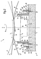
- the second guide 32 for the press shoe 6 comprises two lateral supports 33, which lateral supports 33 are arranged in a dismountable way at the cross ends 35 of the press shoe 6 by means of fasteners 34, threaded holes 21' and elongated, through grooves 28', which extend in a straight line in the machine direction. Furthermore, the lateral supports 33 are steplessly displaceable along each of the two transverse edges 20, 20' between at least two positions, which are predetermined and fixed by the fasteners 34 and the grooves 28'. Each lateral support 33 comprises two parts, which parts consist of a lower assembly part 36 for assembly of the lateral support 33 to the support element 7 and an upper contact part 37.
- This contact part 37 extends from the lower assembly part 36 at a substantially right angle relative to the support element 7 and comprises a preferably vertical contact surface 38 facing downstream.
- the press shoe 6 also comprises a fixed projection 39 at each of its both cross ends 35, against which two projections 39 the contact parts 37 are arranged to abut, each having a contact surface 38 for achieving an upstream guiding of the press shoe 6.
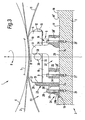
- the second guide 32 for the press shoe 6 comprises two lateral supports 33, which lateral supports 33 are attached in a dismountable way by means of fasteners 34 and threaded holes 21' at the cross ends 35 of the press shoe 6 and also arranged in a turnable way along each of the two transverse edges 20, 20'.
- Each lateral support 33 comprises three parts, which parts consist of a lower assembly part 36 for assembly of the lateral support 33 to the support element 7 and two upper contact parts 37, which are arranged at to two different distances from the lateral support 33 center.
- each of these contact parts 37 extends from the lower assembly part 36 at a substantially right angle relative to the support element 7 and which upper contact parts 37 each comprise a preferably vertical contact surface 38 facing each other.
- the press shoe 6 comprises two fixed projections 39, one at each of its cross ends 35, and against which projections 39 the contact surface 38 of the most upstream located contact part 37 is arranged to abut for an upstream guiding of the press shoe 6.
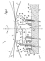
- this press 1 comprises the same component parts, which are arranged in the same way as the third embodiment shown in the figures 5 and 6, except for the difference that the press shoe 6 instead of the fixed projections 39 comprises an eccentric 40 in the form of an eccentrically pivotable projection 39 arranged at each cross end 35 of the press shoe 6.
- a press 1 is shown in a schematic side view comprising a support element 7 in the form of an I-beam.
- the I-beam has a substantially flat waist 41 and the power device arrangement 8 is arranged to function with its resultant force F in alignment with the center plane of the waist 41 in such a way that regardless of the pressure curve set, the press cylinders 14 still work in alignment with the center plane of the waist 41. This because they are arranged in a symmetric and fixed way relative to the waist 41. Thereby may an adjustable pressure profile be obtained while still using an I-beam.
- the guides 22, 32 are thereafter once again tightly screwed, after which the position of the press shoe 6 in figure 1 thus has been moved somewhat downstream compared with figure 2.
- downstream located guide 22 is moved in the same way as described above, while, for the different embodiments of the second guide 32, this is done in the following way.
- each of the lateral supports 33 is loosened so much from the support element 7 that they may be moved in the same direction and as equally much as the downstream located guide 22 has been moved, after which the lateral supports 33 once again are tightened to the support element 7, having a renewed contact against the projection 39 of the press shoe at the new operative position for the press shoe 6.
- each of the lateral supports 33 is entirely loosened from the support element 7, turned a half turn, after which the lateral supports 33 once again are tightened to the support element 7, now having a renewed contact against the projection 39 of the press shoe with the earlier, in relation to the first operative position, inactive contact surface 38 of the contact part 37, which, because of the two different distances of the contact parts 37 from the center of the lateral supports 33, equals the accomplished movement of the press shoe 6 by the first guide 22.
- the first guide 22 is moved in the same way as described above, while the positions of the lateral supports 33 of the second guide 32 are being retained unaltered. Instead, the eccentric 40 at both cross ends 35 of the press shoe 6 is pivoted to a new position, in which new position the eccentrically pivotable projection 39 is in afresh contact with the contact surfaces 38 of the lateral support 33 for guiding and supporting the press shoe 6 at the new, and for the press shoe 6, second operative position.
- the operative positions of the guides 22, 32 may, of course, be more numerous than the two (first and second) operative positions shown in the figures and they may be achieved in a numerous different ways in addition to the ways shown, having spacing members 24, fasteners 29, 34 and eccentrics 40, for instance by means of guide pins, wedges, eccentrically arranged spacing members etc.
- the counter element also may consist of a second press device, preferably a shoe press roll in which the press shoe then is adapted to the press shoe of the first press device so that their sliding surfaces are cooperating in forming a determined press zone there between.
- the actual press shoe is preferably designed in one piece, while the power device or the power devices preferably comprises/comprise several press cylinders having a preferably even distribution along the press shoe.
- one or more, permeable or impermeable clothings may be arranged to run in a loop of its own across a number of guide rolls and through the press nip together with the fibrous web and the belt.
- the said clothings may for instance comprise one or more press felts, which are running trough the nip together with the wet fibrous web while water is being transferred to the press felts when being pressed in the nip.
- the press may consist of a calender or another finishing unit, in which the then substantially entirely dried fibrous web is surfaced and/or shaped, for instance calendered, imprinted etc.
- the press according to the invention may also be used for other webs than paper and cardboard, for instance tissue.
- the power device may then also comprise several, preferably two, mutually parallel rows having several press cylinders in each row across the belt and along the press shoe.
- the press cylinders may also be divided into groups for variation of the pressure across the press shoe.
- the fixed edges in the above-described embodiments, which are formed of the lowered assembly area may, of course, instead consist of edges or other suitable supports mounted on top of the top surface of the support element or projecting from the support element for determining of set baselines from which diverse, nearly exact positions for the press shoe may be set by means of spacing members cooperating in pairs, which together give the selected position for the press shoe.
- the second guide may, in the case it consists of lateral supports, also guide directly or indirectly against the upstream side of the press shoe instead of against the projections mentioned above.
- the second guide instead of the press shoe, may comprise the described projections, and which projections then in turn run in therefore arranged grooves in the press shoe.
- the first and downstream arranged support is moved equally much as the shoe, which then also is the fact for the second guide, which is moved equally much and in the same direction as the first guide.
- movable guides instead of movable guides, different sets of guides, having different geometry (length in the machine direction), may be used. The adjustment may then be done by changing one guide by another.
Landscapes
- Paper (AREA)
- Footwear And Its Accessory, Manufacturing Method And Apparatuses (AREA)
Claims (26)
- Presse für eine Papier-, Zelltuch- oder Kartonmaschine, wobei diese Presse (1) eine Pressvorrichtung (3) und ein Gegenelement (4) aufweist, das gegenüberliegend der Pressvorrichtung (3) angeordnet ist, das angeordnet ist, um in Zusammenarbeit mit der Pressvorrichtung (3) eine Presszone (5) in der Form eines erweiterten Pressspalts auszubilden, der in der Maschinenrichtung (W) eine bestimmte Breite hat, um das Fasergewebe (2) zu pressen, wenn es durch den Pressspalt (5) läuft, wobei die Pressvorrichtung (3) aufweist
einen Pressschuh (6);
ein Stützelement (7) zum Stützen des Pressschuhs (6);
zumindest eine Leistungsvorrichtung (8), die zwischen dem Pressschuh (6) und dem Stützelement (7) angeordnet ist, um gegen den Pressschuh (6) einen Druck in Richtung des Gegenelements (4) anzulegen;
einen flexiblen und vorzugsweise undurchlässigen Gurt (11), der angeordnet ist, um in einer durchgehenden Schleife um das Stützelement (7) und durch den Pressspalt (5) zu laufen, wobei er einen Gleitkontakt mit dem Pressschuh (6) aufweist; und
eine erste Führung (22) für den Pressschuh (6), die stromabwärts des Pressschuhs (6) angeordnet ist und eine Kontaktfläche (31) entgegen dem Pressschuh (6) aufweist;
und wobei die Pressvorrichtung (3) ferner eine zweite Führung (32) für den Pressschuh (6) aufweist, die im Wesentlichen stromaufwärts des Pressschuhs (6) angeordnet ist oder zumindest von der stromaufwärtigen Seite des Pressschuhs (6) aus, und im Wesentlichen in der Maschinenrichtung (W) arbeitet und eine Kontaktfläche (31', 38) aufweist, die angeordnet ist, um ein stromaufwärtiges Führen des Pressschuhs (6) zu erreichen, wobei der Pressschuh (6) in der Maschinenrichtung derart beweglich ist, dass die Position des Pressschuhs (6) in Bezug auf die Leistungsvorrichtung (8) veränderbar ist und dadurch auch das Druckprofil in dem Spalt und die ersten und zweiten Führungen derart einstellbar sind, dass die Kontaktflächen (31, 31', 38) der Führungen (22, 32) in der Maschinenrichtung zusammen mit dem Pressschuh (6) mit einer Bewegung beweglich sind, die gleich der Bewegung des Pressschuhs (6) in der Maschinenrichtung ist. - Presse (1) gemäß Anspruch 1, wobei die erste Führung (22) für den Pressschuh (6) in einer demontierbaren und einstellbaren Art angeordnet ist und zumindest eine Stütze (23) und zumindest ein Abstandsbauteil (24) aufweist.
- Presse (1) gemäß Anspruch 2, wobei jede Stütze (23) und jedes Abstandsbauteil (24) in der Form einer profilierten Schiene hergestellt sind, die sich entlang des Pressschuhs (6) erstreckt.
- Presse (1) gemäß Anspruch 2 oder 3, wobei die Stütze (23) zwei Teile aufweist, die aus einem unteren Bauelement (25) und einem oberen Kontaktteil (26) bestehen, wobei sich der Pressschuh (6) mit diesem Kontaktteil (26) in Kontakt befindet, wobei seine Längsseite (27) stromabwärts zeigt.
- Presse (1) gemäß Anspruch 4, wobei die Stütze (23) in einer versetzbaren Art und Weise bezüglich dem Stützelement (7) und der Leistungsvorrichtung (8) mittels verlängerter, durchgehender Nuten (28) angeordnet ist, die bei dem Bauelement (25) angeordnet sind, wobei sich diese Nuten (28) parallel zueinander in der Maschinenrichtung erstrecken.
- Presse (1) gemäß Anspruch 5, wobei die Stütze (23) mittels Schrauben (29) , die in den Nuten (28) angeordnet sind, fest aber lösbar an das Stützelement (7) geschraubt ist.
- Presse (1) gemäß Anspruch 4, 5 oder 6, wobei das Abstandsbauteil (24) mehrere verschiedene Bauteile (24a, 24b, etc.) mit verschiedenen und vorbestimmten Breiten (a, b, c, d, etc.) aufweist, um eine vorbestimmte und einstellbare Position für das obere Kontaktteil (26) zu dem Pressschuh (6) zu erhalten und um dabei auch die Position des Pressschuhs (6) bezüglich der integrierten Leistungsvorrichtungen (8) zu variieren.
- Presse (1) gemäß einem der vorangehenden Ansprüche, wobei die zweite Führung (32) für den Pressschuh (6) zwei laterale Stützen (33) aufweist, die in einer demontierbaren und versetzbaren Art an den Querenden (35) des Pressschuhs (6) angeordnet sind.
- Presse (1) gemäß Anspruch 8, wobei die lateralen Stützen (33) mittels Befestigungselementen (34) und verlängerten, durchgehenden Nuten (28'), die sich sukzessive in einer geraden Linie in der Maschinenrichtung zwischen zumindest zwei Positionen erstrecken, die durch die Befestigungselemente (34) und die Nuten (28') vorbestimmt und festgesetzt werden, in einer stufenlos variierbaren Art versetzbar sind.
- Presse (1) gemäß einem der Ansprüche 1 oder 9, wobei jede laterale Stütze (33) ein unteres Bauelement (36) zum Befestigen der lateralen Stütze (33) an dem Stützelement (7) und ein oberes Kontaktteil (37) aufweist, das eine vorzugsweise vertikale Kontaktfläche (38) für ein stromaufwärtiges Führen des Pressschuhs (6) hat, die stromabwärts zeigt.
- Presse (1) gemäß Anspruch 10, wobei der Pressschuh (6) einen feststehenden Vorsprung (39) an jedem seiner zwei Querenden (35) aufweist, und wobei gegen diese zwei Vorsprünge (39) die Kontaktteile (37) angeordnet sind, um in Kontakt zu sein, wobei jedes selbst eine Kontaktfläche (38) hat.
- Presse (1) gemäß einem der Ansprüche 1 bis 7, wobei die zweite Führung (32) für den Pressschuh (6) zwei laterale Stützen (33) aufweist, wobei diese lateralen Stützen (33) an den Querenden (35) des Pressschuhs (6) mittels Befestigungselementen (34) in einer demontierbaren und drehbaren Art befestigt sind.
- Presse (1) gemäß Anspruch 12, wobei jede laterale Stütze (33) ein unteres Bauelement (36) zum Montieren der lateralen Stütze (33) an das Stützelement (7) und zwei obere Kontaktteile (37) aufweist, die an verschiedenen Abständen von der Mitte der lateralen Stütze (33) angeordnet sind.
- Presse (1) gemäß Anspruch 13, wobei die oberen Kontaktteile (37) jeweils eine vorzugsweise vertikale Kontaktfläche aufweisen, die der anderen Kontaktfläche (38) zugewandt ist.
- Presse (1) gemäß Anspruch 14, wobei der Pressschuh (6) zwei befestigte Vorsprünge (39), einen an jedem seiner Querenden (35), aufweist, und wobei gegen diese Vorsprünge (39) die Kontaktfläche (38) des am meisten stromaufwärtig positionierten Kontaktteils (37) angeordnet ist, um für ein stromaufwärtiges Führen des Pressschuhs (6) anzugrenzen.
- Presse (1) gemäß einem der vorangehenden Ansprüche, wobei der Pressschuh (6) einen Exzenter (40) in der Form eines exzentrisch drehbaren Vorsprungs (39) aufweist, der an jedem Querende (35) des Pressschuhs (6) angeordnet ist.
- Presse (1) gemäß einem der vorangehenden Ansprüche in Kombination mit Anspruch 2, wobei das Abstandsbauteil (24, 24') in einer wend- oder drehbaren Art angeordnet ist.
- Presse (1) gemäß einem der vorangehenden Ansprüche, wobei die Leistungsvorrichtungen (8) eine Anzahl von Presszylindern (14) aufweisen, die entlang dem Pressschuh (6) in einer geraden Linie und bei einem bestimmten Abstand voneinander angeordnet sind.
- Presse (1) gemäß Anspruch 18, wobei der Pressschuh (6) auf den oberen Kolbenenden (15) des Presszylinders (14) freibleibend angeordnet ist, um die freie Beweglichkeit in alle Richtungen zu erhalten.
- Presse (1) gemäß einem der vorangehenden Ansprüche, wobei die zweite Führung (32) aus einer ähnlichen, jedoch umgedrehten Führung (32) als die erste Führung (22) besteht, die stromabwärts angeordnet ist, und wobei die zweite Führung (32) in einer demontierbaren und einstellbaren Art bei mehreren vorbestimmten und feststehenden Positionen entgegen und in Bezug auf die erste Führung (22) angeordnet ist.
- Presse (1) gemäß einem der vorangehenden Ansprüche, wobei die Pressvorrichtung (3) quer zu der Maschinenrichtung (W) gerichtet ist.
- Presse (1) gemäß einem der vorangehenden Ansprüche, wobei das Gegenelement (4) eine drehbar gelagerte Gegenwalze (4) aufweist, die im Wesentlichen parallel zu der Pressvorrichtung (3) liegt.
- Presse (1) gemäß einem der vorangehenden Ansprüche, wobei das Stützelement (7) zum Stützen des Pressschuhs (6) aus einem I-Träger besteht, der ein im Wesentlichen flaches Mittelteil (41) hat.
- Presse (1) gemäß Anspruch 23, wobei die resultierende Kraft F der Leistungsvorrichtungsanordnung (8) angeordnet ist, um in Ausrichtung mit der mittleren Ebene des Mittelteils (41) zu arbeiten.
- Presse (1) gemäß einem der vorangehenden Ansprüche, wobei sich der Pressschuh (6) in einem einzigen Stück über den gesamten Gurt (11) erstreckt und wobei eine reibungsabsorbierende Schicht eines Hydraulikfluids mit einem bestimmten hydrokinetischen Druck zwischen dem Pressschuh (6) und dem Gurt (11) angeordnet ist.
- Verfahren zum Abändern des Druckprofils bei einer Presse (1) für eine Papier-, Zelltuch- oder Kartonmaschine, wobei die Presse (1) eine Pressvorrichtung (3) und ein Gegenelement (4) aufweist, das gegenüberliegend der Pressvorrichtung (3) angeordnet ist, das in Zusammenarbeit mit der Pressvorrichtung (3) eine Presszone (5) in der Form eines verlängerten Pressspalts (5) mit einer bestimmten Breite in der Maschinenrichtung (W) ausbildet, so dass ein Pressen des Fasergewebes (2) während des Durchlaufens durch den Pressspalte (5) auftritt, wobei die Pressvorrichtung (3) aufweist
einen Pressschuh (6);
ein Stützelement (7), das den Pressschuh (6) stützt;
zumindest eine Leistungsvorrichtung (8), die zwischen dem Pressschuh (6) und dem Stützelement (7) zum Anlegen eines Drucks gegen den Pressschuh (6) in Richtung dem Gegenelement (4) ;
einen flexiblen und vorzugsweise undurchlässigen Gurt (11), der in einer durchgehenden Schleife um das Stützelement (7) und durch den Pressspalt (5) läuft, der einen Gleitkontakt mit dem Pressschuh (6) hat;
eine erste Führung (22) für den Pressschuh (6), die stromabwärts des Pressschuhs (6) angeordnet ist und eine Kontaktfläche (31) gegen den Pressschuh (6) hat;
eine zweite Führung (32) für den Pressschuh (6), die im Wesentlichen stromaufwärts des Pressschuhs (6) oder zumindest auf der stromaufwärtigen Seite des Pressschuhs (6) angeordnet ist und im Wesentlichen in der Maschinenrichtung (W) wirkt und eine Kontaktfläche (31', 38) hat, die angeordnet ist, um ein stromaufwärtiges Führen des Pressschuhs (6) zu erreichen;
und wobei der Pressschuh (6) in der Maschinenrichtung derart bewegt wird, dass die Position des Pressschuhs (6) in Bezug auf die Leistungsvorrichtung (8) geändert wird und dabei auch das Druckprofil in dem Spalt geändert wird und die ersten und zweiten Führungen derart eingestellt werden, dass die Kontaktflächen (31, 31', 38) der Führungen (22, 32) zusammen mit dem Pressschuh (6) in der Maschinenrichtung in einer Bewegung bewegt werden, die gleich der Bewegung des Pressschuhs (6) in der Maschinenrichtung ist.
Applications Claiming Priority (3)
| Application Number | Priority Date | Filing Date | Title |
|---|---|---|---|
| SE0002010A SE516410C2 (sv) | 2000-05-29 | 2000-05-29 | Press i en maskin för framställning av en kontinuerligt löpande bana av cellulosahaltigt fibermaterial och förfarande för att förändra tryckprofilen i en sådan press |
| SE0002010 | 2000-05-29 | ||
| PCT/SE2001/000731 WO2001092636A1 (en) | 2000-05-29 | 2001-04-04 | Shoe press |
Publications (2)
| Publication Number | Publication Date |
|---|---|
| EP1285121A1 EP1285121A1 (de) | 2003-02-26 |
| EP1285121B1 true EP1285121B1 (de) | 2007-01-17 |
Family
ID=20279889
Family Applications (1)
| Application Number | Title | Priority Date | Filing Date |
|---|---|---|---|
| EP01918128A Expired - Lifetime EP1285121B1 (de) | 2000-05-29 | 2001-04-04 | Schuhpresse |
Country Status (8)
| Country | Link |
|---|---|
| EP (1) | EP1285121B1 (de) |
| JP (1) | JP4879445B2 (de) |
| CN (1) | CN1192144C (de) |
| AT (1) | ATE351938T1 (de) |
| AU (1) | AU2001244994A1 (de) |
| DE (1) | DE60126079T2 (de) |
| SE (1) | SE516410C2 (de) |
| WO (1) | WO2001092636A1 (de) |
Families Citing this family (5)
| Publication number | Priority date | Publication date | Assignee | Title |
|---|---|---|---|---|
| DE10351294A1 (de) * | 2003-10-31 | 2005-06-02 | Voith Paper Patent Gmbh | Anpresseinrichtung |
| FI125825B (fi) | 2014-10-24 | 2016-02-29 | Valmet Technologies Inc | Kuiturainakoneen hihnatela |
| DE102019104389A1 (de) * | 2019-02-21 | 2020-08-27 | Voith Patent Gmbh | Schuhpresse |
| DE102019119905A1 (de) * | 2019-07-23 | 2021-01-28 | Voith Patent Gmbh | Schuhpresse |
| CN116808655A (zh) * | 2023-08-28 | 2023-09-29 | 南京通钰环保科技有限公司 | 一种布料自动进出和出渣洗布的立式压榨机 |
Family Cites Families (5)
| Publication number | Priority date | Publication date | Assignee | Title |
|---|---|---|---|---|
| FI65103C (fi) * | 1982-05-05 | 1984-03-12 | Tampella Oy Ab | Laongzonspress foer en pappersmaskin |
| SE461154B (sv) * | 1988-05-25 | 1990-01-15 | Valmet Paper Machinery Inc | Press med laangt nyp foer pappers- eller kartongmaskiner |
| DE4409316C1 (de) * | 1994-03-18 | 1995-06-29 | Escher Wyss Gmbh | Langspaltpressvorrichtung zur Behandlung einer Faserstoffbahn |
| DE19622020A1 (de) * | 1996-05-31 | 1997-12-04 | Voith Sulzer Papiermasch Gmbh | Preßwalze |
| CA2259768C (en) * | 1998-01-30 | 2004-05-11 | Valmet Corporation | Shoe press |
-
2000
- 2000-05-29 SE SE0002010A patent/SE516410C2/sv not_active IP Right Cessation
-
2001
- 2001-04-04 WO PCT/SE2001/000731 patent/WO2001092636A1/en not_active Ceased
- 2001-04-04 AU AU2001244994A patent/AU2001244994A1/en not_active Abandoned
- 2001-04-04 EP EP01918128A patent/EP1285121B1/de not_active Expired - Lifetime
- 2001-04-04 JP JP2002500025A patent/JP4879445B2/ja not_active Expired - Fee Related
- 2001-04-04 CN CNB018102859A patent/CN1192144C/zh not_active Expired - Fee Related
- 2001-04-04 DE DE60126079T patent/DE60126079T2/de not_active Expired - Lifetime
- 2001-04-04 AT AT01918128T patent/ATE351938T1/de not_active IP Right Cessation
Also Published As
| Publication number | Publication date |
|---|---|
| CN1441869A (zh) | 2003-09-10 |
| EP1285121A1 (de) | 2003-02-26 |
| JP2003535232A (ja) | 2003-11-25 |
| CN1192144C (zh) | 2005-03-09 |
| AU2001244994A1 (en) | 2001-12-11 |
| DE60126079T2 (de) | 2007-07-12 |
| WO2001092636A1 (en) | 2001-12-06 |
| SE0002010L (sv) | 2001-11-30 |
| SE0002010D0 (sv) | 2000-05-29 |
| ATE351938T1 (de) | 2007-02-15 |
| JP4879445B2 (ja) | 2012-02-22 |
| SE516410C2 (sv) | 2002-01-15 |
| DE60126079D1 (de) | 2007-03-08 |
Similar Documents
| Publication | Publication Date | Title |
|---|---|---|
| CA1322122C (en) | Press with extended nip | |
| EP0487483B1 (de) | Verfahren und Vorrichtung zur Entwässerung einer Papierbahn durch Pressen | |
| US5262010A (en) | Dewatering device with adjustable force elements for the web-forming section of a papermaking machine | |
| CA1318806C (en) | Press with extended nip | |
| EP0298057A2 (de) | Verfahren und Vorrichtung zum Steuern einer Zonenwalze | |
| US4865692A (en) | Stationary support member for web producing machine | |
| CA2067986C (en) | Wire loading device in a paper machine | |
| CA2081960A1 (en) | Wide nip web press and method using a press shoe with two pivots | |
| US5501145A (en) | Multi-purpose calendar | |
| CA2538046C (en) | Support body, holding device therefor, apparatus with said body for treatment of a web, methods of forming an extended nip in the apparatus and controlling load in the nip | |
| EP1285121B1 (de) | Schuhpresse | |
| US4885088A (en) | Filter belt press | |
| EP1127187B1 (de) | Presse zur entwässerung einer faserbahn | |
| FI107134B (fi) | Jatkuvatoiminen puristin | |
| JPH0770970A (ja) | プレス部分の作動方法および製紙機械のプレス装置 | |
| US6517683B2 (en) | Shoe press with movable guides to alter machine direction shoe position | |
| JP4316709B2 (ja) | プレス装置 | |
| CA2110886C (en) | Method and device for controlling a wire in a forming gap of a web former | |
| US20060144545A1 (en) | Press device having an extended press nip for pressing of a travelling paperboard web, and procedure for controlling the pressure curve in the machine direction by such press nip | |
| CA2294389C (en) | Device for dewatering solid/liquid suspensions, especially pulp suspensions | |
| CA2260508A1 (en) | Method for operating a calender roll system, and calender roll system | |
| EP1240387B1 (de) | Verfahren und vorrichtung zum pressen einer papierbahn | |
| US6319363B1 (en) | Sheet forming system and method for controlling the same | |
| FI90263B (fi) | Pitkävyöhykepuristin |
Legal Events
| Date | Code | Title | Description |
|---|---|---|---|
| PUAI | Public reference made under article 153(3) epc to a published international application that has entered the european phase |
Free format text: ORIGINAL CODE: 0009012 |
|
| 17P | Request for examination filed |
Effective date: 20021102 |
|
| AK | Designated contracting states |
Kind code of ref document: A1 Designated state(s): AT BE CH CY DE DK ES FI FR GB GR IE IT LI LU MC NL PT SE TR |
|
| AX | Request for extension of the european patent |
Extension state: AL LT LV MK RO SI |
|
| RIN1 | Information on inventor provided before grant (corrected) |
Inventor name: BROX, ERIK |
|
| RAP1 | Party data changed (applicant data changed or rights of an application transferred) |
Owner name: METSO PAPER, INC. |
|
| RAP1 | Party data changed (applicant data changed or rights of an application transferred) |
Owner name: METSO PAPER, INC. |
|
| GRAP | Despatch of communication of intention to grant a patent |
Free format text: ORIGINAL CODE: EPIDOSNIGR1 |
|
| GRAS | Grant fee paid |
Free format text: ORIGINAL CODE: EPIDOSNIGR3 |
|
| GRAA | (expected) grant |
Free format text: ORIGINAL CODE: 0009210 |
|
| AK | Designated contracting states |
Kind code of ref document: B1 Designated state(s): AT BE CH CY DE DK ES FI FR GB GR IE IT LI LU MC NL PT SE TR |
|
| PG25 | Lapsed in a contracting state [announced via postgrant information from national office to epo] |
Ref country code: AT Free format text: LAPSE BECAUSE OF FAILURE TO SUBMIT A TRANSLATION OF THE DESCRIPTION OR TO PAY THE FEE WITHIN THE PRESCRIBED TIME-LIMIT Effective date: 20070117 Ref country code: LI Free format text: LAPSE BECAUSE OF FAILURE TO SUBMIT A TRANSLATION OF THE DESCRIPTION OR TO PAY THE FEE WITHIN THE PRESCRIBED TIME-LIMIT Effective date: 20070117 Ref country code: NL Free format text: LAPSE BECAUSE OF FAILURE TO SUBMIT A TRANSLATION OF THE DESCRIPTION OR TO PAY THE FEE WITHIN THE PRESCRIBED TIME-LIMIT Effective date: 20070117 Ref country code: DK Free format text: LAPSE BECAUSE OF FAILURE TO SUBMIT A TRANSLATION OF THE DESCRIPTION OR TO PAY THE FEE WITHIN THE PRESCRIBED TIME-LIMIT Effective date: 20070117 Ref country code: CH Free format text: LAPSE BECAUSE OF FAILURE TO SUBMIT A TRANSLATION OF THE DESCRIPTION OR TO PAY THE FEE WITHIN THE PRESCRIBED TIME-LIMIT Effective date: 20070117 |
|
| REG | Reference to a national code |
Ref country code: GB Ref legal event code: FG4D |
|
| REG | Reference to a national code |
Ref country code: CH Ref legal event code: EP |
|
| REG | Reference to a national code |
Ref country code: IE Ref legal event code: FG4D |
|
| REF | Corresponds to: |
Ref document number: 60126079 Country of ref document: DE Date of ref document: 20070308 Kind code of ref document: P |
|
| PG25 | Lapsed in a contracting state [announced via postgrant information from national office to epo] |
Ref country code: SE Free format text: LAPSE BECAUSE OF FAILURE TO SUBMIT A TRANSLATION OF THE DESCRIPTION OR TO PAY THE FEE WITHIN THE PRESCRIBED TIME-LIMIT Effective date: 20070417 |
|
| PG25 | Lapsed in a contracting state [announced via postgrant information from national office to epo] |
Ref country code: ES Free format text: LAPSE BECAUSE OF FAILURE TO SUBMIT A TRANSLATION OF THE DESCRIPTION OR TO PAY THE FEE WITHIN THE PRESCRIBED TIME-LIMIT Effective date: 20070428 |
|
| PG25 | Lapsed in a contracting state [announced via postgrant information from national office to epo] |
Ref country code: PT Free format text: LAPSE BECAUSE OF FAILURE TO SUBMIT A TRANSLATION OF THE DESCRIPTION OR TO PAY THE FEE WITHIN THE PRESCRIBED TIME-LIMIT Effective date: 20070618 |
|
| NLV1 | Nl: lapsed or annulled due to failure to fulfill the requirements of art. 29p and 29m of the patents act | ||
| REG | Reference to a national code |
Ref country code: CH Ref legal event code: PL |
|
| PLBE | No opposition filed within time limit |
Free format text: ORIGINAL CODE: 0009261 |
|
| STAA | Information on the status of an ep patent application or granted ep patent |
Free format text: STATUS: NO OPPOSITION FILED WITHIN TIME LIMIT |
|
| 26N | No opposition filed |
Effective date: 20071018 |
|
| GBPC | Gb: european patent ceased through non-payment of renewal fee |
Effective date: 20070417 |
|
| PG25 | Lapsed in a contracting state [announced via postgrant information from national office to epo] |
Ref country code: BE Free format text: LAPSE BECAUSE OF FAILURE TO SUBMIT A TRANSLATION OF THE DESCRIPTION OR TO PAY THE FEE WITHIN THE PRESCRIBED TIME-LIMIT Effective date: 20070117 |
|
| PG25 | Lapsed in a contracting state [announced via postgrant information from national office to epo] |
Ref country code: GB Free format text: LAPSE BECAUSE OF NON-PAYMENT OF DUE FEES Effective date: 20070417 Ref country code: FR Free format text: LAPSE BECAUSE OF FAILURE TO SUBMIT A TRANSLATION OF THE DESCRIPTION OR TO PAY THE FEE WITHIN THE PRESCRIBED TIME-LIMIT Effective date: 20070907 Ref country code: IT Free format text: LAPSE BECAUSE OF FAILURE TO SUBMIT A TRANSLATION OF THE DESCRIPTION OR TO PAY THE FEE WITHIN THE PRESCRIBED TIME-LIMIT Effective date: 20070117 Ref country code: GR Free format text: LAPSE BECAUSE OF FAILURE TO SUBMIT A TRANSLATION OF THE DESCRIPTION OR TO PAY THE FEE WITHIN THE PRESCRIBED TIME-LIMIT Effective date: 20070418 |
|
| PG25 | Lapsed in a contracting state [announced via postgrant information from national office to epo] |
Ref country code: IE Free format text: LAPSE BECAUSE OF NON-PAYMENT OF DUE FEES Effective date: 20070404 |
|
| PG25 | Lapsed in a contracting state [announced via postgrant information from national office to epo] |
Ref country code: FR Free format text: LAPSE BECAUSE OF FAILURE TO SUBMIT A TRANSLATION OF THE DESCRIPTION OR TO PAY THE FEE WITHIN THE PRESCRIBED TIME-LIMIT Effective date: 20070117 |
|
| PG25 | Lapsed in a contracting state [announced via postgrant information from national office to epo] |
Ref country code: MC Free format text: LAPSE BECAUSE OF NON-PAYMENT OF DUE FEES Effective date: 20070430 |
|
| PG25 | Lapsed in a contracting state [announced via postgrant information from national office to epo] |
Ref country code: CY Free format text: LAPSE BECAUSE OF FAILURE TO SUBMIT A TRANSLATION OF THE DESCRIPTION OR TO PAY THE FEE WITHIN THE PRESCRIBED TIME-LIMIT Effective date: 20070117 |
|
| PG25 | Lapsed in a contracting state [announced via postgrant information from national office to epo] |
Ref country code: LU Free format text: LAPSE BECAUSE OF NON-PAYMENT OF DUE FEES Effective date: 20070404 |
|
| PG25 | Lapsed in a contracting state [announced via postgrant information from national office to epo] |
Ref country code: TR Free format text: LAPSE BECAUSE OF FAILURE TO SUBMIT A TRANSLATION OF THE DESCRIPTION OR TO PAY THE FEE WITHIN THE PRESCRIBED TIME-LIMIT Effective date: 20070117 |
|
| PGFP | Annual fee paid to national office [announced via postgrant information from national office to epo] |
Ref country code: FI Payment date: 20140411 Year of fee payment: 14 |
|
| PGFP | Annual fee paid to national office [announced via postgrant information from national office to epo] |
Ref country code: DE Payment date: 20150421 Year of fee payment: 15 |
|
| PG25 | Lapsed in a contracting state [announced via postgrant information from national office to epo] |
Ref country code: FI Free format text: LAPSE BECAUSE OF NON-PAYMENT OF DUE FEES Effective date: 20150404 |
|
| REG | Reference to a national code |
Ref country code: DE Ref legal event code: R119 Ref document number: 60126079 Country of ref document: DE |
|
| PG25 | Lapsed in a contracting state [announced via postgrant information from national office to epo] |
Ref country code: DE Free format text: LAPSE BECAUSE OF NON-PAYMENT OF DUE FEES Effective date: 20161101 |