EP1285225B1 - Vorrichtung zur inspektion der schienen einer bahn- oder strassenbahnlinie - Google Patents
Vorrichtung zur inspektion der schienen einer bahn- oder strassenbahnlinie Download PDFInfo
- Publication number
- EP1285225B1 EP1285225B1 EP01936788A EP01936788A EP1285225B1 EP 1285225 B1 EP1285225 B1 EP 1285225B1 EP 01936788 A EP01936788 A EP 01936788A EP 01936788 A EP01936788 A EP 01936788A EP 1285225 B1 EP1285225 B1 EP 1285225B1
- Authority
- EP
- European Patent Office
- Prior art keywords
- rail
- railway
- laser
- measurement
- unit
- Prior art date
- Legal status (The legal status is an assumption and is not a legal conclusion. Google has not performed a legal analysis and makes no representation as to the accuracy of the status listed.)
- Expired - Lifetime
Links
- 238000012544 monitoring process Methods 0.000 title claims abstract description 5
- 238000005259 measurement Methods 0.000 claims abstract description 38
- 230000005489 elastic deformation Effects 0.000 claims description 4
- 239000011521 glass Substances 0.000 claims description 2
- 238000011144 upstream manufacturing Methods 0.000 claims 1
- 230000000694 effects Effects 0.000 description 3
- 238000000034 method Methods 0.000 description 2
- 230000003287 optical effect Effects 0.000 description 2
- 230000010355 oscillation Effects 0.000 description 2
- 230000002159 abnormal effect Effects 0.000 description 1
- 238000004140 cleaning Methods 0.000 description 1
- 239000011159 matrix material Substances 0.000 description 1
- 238000000691 measurement method Methods 0.000 description 1
- 239000002184 metal Substances 0.000 description 1
- 230000000737 periodic effect Effects 0.000 description 1
- 238000005096 rolling process Methods 0.000 description 1
- 239000007787 solid Substances 0.000 description 1
Images

Classifications
-
- B—PERFORMING OPERATIONS; TRANSPORTING
- B61—RAILWAYS
- B61L—GUIDING RAILWAY TRAFFIC; ENSURING THE SAFETY OF RAILWAY TRAFFIC
- B61L23/00—Control, warning or like safety means along the route or between vehicles or trains
- B61L23/04—Control, warning or like safety means along the route or between vehicles or trains for monitoring the mechanical state of the route
- B61L23/042—Track changes detection
- B61L23/045—Rail wear
-
- B—PERFORMING OPERATIONS; TRANSPORTING
- B61—RAILWAYS
- B61K—AUXILIARY EQUIPMENT SPECIALLY ADAPTED FOR RAILWAYS, NOT OTHERWISE PROVIDED FOR
- B61K9/00—Railway vehicle profile gauges; Detecting or indicating overheating of components; Apparatus on locomotives or cars to indicate bad track sections; General design of track recording vehicles
- B61K9/08—Measuring installations for surveying permanent way
-
- G—PHYSICS
- G01—MEASURING; TESTING
- G01B—MEASURING LENGTH, THICKNESS OR SIMILAR LINEAR DIMENSIONS; MEASURING ANGLES; MEASURING AREAS; MEASURING IRREGULARITIES OF SURFACES OR CONTOURS
- G01B11/00—Measuring arrangements characterised by the use of optical techniques
- G01B11/24—Measuring arrangements characterised by the use of optical techniques for measuring contours or curvatures
- G01B11/245—Measuring arrangements characterised by the use of optical techniques for measuring contours or curvatures using a plurality of fixed, simultaneously operating transducers
Definitions
- This invention relates to an apparatus for monitoring the rails of a railway or tramway line.
- the rails of a railway or tramway line are known to undergo wear and deformation with use, these tending to increase with time until they affect the entire rolling stock with vibration, noise and abnormal stressing, which progressively increase until the rails have to be ground or replaced.
- the correct moment at which such work needs to be carried out depends on the extent of the deformation, which can be evaluated by periodic measurements of the rail parameters, using particular contact sensors which however are able to operate only on individual parameters and substantially limit the usability of the measured data.
- a general laser measurement method known as triangulation can be used to measure the profile of objects in general without contact.
- the object is struck with a laser light beam, a video camera being used, with its optical axis inclined to the direction of the laser beam, to read the shape generated by the interference between this beam and the object under examination.
- This method has found many applications in various technical sectors, but has never been applied to the railway or tramway sector to measure the profile of a rail while in movement, and in reality it would seem to be inapplicable, given the specific requirements of this sector and in particular the need to make the measurement while in movement at high speed, the need to measure all the parameters necessary for complete knowledge of the state of the railway or tramway line, and basically the need to handle all its data with a single information technology system to enable an analysis of the correlation between the various data to be achieved.
- DE-A-19510560 discloses a monitor having at least one light source emitting a narrow beam to illuminate the contours of the rails to be inspected and at least one camera continuosly recording and storing image data from the light beam reflected from the rail.
- the beam lies in a plane at a defined angle to the vertical piano of the rail but the light source is displaced or located sideways and upwards relative to the horizontal contact plans at top of rail surface over an area.
- the light source and the camera are mounted on a measurement head and the camera is located at a defined angle relative to the vertical plane of the rail and the horizontal contact plane.
- An object of the invention is to measure the undulatory wear of the rails.
- a further object of the invention is to measure all the parameters of a railway or tramway line without any contact with the rails and without having to use mechanical centering devices.
- a particular object of the invention is to acquire information concerning the real profile of the rail, its degree of wear and its vertical and transverse deformation.
- Another object of the invention is to be also able to effect these measurements at the points end of a rail.
- Another object of the invention is to measure the geometry parameters of the rails, including their difference in height
- Another object of the invention is to effect all the rail measurements with the measurement apparatus insensitive to oscillation and deformation of the vehicle on which it is mounted.
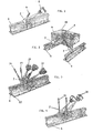
- the apparatus of the invention uses the principle of measurement based on optical triangulation obtained with a laser beam and a dot matrix. More specifically, with reference to Figures 1 2 and 3 which schematically illustrate the principle on which the measurements of the profile of the rail is based according to the prior art, the laser beam 2 is generated by a solid state source 4, for example by a cylindrical lens (not shown) able to uniformly distribute the beam 2 and shape it as a lamina.
- a solid state source 4 for example by a cylindrical lens (not shown) able to uniformly distribute the beam 2 and shape it as a lamina.
- the Interference between the laminar laser beam 2 and the rail 6 displays a line of light related to the rail profile, this latter being read by a special video camera 8 positioned at a certain angle to the laser beam 2 and using a high resolution sensor (1000 x 1000 pixel) and very high acquisition frequency (100-2000 determinations/second).
- the digital signal generated by said video camera 8 and corresponding to the line of interference of the laser beam 2 with the rail 6 is fed to a processor unit which, on the basis of the geometrical parameters of the apparatus, is able to reconstruct the real profile of the rail with high precision.
- the apparatus comprises two triangulation reading devices, one for each rail 6, which together form a measurement unit 10 mounted on board a railway carriage, on which the processor unit is also installed.
- the carnage can be equipped with a recording unit able to memorize the output signals of the two reading devices for their subsequent processing.
- the two triangulation reading devices of the described measurement unit 10 are positioned such that the two laser beams 2 emitted by the two sources 4 are focused on the inner side of the two rails 6 and hence display their inner upper bands, i.e. those most significant in determining any deformation and/or wear.
- each rail 6 there is associated a measurement unit comprising three triangulation reading devices, i.e. three laser sources 14 and three video cameras 18, operating on three different longitudinal bands (inner, upper, outer) of each rail 6, to measure at a predetermined frequency the complete profile of each rail.
- three triangulation reading devices i.e. three laser sources 14 and three video cameras 18, operating on three different longitudinal bands (inner, upper, outer) of each rail 6, to measure at a predetermined frequency the complete profile of each rail.
- the real profile of the rail is hence transmitted to the processor unit, which compares it with the theoretical profile to determine the degree of wear of the rail.
- each measurement unit comprises a further pair of triangulation reading devices positioned longitudinally aligned along each rail 6 and focused on the top of the rail head.
- the two video cameras 28 read the top of the rail profile, to enable the processor unit to analyze the succession of profile parts read with the predetermined frequency and to determine whether the rail contact surface is rectilinear.
- the railway or tramway carriage there are installed for each rail 6 three reading devices 18 for the transverse profile of the rail, which act on three different longitudinal bands of the rail, and two longitudinally aligned reading devices 28 focused on the top of the rail head and forming with the preceding three a central measurement unit 10.
- a further two end measurement units namely a front 20 and a rear 30, preferably positioned at the maximum distance from the central unit 10 compatible with the longitudinal dimensions of the carriage.
- the front end unit 20 and the rear end unit 30 each comprises, for each rail 6, a triangulation reading device, which with the corresponding reading device of the central unit 10 is able, with the predetermined frequency, to read at three longitudinally spaced-apart points of each rail the two characteristic coordinates of the point at that instant, i.e. the vertical coordinate, measured on the top of the horizontal surface of the rail, and the horizontal coordinate, measured on the inner vertical wall of the rail head.
- These two coordinates, which as stated are read at three longitudinally spaced-apart points enable the processor unit to calculate the various parameters of the track geometry, and in particular:
- Figure 6 shows schematically the principle of compensation for the errors due to elastic deformation of the railway or tramway carriage.
- the position in height of each triangulation reading device located in the two end measurement units 20 and 30 is monitored by a laser bar 32 emitted by a source 34 positioned in the central measurement unit 10 and received by a sensor 16 positioned in the end measurement unit 20, 30 and able to constitute a precise alignment of the points of measurement. Lack of alignment results in a signal which by means of suitable software is able to automatically compensate the resultant measurement errors.
- Each central measurement unit 10 and end measurement unit 20, 30 is preferably contained in a strong metal container (see Figure 7) provided with brackets for its mounting on the frame of the carriage.
- the bottom of the container 22, facing the rails 6, is provided with windows 36 for the laser sources 24 and for the video cameras 18, 28 the windows being able to be simultaneously closed by a slidable protection screen 26, operated automatically by the system.
Landscapes
- Engineering & Computer Science (AREA)
- Mechanical Engineering (AREA)
- Physics & Mathematics (AREA)
- General Physics & Mathematics (AREA)
- Length Measuring Devices By Optical Means (AREA)
- Train Traffic Observation, Control, And Security (AREA)
- Management, Administration, Business Operations System, And Electronic Commerce (AREA)
- Lasers (AREA)
- Replacing, Conveying, And Pick-Finding For Filamentary Materials (AREA)
- Length Measuring Devices With Unspecified Measuring Means (AREA)
Claims (7)
- Laservorrichtung zur Inspektion der Schienen einer Eisenbahn- oder Straßenbahnlinie, welche eine Messeinheit (6) für jede Schiene umfasst, die mit Triangulierungslesevorrichtungen versehen ist, wobei jede der Triangulierungslesevorrichtungen eine Laserquelle (24), welche so eingerichtet ist, dass Sie einen linearen Laserstrahl (2) erzeugt und den besagten Strahl auf die zu untersuchende Schiene (6) richtet, und eine Videokamera (28) umfasst, welche in einem Winkel zu dem Laserstrahl angeordnet ist, wobei die Laservorrichtung eine Prozessoreinheit zum Verarbeiten des Signals umfasst, welches durch die besagten Messeinheiten übertragen wird, wobei die besagten Messeinheiten und die besagte Prozessoreinheit an einem Eisenbahn- oder Straßenbahnwagon befestigt sind, welcher so ausgebildet ist, dass er sich entlang der besagten Eisenbahn- oder Straßenbahnlinie fortbewegt, dadurch gekennzeichnet, dass:die besagte Messeinheit mindestens zwei Triangulierungslesevorrichtungen umfasst, welche entlang der Achse der entsprechenden Schiene (6) ausgerichtet und auf den oberen Teil des Schienenkopfes fokussiert sind, unddie besagte Prozessoreinheit Sofwaremittel umfasst, welche so ausgebildet sind, dass sie den Differenzialquotienten der Differenzialmessung errechnen, welche von jedem der mindestens zwei besagten Triangulierungslesevorrichtungen erhalten werden, um so die wellenförmige Abnutzung der Schienen festzustellen.
- Laservorrichtung nach Anspruch 1, dadurch gekennzeichnet, dass jede Messeinheit außerdem eine Profillesegerät umfasst, welches aus mindestens einer Triangulierungslesevorrichtung, welche mindestens an dem Innenteil der entsprechenden Schiene arbeitet, besteht.
- Laservorrichtung nach Anspruch 2, dadurch gekennzeichnet, dass sie eine Messeinheit (10), in welcher die besagten Triangulierungslesevorrichtungen angeordnet sind und ein Paar von Endmesseinheiten (20, 30) umfasst, welche stromauf- und stromabwärts der besagten zentralen Messeinheit (10) angebracht sind und die jeweils mindestens eine Profilleseeinheit des gleichen Typs wie in der besagten zentralen Einheit (10) umfassen, um zusammen mit der Letzteren die Spurengeometrie durch das Verarbeiten der Signale, die von den besagten Profillesegerät erzeugt werden, festzustellen.
- Vorrichtung nach Anspruch 3, dadurch gekennzeichnet, dass sie Lasersignalgeneratoren (34), welche sich auf der Zentralmesseinheit (10) befinden, und Lasersignalsensoren (16) umfasst, die sich auf den Endmesseinheiten (20, 30) befinden und betrieblich mit den besagten Lasersignalgeneratoren (34) verbunden sind, um die elastische Deformierung des Eisenbahnoder Straßenbahnwagons zu messen und automatisch die entstandenen Messfehler auszugleichen.
- Vorrichtung nach einem der Ansprüche 1 bis 4, dadurch gekennzeichnet, dass jede Messeinheit (10, 20, 30) in einem Behälter (22) enthalten ist, welcher an jedem Eisenbahn- oder Straßenbahnwagon anwendbar ist und in ihrer Basis vorgesehen ist, welche den Schienen (6) zugewandt ist, mit Fenstern (36), denen Laserquellen (24, 34) zugeordnet sind, und mit Videokameras (8, 18, 28).
- Vorrichtung nach Anspruch 5, dadurch gekennzeichnet, dass der Wand des Behälters (22), welcher das Fenster (36) umfasst, eine Scheibe (26) zugeordnet ist, welche mit Öffnungen versehen ist, die so angeordnet sind, dass sie mit den besagten Fenster (36) zusammenfallen in Übereinstimmung mit dem und zwischen den beiden Endpositionen schiebbar ist, wobei eine der besagten Öffnungen den Fenstern gegenüber liegt.
- Vorrichtung nach Anspruch 6, dadurch gekennzeichnet, dass die Scheibe (26) mit Scheibenwischern versehen ist, die den verschiedenen Fenstern (36) des Behälters zugeordnet sind und entlang ihres Glases durch die Bewegung der besagten Scheibe schiebbar sind.
Applications Claiming Priority (3)
| Application Number | Priority Date | Filing Date | Title |
|---|---|---|---|
| ITVE000023 | 2000-05-12 | ||
| IT2000VE000023A ITVE20000023A1 (it) | 2000-05-12 | 2000-05-12 | Apparecchiatura laser per il controllo delle rotaie di una linea ferrotramviaria. |
| PCT/IT2001/000229 WO2001086227A1 (en) | 2000-05-12 | 2001-05-11 | Apparatus for monitoring the rails of a railway or tramway line |
Publications (2)
| Publication Number | Publication Date |
|---|---|
| EP1285225A1 EP1285225A1 (de) | 2003-02-26 |
| EP1285225B1 true EP1285225B1 (de) | 2004-07-28 |
Family
ID=11460997
Family Applications (1)
| Application Number | Title | Priority Date | Filing Date |
|---|---|---|---|
| EP01936788A Expired - Lifetime EP1285225B1 (de) | 2000-05-12 | 2001-05-11 | Vorrichtung zur inspektion der schienen einer bahn- oder strassenbahnlinie |
Country Status (8)
| Country | Link |
|---|---|
| US (1) | US7036232B2 (de) |
| EP (1) | EP1285225B1 (de) |
| CN (1) | CN1224823C (de) |
| AT (1) | ATE272205T1 (de) |
| AU (1) | AU6264701A (de) |
| DE (1) | DE60104543D1 (de) |
| IT (1) | ITVE20000023A1 (de) |
| WO (1) | WO2001086227A1 (de) |
Families Citing this family (77)
| Publication number | Priority date | Publication date | Assignee | Title |
|---|---|---|---|---|
| DE10040139B4 (de) * | 2000-08-13 | 2004-10-07 | Dwa Deutsche Waggonbau Gmbh | Verfahren zur Messung von Schienenprofilen und Gleislagestörungen sowie Vorrichtung zur Durchführung des Verfahrens |
| US6876459B2 (en) * | 2002-04-01 | 2005-04-05 | General Electric Company | Method and apparatus for optical measurement of the leading edge position of an airfoil |
| US11124207B2 (en) * | 2014-03-18 | 2021-09-21 | Transportation Ip Holdings, Llc | Optical route examination system and method |
| US11022982B2 (en) * | 2014-03-18 | 2021-06-01 | Transforation Ip Holdings, Llc | Optical route examination system and method |
| US9733625B2 (en) | 2006-03-20 | 2017-08-15 | General Electric Company | Trip optimization system and method for a train |
| US10308265B2 (en) | 2006-03-20 | 2019-06-04 | Ge Global Sourcing Llc | Vehicle control system and method |
| US9875414B2 (en) | 2014-04-15 | 2018-01-23 | General Electric Company | Route damage prediction system and method |
| US6995556B2 (en) * | 2002-07-23 | 2006-02-07 | Ensco, Inc. | Electromagnetic gage sensing system and method for railroad track inspection |
| US7009717B2 (en) | 2002-08-14 | 2006-03-07 | Metris N.V. | Optical probe for scanning the features of an object and methods therefor |
| EP1391690B1 (de) * | 2002-08-14 | 2015-07-01 | 3D Scanners Ltd | Optischer Messkopf zum Erfassen von Eigenschaften eines Objekts sowie Verfahren hierzu |
| US9950722B2 (en) | 2003-01-06 | 2018-04-24 | General Electric Company | System and method for vehicle control |
| ITUD20030019A1 (it) | 2003-01-28 | 2004-07-29 | Danieli Automation Spa | Procedimento e dispositivo per il controllo della rettilineita' e delle torsioni di prodotti lunghi. |
| EP1548400A1 (de) * | 2003-12-23 | 2005-06-29 | Vogel und Ploetscher GmbH | Messgerät zum Inspizieren von Schienen |
| US20050279240A1 (en) * | 2004-06-22 | 2005-12-22 | Pedanekar Niranjan R | Enhanced method and apparatus for deducing a correct rail weight for use in rail wear analysis of worn railroad rails |
| US8958079B2 (en) | 2004-06-30 | 2015-02-17 | Georgetown Rail Equipment Company | System and method for inspecting railroad ties |
| MXPA06015167A (es) * | 2004-06-30 | 2007-10-23 | Georgetown Rail Equipment Comp | Sistema y metodo para inspeccionar vias de ferrocarril. |
| US8209145B2 (en) * | 2004-06-30 | 2012-06-26 | Georgetown Rail Equipment Company | Methods for GPS to milepost mapping |
| US8405837B2 (en) * | 2004-06-30 | 2013-03-26 | Georgetown Rail Equipment Company | System and method for inspecting surfaces using optical wavelength filtering |
| US8081320B2 (en) * | 2004-06-30 | 2011-12-20 | Georgetown Rail Equipment Company | Tilt correction system and method for rail seat abrasion |
| US9956974B2 (en) | 2004-07-23 | 2018-05-01 | General Electric Company | Vehicle consist configuration control |
| EP1650529A1 (de) * | 2004-10-19 | 2006-04-26 | Diener AG Precision Machining | Anordnung und Verfahren zum Abtasten mehrerer Objekte |
| GB0601819D0 (en) * | 2006-01-31 | 2006-03-08 | Aea Technology Plc | Track twist monitoring |
| US9828010B2 (en) | 2006-03-20 | 2017-11-28 | General Electric Company | System, method and computer software code for determining a mission plan for a powered system using signal aspect information |
| CN100460255C (zh) * | 2006-09-21 | 2009-02-11 | 北京交通大学 | 利用激光自动监测钢轨参数的装置、系统及其方法 |
| JP4973108B2 (ja) * | 2006-10-05 | 2012-07-11 | 株式会社明電舎 | トロリ線の摩耗測定装置 |
| ITVE20070044A1 (it) * | 2007-07-06 | 2009-01-07 | Tecnogamma S P A | Metodo ed apparecchiatura per l'ispezione dinamica non a contatto delle rotaie ferroviarie. |
| US7659972B2 (en) * | 2007-08-22 | 2010-02-09 | Kld Labs, Inc. | Rail measurement system |
| WO2009124565A1 (de) * | 2008-04-10 | 2009-10-15 | Draka Industrial Cable Gmbh | Verfahren und vorrichtung zum berührungslosen messen eines versatzes der funktionskomponenten eines fahrweges einer mit einem linearmotor angetriebenen magnetschwebebahn |
| NL2003527C2 (en) * | 2008-09-23 | 2011-05-19 | Volkerrail Nederland B V | Monitoring a turnout of a railway or tramway line. |
| US8914171B2 (en) | 2012-11-21 | 2014-12-16 | General Electric Company | Route examining system and method |
| CN101576375B (zh) * | 2009-05-21 | 2010-09-22 | 北京航空航天大学 | 一种钢轨磨耗激光视觉图像快速处理方法 |
| CN101580071B (zh) * | 2009-06-05 | 2010-12-15 | 中南大学 | 铁路机车车辆运行姿态测量系统 |
| US8345948B2 (en) * | 2009-09-11 | 2013-01-01 | Harsco Corporation | Automated turnout inspection |
| JP5308311B2 (ja) * | 2009-10-30 | 2013-10-09 | 九州旅客鉄道株式会社 | 軌道検測のための検出器ユニット |
| DE102010047137A1 (de) * | 2010-09-30 | 2012-04-05 | Kronoplus Technical Ag | Verfahren und Vorrichtung zur Überwachung der Herstellung von Verlege- und Verriegelungsprofilen von Laminatpaneelen |
| CN102030016A (zh) * | 2010-11-03 | 2011-04-27 | 西南交通大学 | 基于结构光视觉的轨道不平顺状态检测方法 |
| EP2485010B1 (de) * | 2011-02-03 | 2014-08-06 | DMA S.r.l. | Verfahren zur Messung eines Schienenprofils mittels optischer Triangulation und entsprechendes Messsystem |
| US8806948B2 (en) | 2011-02-28 | 2014-08-19 | Herzog Services, Inc. | Apparatus and method of detecting defects in a rail joint bar |
| CN102830571A (zh) * | 2011-06-14 | 2012-12-19 | 苏州艾特光视电子技术有限公司 | 一种用于线阵相机补偿光源的激光灯 |
| US8485035B2 (en) | 2011-08-22 | 2013-07-16 | Herzog Services, Inc. | Method of detecting defects |
| DE102012206212A1 (de) | 2012-04-16 | 2013-10-17 | Robert Bosch Gmbh | Verfahren zur Bestimmung der Orientierung mindestens einer Fahrschiene eines Messplatzes und Vorrichtung zur Durchführung des Verfahrens |
| AU2013299501B2 (en) | 2012-08-10 | 2017-03-09 | Ge Global Sourcing Llc | Route examining system and method |
| CN103046442B (zh) * | 2012-12-18 | 2015-03-11 | 北京二七轨道交通装备有限责任公司 | 打磨车激光定位装置及打磨车 |
| CN103115581B (zh) * | 2013-01-23 | 2015-11-25 | 爱佩仪中测(成都)精密仪器有限公司 | 多功能轨道测量系统及方法 |
| EP2784540B1 (de) * | 2013-03-27 | 2016-08-31 | System7-Railsupport GmbH | Verfahren und Vorrichtung zur Ermittlung des Verschleißzustandes eines Gleises |
| CN103234903B (zh) * | 2013-04-01 | 2015-08-19 | 天津大学 | Tbm滚刀磨损检测装置 |
| CN103234526B (zh) * | 2013-05-06 | 2016-08-03 | 西南交通大学 | 轮轨接触关系可视化检测装置及其检测方法 |
| DE102013214997A1 (de) * | 2013-07-31 | 2015-02-05 | Siemens Aktiengesellschaft | Anordnung zur dreidimensionalen Erfassung eines länglichen Innenraumes |
| US9255913B2 (en) | 2013-07-31 | 2016-02-09 | General Electric Company | System and method for acoustically identifying damaged sections of a route |
| CN104417583A (zh) * | 2013-08-29 | 2015-03-18 | 中国铁道科学研究院铁道建筑研究所 | 一种实时检测钢轨铣磨车作业精度的装置 |
| US9777440B2 (en) | 2013-09-25 | 2017-10-03 | Harsco Corporation | Systems and methods for use in rail track corrections |
| US9683918B2 (en) * | 2014-01-14 | 2017-06-20 | Toyota Motor Engineering & Manufacturing North America, Inc. | Wear detection systems for overhead conveyor systems |
| JP6274519B2 (ja) * | 2014-03-14 | 2018-02-07 | 新日鐵住金株式会社 | 鉄道車両の車上アタック角測定方法及び装置 |
| CN104047212B (zh) * | 2014-06-24 | 2015-12-02 | 中南大学 | 一种基于角度量测的轨道沉降自动测量装置及方法 |
| CA2893007C (en) | 2015-01-19 | 2020-04-28 | Tetra Tech, Inc. | Sensor synchronization apparatus and method |
| CA2892952C (en) | 2015-01-19 | 2019-10-15 | Tetra Tech, Inc. | Protective shroud |
| CA2893017C (en) | 2015-01-19 | 2020-03-24 | Tetra Tech, Inc. | Light emission power control apparatus and method |
| US10349491B2 (en) | 2015-01-19 | 2019-07-09 | Tetra Tech, Inc. | Light emission power control apparatus and method |
| US10362293B2 (en) | 2015-02-20 | 2019-07-23 | Tetra Tech, Inc. | 3D track assessment system and method |
| NL2016637B1 (en) * | 2015-04-20 | 2018-08-24 | Volkerrail Nederland Bv | Rail profile monitoring, e.g. geometry of the frogs. |
| HUE050659T2 (hu) * | 2015-04-24 | 2020-12-28 | Volkerrail Nederland Bv | Síngeometria videó részletképe |
| US10416098B2 (en) | 2016-05-26 | 2019-09-17 | Georgetown Rail Equiptment Company | Three-dimensional image reconstruction using transmission and scatter radiography methods |
| CN108177660B (zh) * | 2016-08-30 | 2020-07-14 | 大连民族大学 | 具有激光图像处理步骤的钢轨磨耗检测方法 |
| JP6597679B2 (ja) * | 2017-03-10 | 2019-10-30 | Jfeスチール株式会社 | 鋼板の歪み評価方法 |
| TWI628410B (zh) * | 2017-08-25 | 2018-07-01 | National Taiwan Ocean University | 盤形凸輪之輪廓精度的非接觸式暨光學量測自動化系統及其方法 |
| US11377130B2 (en) | 2018-06-01 | 2022-07-05 | Tetra Tech, Inc. | Autonomous track assessment system |
| US10730538B2 (en) | 2018-06-01 | 2020-08-04 | Tetra Tech, Inc. | Apparatus and method for calculating plate cut and rail seat abrasion based on measurements only of rail head elevation and crosstie surface elevation |
| US10807623B2 (en) | 2018-06-01 | 2020-10-20 | Tetra Tech, Inc. | Apparatus and method for gathering data from sensors oriented at an oblique angle relative to a railway track |
| US10625760B2 (en) | 2018-06-01 | 2020-04-21 | Tetra Tech, Inc. | Apparatus and method for calculating wooden crosstie plate cut measurements and rail seat abrasion measurements based on rail head height |
| US10984521B2 (en) | 2018-11-20 | 2021-04-20 | Bnsf Railway Company | Systems and methods for determining defects in physical objects |
| CN109878550A (zh) * | 2019-03-08 | 2019-06-14 | 哈尔滨工程大学 | 一种基于北斗定位装置的动静态轨道检测系统及实现方法 |
| WO2020232431A1 (en) | 2019-05-16 | 2020-11-19 | Tetra Tech, Inc. | System and method for generating and interpreting point clouds of a rail corridor along a survey path |
| CN110143218B (zh) * | 2019-06-27 | 2020-07-31 | 合肥工业大学 | 一种高铁道岔直线度和扭曲角度检测方法及其检测装置 |
| CN110230985B (zh) * | 2019-07-22 | 2021-03-02 | 株洲时代电子技术有限公司 | 一种轨枕螺栓检测装置 |
| IT202000017197A1 (it) * | 2020-07-15 | 2022-01-15 | Tesmec Spa | Sistema di ispezione diagnostica |
| MX2024006231A (es) * | 2021-11-22 | 2024-08-19 | Zephir S P A | Sistema de alineacion laser para mover vagones y metodo de uso. |
| CN119573567B (zh) * | 2025-02-08 | 2025-04-18 | 山东宝可信息科技有限公司 | 智能轨道巡检系统的无缝线路钢轨检测方法 |
Family Cites Families (21)
| Publication number | Priority date | Publication date | Assignee | Title |
|---|---|---|---|---|
| US1725117A (en) * | 1928-03-20 | 1929-08-20 | Harry B Walthers | Headlight control |
| US1850219A (en) * | 1931-01-08 | 1932-03-22 | Harry B Walthers | Dentist's and doctor's lamp |
| US3864039A (en) * | 1973-07-12 | 1975-02-04 | Us Transport | Rail gage apparatus |
| JPS51101561A (en) * | 1975-03-05 | 1976-09-08 | Japan National Railway | Kogakushikikidokuruisokuteisochi |
| US4040738A (en) * | 1975-03-20 | 1977-08-09 | Gulton Industries, Inc. | Railroad track profile spacing and alignment apparatus |
| US4198164A (en) * | 1976-10-07 | 1980-04-15 | Ensco, Inc. | Proximity sensor and method and apparatus for continuously measuring rail gauge |
| US4873740A (en) * | 1987-03-04 | 1989-10-17 | Vahrenwald Michael C | Wiping mirror assembly |
| US4915504A (en) * | 1988-07-01 | 1990-04-10 | Norfolk Southern Corporation | Optical rail gage/wear system |
| AT400045B (de) * | 1989-10-25 | 1995-09-25 | Plasser Bahnbaumasch Franz | Bezugsystem für gleisbaumaschinen |
| AT402953B (de) * | 1990-11-12 | 1997-10-27 | Plasser Bahnbaumasch Franz | Einrichtung zur berührungslosen spurweitenmessung von schienen |
| RU2041310C1 (ru) * | 1991-06-27 | 1995-08-09 | Франц Плассер Банбаумашинен-Индустригезельшафт, мбХ | Путевой измеритель |
| US5642456A (en) * | 1993-09-14 | 1997-06-24 | Cogent Light Technologies, Inc. | Light intensity attenuator for optical transmission systems |
| JP3361883B2 (ja) | 1994-04-25 | 2003-01-07 | 東海旅客鉄道株式会社 | ロングレールの伸縮継目検査装置 |
| DE19510560A1 (de) * | 1995-03-23 | 1996-09-26 | Misoph Rotraud | Meßvorrichtung zur berührungsfreien Vermessung des Schienenprofils |
| US5619006A (en) * | 1995-12-18 | 1997-04-08 | Fmc Corp. | Artillery tube ram depth and or bore clear sensor method and apparatus |
| DE19702072C1 (de) * | 1997-01-22 | 1998-04-23 | Fraunhofer Ges Forschung | Vorrichtung zum Erfassen von Gleisverzweigungen |
| DE19721915C1 (de) * | 1997-05-26 | 1998-12-10 | Stn Atlas Elektronik Gmbh | Verfahren und Vorrichtung zur Messung von Unebenheiten in einer Objektoberfläche |
| JP3197529B2 (ja) * | 1999-02-10 | 2001-08-13 | 安全自動車株式会社 | 車輪アライメント特性の非接触式測定方法とその測定装置 |
| JP3468212B2 (ja) * | 2000-07-14 | 2003-11-17 | 株式会社デンソー | 反射測定装置用筐体 |
| ITVE20000036A1 (it) * | 2000-07-18 | 2002-01-18 | Tecnogamma S A S Di Zanini E & | Apparecchiatura di rilevamento dei parametri caratteristici di una linea aerea ferrotramviaria. |
| US6634112B2 (en) * | 2001-03-12 | 2003-10-21 | Ensco, Inc. | Method and apparatus for track geometry measurement |
-
2000
- 2000-05-12 IT IT2000VE000023A patent/ITVE20000023A1/it unknown
-
2001
- 2001-05-11 WO PCT/IT2001/000229 patent/WO2001086227A1/en not_active Ceased
- 2001-05-11 CN CN01809321.3A patent/CN1224823C/zh not_active Expired - Fee Related
- 2001-05-11 AT AT01936788T patent/ATE272205T1/de not_active IP Right Cessation
- 2001-05-11 DE DE60104543T patent/DE60104543D1/de not_active Expired - Lifetime
- 2001-05-11 AU AU62647/01A patent/AU6264701A/en not_active Abandoned
- 2001-05-11 EP EP01936788A patent/EP1285225B1/de not_active Expired - Lifetime
- 2001-05-11 US US10/258,592 patent/US7036232B2/en not_active Expired - Fee Related
Also Published As
| Publication number | Publication date |
|---|---|
| AU6264701A (en) | 2001-11-20 |
| ITVE20000023A1 (it) | 2001-11-12 |
| WO2001086227A1 (en) | 2001-11-15 |
| US20030140509A1 (en) | 2003-07-31 |
| EP1285225A1 (de) | 2003-02-26 |
| CN1224823C (zh) | 2005-10-26 |
| ATE272205T1 (de) | 2004-08-15 |
| US7036232B2 (en) | 2006-05-02 |
| CN1429333A (zh) | 2003-07-09 |
| DE60104543D1 (de) | 2004-09-02 |
Similar Documents
| Publication | Publication Date | Title |
|---|---|---|
| US7036232B2 (en) | Apparatus for monitoring the rails of a railway or tramway line | |
| NL2016637B1 (en) | Rail profile monitoring, e.g. geometry of the frogs. | |
| US4198164A (en) | Proximity sensor and method and apparatus for continuously measuring rail gauge | |
| EP0330429B1 (de) | Verfahren und Apparat zur Ueberwachung des Oberflächenprofils eines Werkstückes | |
| EP1305182B1 (de) | Messverfahren zur messung der eigenschaften eines oberleitungskabels für eisenbahn oder strassenbahn | |
| US4181430A (en) | Method and apparatus for optical method of measuring rail displacement | |
| US4180322A (en) | Interior measurement of enclosed spaces | |
| US4158507A (en) | Laser measuring system for inspection | |
| EP4019370A1 (de) | Überwachung einer weiche von eisenbahn- und strassenbahnlinien | |
| JP4857369B2 (ja) | 分岐器検査装置 | |
| US3858983A (en) | Shaped product measurement | |
| HU220577B1 (hu) | Berendezés és eljárás sínhez kötött járművek kerekei gördülési paramétereinek mérésére | |
| EP1062478A1 (de) | Vorrichtung und verfahren für eine optische oberflächenkonturmessung | |
| CA3222381A1 (en) | Debris deflection and removal method for an apparatus for gathering data from sensors oriented at an oblique angle relative to a railway track | |
| JPH0433365B2 (de) | ||
| US4053234A (en) | Thickness measurement | |
| WO1996000159A1 (en) | Arrangement for measuring the quality of rails, in which a movable frame is connected to the bogie | |
| EP2047210B1 (de) | Optische profilabtastung | |
| CN112525081A (zh) | 一种基于激光位移的测量方法 | |
| JPH08132118A (ja) | 走行中の材料の形状および/または平坦性の測定方法および装置 | |
| US20250050920A1 (en) | Method and device for measuring a track | |
| RU2122956C1 (ru) | Способ контроля поверхности катания колеса при движении рельсового подвижного состава и устройство для его реализации | |
| EP0381633A2 (de) | System für das automatische Kompensieren der Transversaloscillation der Scan-Ebene in einem Laserscanner für Profilmessung mittels einer Spezialeinrichtung | |
| CN212378715U (zh) | 测角仪 | |
| RU2822859C1 (ru) | Устройство контроля профиля поверхности протяженных объектов |
Legal Events
| Date | Code | Title | Description |
|---|---|---|---|
| PUAI | Public reference made under article 153(3) epc to a published international application that has entered the european phase |
Free format text: ORIGINAL CODE: 0009012 |
|
| 17P | Request for examination filed |
Effective date: 20021129 |
|
| AK | Designated contracting states |
Kind code of ref document: A1 Designated state(s): AT BE CH CY DE DK ES FI FR GB GR IE IT LI LU MC NL PT SE TR |
|
| AX | Request for extension of the european patent |
Extension state: AL LT LV MK RO SI |
|
| 17Q | First examination report despatched |
Effective date: 20031007 |
|
| GRAP | Despatch of communication of intention to grant a patent |
Free format text: ORIGINAL CODE: EPIDOSNIGR1 |
|
| GRAS | Grant fee paid |
Free format text: ORIGINAL CODE: EPIDOSNIGR3 |
|
| GRAA | (expected) grant |
Free format text: ORIGINAL CODE: 0009210 |
|
| AK | Designated contracting states |
Kind code of ref document: B1 Designated state(s): AT BE CH CY DE DK ES FI FR GB GR IE IT LI LU MC NL PT SE TR |
|
| PG25 | Lapsed in a contracting state [announced via postgrant information from national office to epo] |
Ref country code: NL Free format text: LAPSE BECAUSE OF FAILURE TO SUBMIT A TRANSLATION OF THE DESCRIPTION OR TO PAY THE FEE WITHIN THE PRESCRIBED TIME-LIMIT Effective date: 20040728 Ref country code: LI Free format text: LAPSE BECAUSE OF FAILURE TO SUBMIT A TRANSLATION OF THE DESCRIPTION OR TO PAY THE FEE WITHIN THE PRESCRIBED TIME-LIMIT Effective date: 20040728 Ref country code: TR Free format text: LAPSE BECAUSE OF FAILURE TO SUBMIT A TRANSLATION OF THE DESCRIPTION OR TO PAY THE FEE WITHIN THE PRESCRIBED TIME-LIMIT Effective date: 20040728 Ref country code: CH Free format text: LAPSE BECAUSE OF FAILURE TO SUBMIT A TRANSLATION OF THE DESCRIPTION OR TO PAY THE FEE WITHIN THE PRESCRIBED TIME-LIMIT Effective date: 20040728 Ref country code: BE Free format text: LAPSE BECAUSE OF FAILURE TO SUBMIT A TRANSLATION OF THE DESCRIPTION OR TO PAY THE FEE WITHIN THE PRESCRIBED TIME-LIMIT Effective date: 20040728 Ref country code: AT Free format text: LAPSE BECAUSE OF FAILURE TO SUBMIT A TRANSLATION OF THE DESCRIPTION OR TO PAY THE FEE WITHIN THE PRESCRIBED TIME-LIMIT Effective date: 20040728 Ref country code: FI Free format text: LAPSE BECAUSE OF FAILURE TO SUBMIT A TRANSLATION OF THE DESCRIPTION OR TO PAY THE FEE WITHIN THE PRESCRIBED TIME-LIMIT Effective date: 20040728 |
|
| REG | Reference to a national code |
Ref country code: GB Ref legal event code: FG4D |
|
| REG | Reference to a national code |
Ref country code: CH Ref legal event code: EP |
|
| REG | Reference to a national code |
Ref country code: IE Ref legal event code: FG4D |
|
| REF | Corresponds to: |
Ref document number: 60104543 Country of ref document: DE Date of ref document: 20040902 Kind code of ref document: P |
|
| PG25 | Lapsed in a contracting state [announced via postgrant information from national office to epo] |
Ref country code: DK Free format text: LAPSE BECAUSE OF FAILURE TO SUBMIT A TRANSLATION OF THE DESCRIPTION OR TO PAY THE FEE WITHIN THE PRESCRIBED TIME-LIMIT Effective date: 20041028 Ref country code: SE Free format text: LAPSE BECAUSE OF FAILURE TO SUBMIT A TRANSLATION OF THE DESCRIPTION OR TO PAY THE FEE WITHIN THE PRESCRIBED TIME-LIMIT Effective date: 20041028 Ref country code: GR Free format text: LAPSE BECAUSE OF FAILURE TO SUBMIT A TRANSLATION OF THE DESCRIPTION OR TO PAY THE FEE WITHIN THE PRESCRIBED TIME-LIMIT Effective date: 20041028 |
|
| PG25 | Lapsed in a contracting state [announced via postgrant information from national office to epo] |
Ref country code: DE Free format text: LAPSE BECAUSE OF FAILURE TO SUBMIT A TRANSLATION OF THE DESCRIPTION OR TO PAY THE FEE WITHIN THE PRESCRIBED TIME-LIMIT Effective date: 20041029 |
|
| PG25 | Lapsed in a contracting state [announced via postgrant information from national office to epo] |
Ref country code: ES Free format text: LAPSE BECAUSE OF FAILURE TO SUBMIT A TRANSLATION OF THE DESCRIPTION OR TO PAY THE FEE WITHIN THE PRESCRIBED TIME-LIMIT Effective date: 20041108 |
|
| NLV1 | Nl: lapsed or annulled due to failure to fulfill the requirements of art. 29p and 29m of the patents act | ||
| LTIE | Lt: invalidation of european patent or patent extension |
Effective date: 20040728 |
|
| REG | Reference to a national code |
Ref country code: CH Ref legal event code: PL |
|
| PG25 | Lapsed in a contracting state [announced via postgrant information from national office to epo] |
Ref country code: GB Free format text: LAPSE BECAUSE OF NON-PAYMENT OF DUE FEES Effective date: 20050511 Ref country code: CY Free format text: LAPSE BECAUSE OF FAILURE TO SUBMIT A TRANSLATION OF THE DESCRIPTION OR TO PAY THE FEE WITHIN THE PRESCRIBED TIME-LIMIT Effective date: 20050511 Ref country code: IE Free format text: LAPSE BECAUSE OF NON-PAYMENT OF DUE FEES Effective date: 20050511 Ref country code: LU Free format text: LAPSE BECAUSE OF NON-PAYMENT OF DUE FEES Effective date: 20050511 |
|
| PG25 | Lapsed in a contracting state [announced via postgrant information from national office to epo] |
Ref country code: MC Free format text: LAPSE BECAUSE OF NON-PAYMENT OF DUE FEES Effective date: 20050531 |
|
| PLBE | No opposition filed within time limit |
Free format text: ORIGINAL CODE: 0009261 |
|
| STAA | Information on the status of an ep patent application or granted ep patent |
Free format text: STATUS: NO OPPOSITION FILED WITHIN TIME LIMIT |
|
| ET | Fr: translation filed | ||
| 26N | No opposition filed |
Effective date: 20050429 |
|
| GBPC | Gb: european patent ceased through non-payment of renewal fee |
Effective date: 20050511 |
|
| REG | Reference to a national code |
Ref country code: IE Ref legal event code: MM4A |
|
| PG25 | Lapsed in a contracting state [announced via postgrant information from national office to epo] |
Ref country code: PT Free format text: LAPSE BECAUSE OF NON-PAYMENT OF DUE FEES Effective date: 20041228 |
|
| PGFP | Annual fee paid to national office [announced via postgrant information from national office to epo] |
Ref country code: FR Payment date: 20090525 Year of fee payment: 9 |
|
| REG | Reference to a national code |
Ref country code: FR Ref legal event code: ST Effective date: 20110131 |
|
| PG25 | Lapsed in a contracting state [announced via postgrant information from national office to epo] |
Ref country code: FR Free format text: LAPSE BECAUSE OF NON-PAYMENT OF DUE FEES Effective date: 20100531 |
|
| PGFP | Annual fee paid to national office [announced via postgrant information from national office to epo] |
Ref country code: IT Payment date: 20110531 Year of fee payment: 11 |
|
| PG25 | Lapsed in a contracting state [announced via postgrant information from national office to epo] |
Ref country code: IT Free format text: LAPSE BECAUSE OF NON-PAYMENT OF DUE FEES Effective date: 20120511 |