EP1285485B1 - Elektromotor, insbesondere kommutatormotor - Google Patents
Elektromotor, insbesondere kommutatormotor Download PDFInfo
- Publication number
- EP1285485B1 EP1285485B1 EP01944919A EP01944919A EP1285485B1 EP 1285485 B1 EP1285485 B1 EP 1285485B1 EP 01944919 A EP01944919 A EP 01944919A EP 01944919 A EP01944919 A EP 01944919A EP 1285485 B1 EP1285485 B1 EP 1285485B1
- Authority
- EP
- European Patent Office
- Prior art keywords
- leads
- electric motor
- terminal block
- intermediate terminal
- motor
- Prior art date
- Legal status (The legal status is an assumption and is not a legal conclusion. Google has not performed a legal analysis and makes no representation as to the accuracy of the status listed.)
- Expired - Lifetime
Links
- 230000001629 suppression Effects 0.000 claims description 15
- 239000003990 capacitor Substances 0.000 claims description 6
- 239000002991 molded plastic Substances 0.000 claims 1
- 239000004033 plastic Substances 0.000 claims 1
- 238000004519 manufacturing process Methods 0.000 description 4
- 230000006835 compression Effects 0.000 description 2
- 238000007906 compression Methods 0.000 description 2
- 238000005452 bending Methods 0.000 description 1
- 230000001680 brushing effect Effects 0.000 description 1
- 238000002788 crimping Methods 0.000 description 1
- 230000001419 dependent effect Effects 0.000 description 1
- 238000009413 insulation Methods 0.000 description 1
- 238000004804 winding Methods 0.000 description 1
Images

Classifications
-
- H—ELECTRICITY
- H02—GENERATION; CONVERSION OR DISTRIBUTION OF ELECTRIC POWER
- H02K—DYNAMO-ELECTRIC MACHINES
- H02K5/00—Casings; Enclosures; Supports
- H02K5/04—Casings or enclosures characterised by the shape, form or construction thereof
- H02K5/22—Auxiliary parts of casings not covered by groups H02K5/06-H02K5/20, e.g. shaped to form connection boxes or terminal boxes
- H02K5/225—Terminal boxes or connection arrangements
-
- H—ELECTRICITY
- H02—GENERATION; CONVERSION OR DISTRIBUTION OF ELECTRIC POWER
- H02K—DYNAMO-ELECTRIC MACHINES
- H02K11/00—Structural association of dynamo-electric machines with electric components or with devices for shielding, monitoring or protection
- H02K11/02—Structural association of dynamo-electric machines with electric components or with devices for shielding, monitoring or protection for suppression of electromagnetic interference
- H02K11/026—Suppressors associated with brushes, brush holders or their supports
-
- H—ELECTRICITY
- H02—GENERATION; CONVERSION OR DISTRIBUTION OF ELECTRIC POWER
- H02K—DYNAMO-ELECTRIC MACHINES
- H02K11/00—Structural association of dynamo-electric machines with electric components or with devices for shielding, monitoring or protection
- H02K11/02—Structural association of dynamo-electric machines with electric components or with devices for shielding, monitoring or protection for suppression of electromagnetic interference
- H02K11/028—Suppressors associated with the rotor
Definitions
- the invention relates to an electric motor, in particular Commutator motor, according to claim 1; a radio interference suppressor Commutator motor, in particular for driving auxiliary motor vehicles, with the first feature of the claim 1 is e.g. by DE 34 34 429 C2 or by EP 0 708 519 B1 is known.
- EP 0 600 272 A1 describes an electric motor with a known plug housing arranged on the outside of the motor housing, that is connected to several connecting wires; the outside on Motor leads running connecting wires are from a Braid protection element added in that a connection braid between a floor case and one that can be locked Lid can be clamped and thus also fixed in its position is.
- the object of the present invention is to be largely Freedom of design with regard to a customer-specific connection the manufacturing or assembly effort for the strain-relieved electrical connection of the electric motor to external motor connection cables and a radio interference suppression component is reduced become.
- one connecting line each and a subsequent associated intermediate line a one-piece line section summarized that only in the area of the clamp contact with the radio interference suppression component has a contacting area in which the otherwise the insulation surrounding the cable has been removed or is not provided.
- the intermediate clipboard from a first, especially an upper part, and thus preferably by locking, connectable second, especially one Lower part, designed and one of the two components in the sense a pre-assembly or pre-fixation of each other components to be contacted and the second component, in particular the lower part, in the sense of a final fixation of the previously in the other part of the inserted components after compression of the two intermediate clipboard parts.
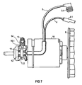
- FIG. 7 shows an axial top view of e.g. from the Electric motor known from DE 34 34 429 C2 and EP 0 708 519 B1 10, with one attached to the right rotor shaft end Fan wheel 9.
- the Electric motor known from DE 34 34 429 C2 and EP 0 708 519 B1
- the one not visible commutator here for feeding the rotor winding of the electric motor 10.
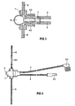
- 1-5 serve to explain the intermediate terminal board according to the invention 1; 2 with its advantageous contact and strain-relieved fixation of external motor connection cables 3; 4 and inner intermediate lines 5; 6 and at least a radio interference suppression component 7 in the form of a capacitor and, if appropriate a motor protection component 8 in the form of a varistor.
- the outer connecting lines are advantageous 3; 4 and the intermediate lines 5; 6 each Parts of a continuous one-piece motor connection cable 3; 4 or intermediate line 5; 6, which are only in the contacting area stripped the outer connector 3.1 or 4.1 is.
- an intermediate clipboard part 1 in the sense of a pre-assembly or pre-fixation by an insulating wall 1.3 separate receiving chambers for the Motor connection lines 3; 4 and with supplied from outside Recording requirements 1.2 for the angled outgoing Intermediate lines 5; 6 and with a receiving chamber 1.4 for a motor protection component 8 in the form of a varistor and a receiving chamber 1.5 for a radio interference suppression component 7 in Form a capacitor.
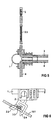
- second intermediate clipboard part 2 is the entire component unit by means of a snap connection 2.4 with a swivel support pad 2.5 on the electric motor 10 or the bracket 10.1 of the electric motor fixed; there is the ground potential in a manner known from EP 0 708 519 B1 leading motor connection line 3 or intermediate line 5 with one provided outside the intermediate terminal board 1; 2 stripped outer ground connection contact area 3.3 or 5.2 after bending back into one half-open cable receptacle 2.6 of the intermediate clipboard part 2 inserted and in its locking position against an electrical conductive motor housing part in the form of the bearing bracket 10.1 as a ground connection.
- FIG 4 finally shows a whole in a plan view fully assembled and assembled connection unit.
Landscapes
- Engineering & Computer Science (AREA)
- Power Engineering (AREA)
- Physics & Mathematics (AREA)
- Electromagnetism (AREA)
- Motor Or Generator Frames (AREA)
- Motor Or Generator Current Collectors (AREA)
Description
- FIG 1
- in einer perspektivischen Explosionsdarstellung ein zweiteiliges Zwischenklemmbrett mit einem Unterteil und einem damit verrastbaren Oberteil ohne Bestückung mit den zu kontaktierenden Bauteilen;
- FIG 2
- das gegenüber der Darstellung in FIG 1 derart gedrehte Oberteil, dass die Vormontage- bzw. Vorfixierungs-aufnahmen für die einzulegenden Kontaktierungsbauteile ersichtlich sind;
- FIG 3
- eine Draufsicht auf ein mit sämtlichen Kontaktierungsbauteilen vormontiertes Oberteil;
- FIG 4
- die Gesamtdraufsicht auf ein geschlossenes, mit sämtlichen Kontaktierungsbauteilen bestücktes Zwischenklemmbrett;
- FIG 5
- eine Draufsicht auf ein lediglich mit einer als Zwischenleitung weiterführenden durchgehenden äußeren Motor-Anschlussleitung vormontiertes Oberteil;
- FIG 6
- die Seitenansicht eines an einem Motorgehäuseteil verrasteten und dabei einen abisolierten äußeren Kontaktierungsbereich einer Motor-Anschlussleitung als Massenanschluss kontaktierenden Zwischenklemmbretts;
- FIG 7
- die axiale Draufsicht auf einen Lüftermotor mit einem in bekannter Weise am Lagerbügel eines Elektromotors gehaltenen Zwischenklemmbrett;
- FIG 8
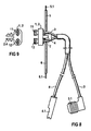
- in vergrößerter Draufsicht das mit sämtlichen Kontaktierungsbauteilen bestückte Zwischenklemmbrett aus FIG 5;
- FIG 9
- in einer axialen Draufsicht das Zwischenklemmbrett gemäß FIG 6.
Claims (9)
- Elektromotor, insbesondere Kommutatormotor,mit einem an einem Motorteil befestigbaren Zwischenklemmbrett (1;2) zur zugentlastenden Fixierung von äußeren Motor-Anschlussleitungen (3;4), die als Zwischenleitungen (5;6) zu Anschlüssen des Elektromotors (10) weiterführen;mit einer Ausbildung des Zwischenklemmbrettes (1;2) aus zwei unter Einschluss der zuvor einlegbaren Motor-Anschlussleitungen (3;4) bzw. Zwischenleitungen (5;6) im Sinne einer zugentlastenden Fixierung zusammendrückbaren und derart gegenseitig fixierbaren Zwischenklemmbrett-Teilen (1 bzw.2);mit einer Ausbildung des Zwischenklemmbrettes (1;2) zur zusätzlichen gegenseitigen Kontaktierung der äußeren Motor-Anschlussleitungen (3;4) bzw. Zwischenleitungen (5;6) mit zumindest einem elektrischen Funkentstörbauteil (7);mit einer Benutzung des Zwischenklemmbrettes (1;2) als löt- bzw. vercrimpfreies Klemm-Kontaktierungsmittel zwischen gegenseitigen inneren Kontaktierungsbereichen (3.2;4.2) der äußeren Motor-Anschlussleitungen (3;4) bzw. der Zwischenleitungen (5;6) mit dem elektrischen Funkentstörbauteil (7).
- Elektromotor nach Anspruch 1mit einer Ausbildung der äußeren Motor-Anschlussleitungen (3;4) auch als Zwischenleitungen (5;6) in Form von jeweils durchgehenden isolierten, jedoch jeweils in ihrem Kontaktierungsbereich (3.2;4.2) innerhalb des Zwischenklemmbrettes (1;2) abisolierten Leitungen.
- Elektromotor nach Anspruch 1 und/oder 2mit einem abisolierten äußeren Kontaktierungsbereich (3.3 bzw.5.2) im Verlauf einer der äußeren Motor-Anschlussleitungen (3;4) bzw. der Zwischenleitungen (5;6) nach ihrem Austritt aus dem Zwischenklemmbrett (1;2) zur Verbindung mit einem Masseanschluss, insbesondere einem elektrisch leitenden Teil des Elektromotors (10).
- Elektromotor nach zumindest einem der Ansprüche 1-3mit einer Ausbildung eines der beiden Zwischenklemmbrett-Teile (1 bzw.2) im Sinne einer Vormontage- bzw. Vorfixierungsaufnahme zumindest der Kontaktierungsbereiche (3.2;4.2) der Motor-Anschlussleitungen (3;4) bzw. Zwischenleitungen (5;6).
- Elektromotor nach zumindest einem der Ansprüche 1-4mit einer Ausbildung des zweiten Zwischenklemmbrett-Teils (2) im Sinne eines unter der Klemm-Kontaktierung mit dem ersten Zwischenklemmbrett-Teil (1) zusammensteckbaren, insbesondere verrastbaren, korrespondierenden Bauteil.
- Elektromotor nach zumindest einem der Ansprüche 1-5mit einer Ausbildung des Zwischenklemmbretts (1;2) als Kunststoffteil, insbesondere als Kunststoff-Spritzgußteil.
- Elektromotor nach zumindest einem der Ansprüche 1-6mit einer Halterung, insbesondere Rasthalterung (2.4), als Teil des Zwischenklemmbretts (1;2) zu dessen Fixierung an dem Elektromotor (10).
- Elektromotor nach zumindest einem der Ansprüche 1-7mit einem Funkentstörbauteil (7) in Form zumindest eines Kondensators.
- Elektromotor nach zumindest einem der Ansprüche 1-8mit einer zusätzlichen Klemm-Kontaktierung durch das Zwischenklemmbrett (1;2) für zumindest ein Motorschutzbauteil (8), insbesondere einen Varistor.
Applications Claiming Priority (5)
| Application Number | Priority Date | Filing Date | Title |
|---|---|---|---|
| DE10025272 | 2000-05-22 | ||
| DE10025272A DE10025272C1 (de) | 2000-05-22 | 2000-05-22 | Elektromotor mit Funkentstörung |
| DE20017576U DE20017576U1 (de) | 2000-10-13 | 2000-10-13 | Elektromotor, insbesondere Kommutatormotor |
| DE20017576U | 2000-10-13 | ||
| PCT/DE2001/001758 WO2001091268A1 (de) | 2000-05-22 | 2001-05-09 | Elektromotor, insbesondere kommutatormotor |
Publications (2)
| Publication Number | Publication Date |
|---|---|
| EP1285485A1 EP1285485A1 (de) | 2003-02-26 |
| EP1285485B1 true EP1285485B1 (de) | 2004-10-06 |
Family
ID=26005778
Family Applications (1)
| Application Number | Title | Priority Date | Filing Date |
|---|---|---|---|
| EP01944919A Expired - Lifetime EP1285485B1 (de) | 2000-05-22 | 2001-05-09 | Elektromotor, insbesondere kommutatormotor |
Country Status (4)
| Country | Link |
|---|---|
| EP (1) | EP1285485B1 (de) |
| DE (1) | DE50104005D1 (de) |
| ES (1) | ES2228892T3 (de) |
| WO (1) | WO2001091268A1 (de) |
Families Citing this family (1)
| Publication number | Priority date | Publication date | Assignee | Title |
|---|---|---|---|---|
| DE102008002729A1 (de) * | 2008-06-27 | 2009-12-31 | Robert Bosch Gmbh | Haltevorrichtung sowie damit ausgestatteter Elektromotor |
Family Cites Families (4)
| Publication number | Priority date | Publication date | Assignee | Title |
|---|---|---|---|---|
| DE3434429A1 (de) * | 1984-09-19 | 1986-03-20 | Siemens AG, 1000 Berlin und 8000 München | Entstoerter kommutator-motor |
| EP0504469B1 (de) * | 1991-03-22 | 1994-09-14 | Siemens Aktiengesellschaft | Elektrische Kontaktverbindung |
| DE4240381A1 (de) * | 1992-12-01 | 1994-06-09 | Licentia Gmbh | Elektromotor, insbesondere Kommutatormotor |
| EP0708519B1 (de) * | 1994-10-19 | 1997-03-19 | Siemens Aktiengesellschaft | Elektromotor, insbesondere Kommutatormotor, mit einem an einem Motorteil zugentlastet befestigbarem Zwischenklemmbrett |
-
2001
- 2001-05-09 DE DE50104005T patent/DE50104005D1/de not_active Expired - Lifetime
- 2001-05-09 EP EP01944919A patent/EP1285485B1/de not_active Expired - Lifetime
- 2001-05-09 ES ES01944919T patent/ES2228892T3/es not_active Expired - Lifetime
- 2001-05-09 WO PCT/DE2001/001758 patent/WO2001091268A1/de not_active Ceased
Also Published As
| Publication number | Publication date |
|---|---|
| ES2228892T3 (es) | 2005-04-16 |
| DE50104005D1 (de) | 2004-11-11 |
| WO2001091268A1 (de) | 2001-11-29 |
| EP1285485A1 (de) | 2003-02-26 |
Similar Documents
| Publication | Publication Date | Title |
|---|---|---|
| DE69812262T2 (de) | Elektrischer Kabelsteckverbinder | |
| DE69400053T2 (de) | Anordnung einer zweiteiligen Endkappe | |
| EP1944837A1 (de) | Anschluss für Potenzialausgleich | |
| EP1689065A1 (de) | "stator eines elektromotor" | |
| DE102016223844B4 (de) | Elektromotor und Kühlerlüftermodul mit einem solchen Elektromotor | |
| DE69206865T2 (de) | Miniaturmotor | |
| DE3447826C2 (de) | Elektro-Außenläufermotor | |
| DE202016102159U1 (de) | Kontaktierungsanordnung zwischen einem Stator und einer Leiterplatte | |
| DE10232281A1 (de) | Elektrische Anschlußanordnung | |
| DE20212273U1 (de) | Stator für einen Elektromotor | |
| EP0504469B1 (de) | Elektrische Kontaktverbindung | |
| DE69600844T2 (de) | Elektromotor-zusammenbau und elektrokontakt zur verwendung dafuer | |
| DE202006012075U1 (de) | Stator mit Schaltscheibe | |
| DE102005047479A1 (de) | Aufbau zum Verbinden eines Drahtes mit einer Elementaufnahmeeinheit | |
| EP0123213B1 (de) | Elektrisches Entstörfilter | |
| DE102018221859B4 (de) | Kommutatormotor und Baureihe von Kommutatormotoren | |
| EP1402615B1 (de) | Gehäuseteil für einen elektrischen verstellantrieb | |
| DE69111939T2 (de) | Leitende Hülse zum Klemmen auf einen abgeschirmten elektrischen Steckverbinder. | |
| DE29508111U1 (de) | Leistungskontaktierung für ein Stromrichtergerät | |
| EP1206008B1 (de) | Steckverbinder zum Anschliessen elektrischer Leitungen an eine elektrische Vorrichtung, insbesondere einen Motor | |
| DE69602143T2 (de) | Gehäuse für ein elektrisches Bauteil | |
| DE10025272C1 (de) | Elektromotor mit Funkentstörung | |
| EP1285485A1 (de) | Elektromotor, insbesondere kommutatormotor | |
| DE3434429C2 (de) | ||
| EP1665501B1 (de) | Elektromotor |
Legal Events
| Date | Code | Title | Description |
|---|---|---|---|
| PUAI | Public reference made under article 153(3) epc to a published international application that has entered the european phase |
Free format text: ORIGINAL CODE: 0009012 |
|
| 17P | Request for examination filed |
Effective date: 20020719 |
|
| AK | Designated contracting states |
Kind code of ref document: A1 Designated state(s): AT BE CH CY DE DK ES FI FR GB GR IE IT LI LU MC NL PT SE TR |
|
| GRAP | Despatch of communication of intention to grant a patent |
Free format text: ORIGINAL CODE: EPIDOSNIGR1 |
|
| RBV | Designated contracting states (corrected) |
Designated state(s): DE ES FR IT |
|
| GRAS | Grant fee paid |
Free format text: ORIGINAL CODE: EPIDOSNIGR3 |
|
| GRAA | (expected) grant |
Free format text: ORIGINAL CODE: 0009210 |
|
| AK | Designated contracting states |
Kind code of ref document: B1 Designated state(s): DE ES FR IT |
|
| REG | Reference to a national code |
Ref country code: IE Ref legal event code: FG4D Free format text: GERMAN |
|
| REF | Corresponds to: |
Ref document number: 50104005 Country of ref document: DE Date of ref document: 20041111 Kind code of ref document: P |
|
| REG | Reference to a national code |
Ref country code: ES Ref legal event code: FG2A Ref document number: 2228892 Country of ref document: ES Kind code of ref document: T3 |
|
| REG | Reference to a national code |
Ref country code: IE Ref legal event code: FD4D |
|
| PLBE | No opposition filed within time limit |
Free format text: ORIGINAL CODE: 0009261 |
|
| STAA | Information on the status of an ep patent application or granted ep patent |
Free format text: STATUS: NO OPPOSITION FILED WITHIN TIME LIMIT |
|
| ET | Fr: translation filed | ||
| 26N | No opposition filed |
Effective date: 20050707 |
|
| REG | Reference to a national code |
Ref country code: FR Ref legal event code: TP Owner name: BROSE FAHRZEUGTEILE GMBH & CO. KOMMANDITGESELL, DE Effective date: 20120125 |
|
| REG | Reference to a national code |
Ref country code: ES Ref legal event code: PC2A Owner name: BROSE FAHRZEUGTEILE GMBH & CO. KOMMANDITGESELLSCHA Effective date: 20120327 |
|
| PGFP | Annual fee paid to national office [announced via postgrant information from national office to epo] |
Ref country code: DE Payment date: 20120531 Year of fee payment: 12 |
|
| PGFP | Annual fee paid to national office [announced via postgrant information from national office to epo] |
Ref country code: ES Payment date: 20120607 Year of fee payment: 12 |
|
| PGFP | Annual fee paid to national office [announced via postgrant information from national office to epo] |
Ref country code: IT Payment date: 20130517 Year of fee payment: 13 Ref country code: FR Payment date: 20130531 Year of fee payment: 13 |
|
| PG25 | Lapsed in a contracting state [announced via postgrant information from national office to epo] |
Ref country code: DE Free format text: LAPSE BECAUSE OF NON-PAYMENT OF DUE FEES Effective date: 20131203 |
|
| REG | Reference to a national code |
Ref country code: DE Ref legal event code: R119 Ref document number: 50104005 Country of ref document: DE Effective date: 20131203 |
|
| REG | Reference to a national code |
Ref country code: ES Ref legal event code: FD2A Effective date: 20141010 |
|
| PG25 | Lapsed in a contracting state [announced via postgrant information from national office to epo] |
Ref country code: ES Free format text: LAPSE BECAUSE OF NON-PAYMENT OF DUE FEES Effective date: 20130510 |
|
| REG | Reference to a national code |
Ref country code: FR Ref legal event code: ST Effective date: 20150130 |
|
| PG25 | Lapsed in a contracting state [announced via postgrant information from national office to epo] |
Ref country code: IT Free format text: LAPSE BECAUSE OF NON-PAYMENT OF DUE FEES Effective date: 20140509 |
|
| PG25 | Lapsed in a contracting state [announced via postgrant information from national office to epo] |
Ref country code: FR Free format text: LAPSE BECAUSE OF NON-PAYMENT OF DUE FEES Effective date: 20140602 |