EP1285507B1 - Datenübertragungsverfahren - Google Patents
Datenübertragungsverfahren Download PDFInfo
- Publication number
- EP1285507B1 EP1285507B1 EP01927952A EP01927952A EP1285507B1 EP 1285507 B1 EP1285507 B1 EP 1285507B1 EP 01927952 A EP01927952 A EP 01927952A EP 01927952 A EP01927952 A EP 01927952A EP 1285507 B1 EP1285507 B1 EP 1285507B1
- Authority
- EP
- European Patent Office
- Prior art keywords
- transceiver
- quality class
- transmission
- estimate
- quality
- Prior art date
- Legal status (The legal status is an assumption and is not a legal conclusion. Google has not performed a legal analysis and makes no representation as to the accuracy of the status listed.)
- Expired - Lifetime
Links
Images

Classifications
-
- H—ELECTRICITY
- H04—ELECTRIC COMMUNICATION TECHNIQUE
- H04L—TRANSMISSION OF DIGITAL INFORMATION, e.g. TELEGRAPHIC COMMUNICATION
- H04L1/00—Arrangements for detecting or preventing errors in the information received
- H04L1/0001—Systems modifying transmission characteristics according to link quality, e.g. power backoff
- H04L1/0002—Systems modifying transmission characteristics according to link quality, e.g. power backoff by adapting the transmission rate
- H04L1/0003—Systems modifying transmission characteristics according to link quality, e.g. power backoff by adapting the transmission rate by switching between different modulation schemes
-
- H—ELECTRICITY
- H04—ELECTRIC COMMUNICATION TECHNIQUE
- H04B—TRANSMISSION
- H04B7/00—Radio transmission systems, i.e. using radiation field
- H04B7/02—Diversity systems; Multi-antenna system, i.e. transmission or reception using multiple antennas
- H04B7/04—Diversity systems; Multi-antenna system, i.e. transmission or reception using multiple antennas using two or more spaced independent antennas
- H04B7/06—Diversity systems; Multi-antenna system, i.e. transmission or reception using multiple antennas using two or more spaced independent antennas at the transmitting station
- H04B7/0613—Diversity systems; Multi-antenna system, i.e. transmission or reception using multiple antennas using two or more spaced independent antennas at the transmitting station using simultaneous transmission
- H04B7/0615—Diversity systems; Multi-antenna system, i.e. transmission or reception using multiple antennas using two or more spaced independent antennas at the transmitting station using simultaneous transmission of weighted versions of same signal
- H04B7/0619—Diversity systems; Multi-antenna system, i.e. transmission or reception using multiple antennas using two or more spaced independent antennas at the transmitting station using simultaneous transmission of weighted versions of same signal using feedback from receiving side
- H04B7/0621—Feedback content
- H04B7/0632—Channel quality parameters, e.g. channel quality indicator [CQI]
-
- H—ELECTRICITY
- H04—ELECTRIC COMMUNICATION TECHNIQUE
- H04L—TRANSMISSION OF DIGITAL INFORMATION, e.g. TELEGRAPHIC COMMUNICATION
- H04L1/00—Arrangements for detecting or preventing errors in the information received
- H04L1/0001—Systems modifying transmission characteristics according to link quality, e.g. power backoff
- H04L1/0023—Systems modifying transmission characteristics according to link quality, e.g. power backoff characterised by the signalling
- H04L1/0026—Transmission of channel quality indication
-
- H—ELECTRICITY
- H04—ELECTRIC COMMUNICATION TECHNIQUE
- H04L—TRANSMISSION OF DIGITAL INFORMATION, e.g. TELEGRAPHIC COMMUNICATION
- H04L1/00—Arrangements for detecting or preventing errors in the information received
- H04L1/02—Arrangements for detecting or preventing errors in the information received by diversity reception
- H04L1/06—Arrangements for detecting or preventing errors in the information received by diversity reception using space diversity
-
- H—ELECTRICITY
- H04—ELECTRIC COMMUNICATION TECHNIQUE
- H04L—TRANSMISSION OF DIGITAL INFORMATION, e.g. TELEGRAPHIC COMMUNICATION
- H04L1/00—Arrangements for detecting or preventing errors in the information received
- H04L1/20—Arrangements for detecting or preventing errors in the information received using signal quality detector
Definitions
- the invention relates to a method of increasing spectral efficiency and improving the performance of a radio link, particularly in transmission of high-rate packet data, for example in the Internet.
- MIMO systems Multiple Input - Multiple Output
- STTD Space-Time Transmit Diversity
- a signal is transmitted continuously to a subscriber terminal using at least two different antennas.
- the signal transmitted via the different antennas is different.
- time-space trellis codes and time-space block codes.
- trellis coding a trellis diagram is used, wherein each possible state and branches from it to other states are expressed by two symbols.
- the bits to be coded can be expressed in the trellis diagram by symbols indicating the transitions to be made between different levels. The obtained symbols are then distributed for transmission over different antennas.
- bits to be coded in space-time block codes are divided for example into two-bit sequences, of which the symbols to be transmitted are generated so that the symbol to be transmitted over a first antenna is generated from a first bit and the complex conjugate of a second bit, and the symbol to be transmitted over a second antenna is generated from a second bit and the complex conjugate of the first bit.
- the third and subsequent generations of mobile systems provide a chance to adapt the transfer rate according to the information to be transferred: speech is transferred at a lower rate, data at a faster rate and multimedia applications use the highest transfer rate.
- High transfer rates usually also require high transmission power in order to ensure the required quality on the connection.
- performance on the transmission path Is affected not only by compensation for the effects of a multipath propagation environment, but also for example the spectral efficiency of the transmission, i.e. the achievement of the required quality at as low a use of radio resources as possible, typically at as low a transmission power as possible. Besides requiring less current, low transmission power also interferes less with other system signals.
- US 5,886,987 presents a CDMA transmission/reception system used for a forward link in a mobile communications system.
- the system US 5,886,987 discloses provides an FDD/CDMA transmission/reception system which can realize transmission diversity and improve fading an interference resistance characteristics.
- the FDD/CDMA transmission/reception system comprises a CDMA transmitter and a CDMA receiver, the CDMA transmitter including a plurality of transmission antennas, signal transmission means for transmitting transmission signals weighted by different values to the respective transmission antennas and pilot signal transmission means for transmitting a plurality of different pilot signals to the respective transmission antennas and the CDMA receiver including reception means for obtaining one received signals from the transmission signals from the plurality of transmission antennas of the CDMA transmitter and means for transmitting antenna control signals corresponding to reception power values of the received pilot signals to the CDMA transmitter.
- EP 0987 842 discloses that in radio FDD communication, reception quality is measured at a communication terminal, the measurement result is reported to a base station, and the base station changes a transmission antenna based on the reported result on the reception quality. Thereby, in the FDD system, the transmission antenna can be determined based on a received signal.
- EP 0969 624 discloses a method for monitoring the quality of a transmission channel and a digital receiver.
- a signal is received from a transmission network, various data related to the operation of the transmission channel are measured from the received signal and the data are transferred through a return channel to a transmission centre.
- the transmission centre comprises a modem and a computer for processing measuring results for taking required actions to improve the quality of the transmission channel.
- WO 00 72464 presents a transmit diversity method for a wireless communication system comprising a transmitting element and at least one receiver, wherein a transmission signal is transmitted from the transmitting element to the at least one receiver in accordance with a weight information determined in response to a feedback information.
- the feedback information is derived from the response at the at least one receiver to the transmission signal, and is fed back using multiplexed feedback signals.
- Multiple feedback signal quantization constellation and/or constellation specific feedback subchannels can be used for channel probing.
- US 5,982,766 presents a power control method and system in a TDMA radio communication system.
- the power control system has traffic channels which are associated with a set of speech/channel encoding modes. Each mode has a different mix of speech encoder bit rate and data protection bit rate but the same total available gross bit rate.
- the transmitter includes a power control unit that replaces a mode allocated to a channel by another mode having either a higher or a lower data protection bit rate and either a lower or a higher speech encoder bit rate, if the sound to be encoded requires either a lower or higher speech encoding bit rate.
- the problem is to find as good a spectral efficiency as possible in multiple antenna systems, particularly at high transfer rates, for example in packet data transfer in the Internet.
- the object of the invention is thus to provide a method and equipment for implementing the method so as to achieve as good spectral efficiency and radio link performance as possible in multiple antenna systems at high transfer rates.
- the invention also relates to a data transfer method in a radio system comprising a first transceiver and a second transceiver, of which at least the first transceiver comprises a multiple antenna system, in which method a signal transmitted by the first transceiver is measured by the second transceiver, and in which method one or more threshold values are set on the performance of the transfer channel.
- the method of the invention comprises comparing a parameter value representing the quality of the signal measured by the second transceiver from the signal it received with one or more threshold values, and thus determining a quality class for the performance of a MIMO common channel, coding the determined quality class by the second transceiver, the second transceiver transmitting information on the quality class to the first transceiver, storing the observations made by the second transceiver about the quality class transitions of the transmission radio channel of the first transceiver, estimating the next quality class of the transmission radio channel of the first transceiver from the stored quality class transition observations, and determining the transmit parameters of the antenna elements of the multiple antenna system used by the first transceiver for transmission based on the estimate.
- the invention also relates to a radio system comprising a first transceiver having an associated multiple antenna system, in which radio system a second transceiver comprises means for measuring a received signal, and in which radio system at least one threshold value is set on the performance of the transfer channel.
- the second transceiver comprises means for comparing a parameter representing signal quality measured from the received signal with at least one threshold value, and means for determining a quality class for the performance of a MIMO common channel
- the second transceiver comprises means for encoding the determined quality class
- at least one of the transceivers comprises means for storing the observations made by the second transceiver about the quality class transitions of the transfer channel of the first transceiver
- at least one of the transceivers comprises means for estimating the next quality class of the transfer channel of the first transceiver from the stored quality class transition observations
- the second transceiver comprises means for transmitting quality class information or a quality class estimate to the first transceiver
- the first transceiver comprises means for determining the transmit parameters of the antenna elements of the multiple antenna system used by the first transceiver for transmission based on the quality class.
- the invention also relates to a transceiver of a radio system, the transceiver having an associated multiple antenna system, and in which radio system at least one threshold value is set on the performance of the transfer channel, the transceiver by comprising: means for storing observations made by another transceiver of the radio system about the quality class transitions of a transfer channel of said transceiver; means for estimating a next quality class of the transfer channel of said transceiver from quality class transition observations made by the other transceiver of the radio system; and means for determining transmit parameters of the antenna elements of the multiple antenna system based on the quality class.
- the invention also relates to a transceiver of a radio system, the transceiver comprising means for measuring a received signal, and in which radio system at least one threshold value is set on the performance of the transfer channel, the transceiver comprising: means for comparing a parameter representing signal quality measured from the received signal with at least one threshold value; and means for determining a quality class for the performance of a MIMO channel; means for estimating a next quality class of the transfer channel of the other transceiver from quality class transition observations; and means for transmitting a quality class estimate to another transceiver.
- the method and system of the invention provide a plurality of advantages.
- the method of the invention improves spectral efficiency and radio link performance.
- the method also enables adaptation of the transfer rate according to the information to be transferred.
- the method also enables the choice of a diversity antenna or only one antenna in transmission, allowing the diversity antenna to be used for example for the transmission of other data.
- the method also enables the choice of the number of antenna elements in an antenna array to be used for transmission.
- the method enables a decrease in the number of antennas of a radio system network part, such as a base station, used for transmission, and a decrease In the number of receiver branches in a subscriber terminal.
- the transfer of measurement data made by the subscriber terminal from a received signal also requires fewer bits and, consequently, less time, as the measurement data are encoded into quality class data, thus allowing more actual data to be transmitted.
- a further advantage is that the obtained quality class data can be utilized in the choice of transmit parameters, such as weighting coefficients used for antenna beam formation when utilizing multiple antenna systems.
- measurements by the subscriber terminal can be made less often, since the base station is able to calculate statistically what the radio channel is likely to be after a coherence time (the time the radio channel remains unchanged). This enables the transmission of more actual data.
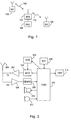
- FIG. 1 schematically shows a digital data transfer system, to which the solution of the invention is applicable.
- the system is a cellular radio system comprising a base station 104 that is in a bi-directional connection 108 and 110 with subscriber terminals 100 and 102 that are fixedly mounted, vehicle-mounted or hand-held portable terminals.
- the base station comprises transceivers that communicate with an antenna unit for implementing a bi-directional connection to the subscriber terminal.
- the base station communicates with a base station controller 106 that switches the connections of the terminals to other parts of the network.
- Several base stations communicating with the base station controller are controlled by it in a centralized manner.
- a control unit in the base station controller attends to call control, mobility management, gathering statistics, and signalling.
- a connection may exist also to a public telephone network, whereby a transcoder comprised by the system converts the different digital speech encoding forms used between the public telephone network and the cellular radio network into a form suitable for one another, for example from the 64-kbps form of the fixed network to another form of the cellular radio network (e.g. 13 kbps), and vice versa.
- a transcoder comprised by the system converts the different digital speech encoding forms used between the public telephone network and the cellular radio network into a form suitable for one another, for example from the 64-kbps form of the fixed network to another form of the cellular radio network (e.g. 13 kbps), and vice versa.
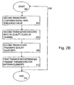
- Figure 2a shows a flow diagram of method steps required for increasing spectral efficiency when a first transceiver in a system is a network part, e.g. a base station, and a second transceiver is a subscriber terminal. It should be noted that the method is also applicable when the first transceiver is a subscriber terminal and the second a network part.
- the method starts at block 200.
- the subscriber terminal compares a signal transmitted by a base station with a threshold value stored in advance in a subscriber terminal. There may be one or more threshold values. The more exact the determination of the signal quality class is to be, the more threshold values there should naturally be, since the threshold values are required to separate the different quality classes from each other.
- the subscriber terminal In determining the quality of a MIMO channel, i.e. the common channel formed by channels 1 and 2 in the example shown, the subscriber terminal utilizes for example a pilot signal transmitted by a network part in the radio system, such as a base station, or a known symbol sequence. The attempt is to select the pilot signals transmitted by each antenna element such that they are mutually orthogonal, i.e. do not correlate. Measurements, such as calculation of bit error ratio values, determination of signal-to-interference ratio (SIR) or determination of received signal power, performed at present by a subscriber terminal, may be utilized in the determination of the quality of the signal received by the subscriber terminal.
- SIR signal-to-interference ratio
- FCSC Finite Channel State Classification information, which is an encoded quality class, or state determination, of the common channel.
- FCSC refers to a quality class encoding method. Quality of channel FSCS Quality class Channel 1 good and channel 2 good 11 S 1 Channel 1 bad and channel 2 good 01 S 2 Channel 1 good and channel 2 bad 10 S 3 Channel 1 bad and channel 2 bad 00 S 4
- the accuracy of the indication of the quality class of the common channel is to be determined.
- the accuracy of the indication of the quality class of the common channel is to be determined.
- the application of the method does not restrict the number of quality classes, which can be selected suitable depending on the application, based on how many channels the MIMO system comprises, how accurately the signal quality class is to be determined, i.e. the number of quality class threshold values, and how many bits are usable for indicating the quality class.
- the encoding needed in the example of the table is very simple binary coding: 1 means a good channel and 0 a bad channel.
- the coding method can also be selected as desired application-specifically.
- the subscriber terminal sends the encoded quality class information to a network part of the radio system, such as a base station. Transmission is not necessarily continuous, but may also take place periodically.
- Constant K expresses the number of different quality classes.
- a transition probability matrix TMP is calculated, which in this case is a KxK matrix, whose elements are composed of the probabilities of different state transitions.
- Variables P ij express the probability of a transition from state i to state j, i.e. from quality class i to quality class j.
- p ij n number of transitions S i ⁇ S j in last n observations number of transitions S i ⁇ in last n observations i.e. the number of transitions from a quality class, i.e. state S i to quality class S j , in the last n observations divided by the number of all transitions from quality class S i in the last n observations.
- the transition probability matrix can be preferably updated after transmission of quality class determination information by each subscriber terminal or less frequently.
- the transition probability matrix is updated such that all dividers on the i th row are incremented by one and the dividend of the j th element is incremented by one.
- the observations stored in block 208 can be used for a statistical prognosis about the most probable subsequent radio channel quality class, see block 210.
- the following radio channel quality class is good at a very high probability, i.e. in this example S 1
- packet data is concerned, it is preferable to send a plurality of data packets.
- multiple-layer modulation may be used and thus increase the transfer rate.
- a lighter encoding or no encoding at all may also be used, which also increases data transfer rate.
- the channel it preferable to wait for the channel to improve, e.g. the duration of the coherence time of the channel, before starting transmission. This way no attempts are made to transmit at a high power thus interfering with other users of the system.
- a more efficient encoding or modulation method may also be used, which only comprises a few levels, e.g. binary modulation only comprises two levels.
- weighting of the input signals of the antenna elements can for example be used, favouring the better antenna element.
- the network part in the radio system should preferably arrange its transmissions for example when packet data is concerned such that data transfer requiring a high transfer rate is not transmitted until information about an improvement of the channel is received.
- the transmit parameters of the antenna elements used for transmission are determined, preferably transmission power. If zero power is selected, said antenna element is not used.
- the diversity combination to be used may also be selected, e.g. if diversity is used, and if so, what diversity antennas or diversity methods are used.
- the method ends at block 214. Arrow 218 shows how the method can be repeated when needed. Typically, the method is executed several times during transmission.
- the method may also be simplified.
- Method steps 200 to 206 are similar to those described above, and will not be repeated.
- the embodiments described differ from one another in that in the embodiment shown in Figure 2b, after block 206, the transmit parameters are determined for the antenna elements to be used for transmission, preferably transmission power 212.
- the method ends at block 214.
- This simpler application is faster, but is based at each particular time only on the latest channel quality class determination and is thus more susceptible to error values than the application according to Figure 2a, which utilizes statistical analysis.
- a first transceiver produces the described statistical class transition prognosis.
- the method is also applicable such that the second transceiver performs the statistical analysis and transmits the prognosis to the first transceiver.
- Figure 3 illustrates a terminal for implementing the method shown in Figures 2a-b in a radio system.
- the transmitter of the subscriber terminal and the transmitter of a network part in the radio system partly perform the same tasks, which will be described in detail later when describing the structure of the transmitter of the network part.
- the terminal may be for example a portable telephone or a personal computer, without any restriction thereto.
- the terminal comprises an antenna 300 for transmitting and receiving signals via a duplex filter.
- the terminal may also comprise several antennas or a multiple antenna system.
- the terminal also comprises a transmitter 302 for amplifying and transmitting a modulated signal to the antenna, a modulator 304 for modulating the carrier with a data signal containing the desired information in accordance with the selected modulation method, a receiver 306 for amplifying a signal coming from the antenna and for down-converting it into a selected intermediate frequency or directly into the base frequency, a demodulator 308 for demodulating a received signal so that the data signal can be separated from the carrier.
- a transmitter 302 for amplifying and transmitting a modulated signal to the antenna
- a modulator 304 for modulating the carrier with a data signal containing the desired information in accordance with the selected modulation method
- a receiver 306 for amplifying a signal coming from the antenna and for down-converting it into a selected intermediate frequency or directly into the base frequency
- a demodulator 308 for demodulating a received signal so that the data signal can be separated from the carrier.
- the subscriber terminal also comprises a control block 316 for controlling the operation of the different parts of the terminal and performing necessary measures to process user speech or data generated by the user, such as DSP processing (Digital Signal Processing), D/A conversion and filtering.
- the control block also performs both encoding and decoding, such as channel and speech encoding.
- a pseudo-random spreading code can be used to spread signal spectrum in the transmitter to a wide band and despread it in the receiver, thus aiming at increasing the capacity of the channel.
- the control block also adapts the signal and signalling information to be transmitted to make it conform to the air interface standard of the radio system used.
- the control block also comprises a program for controlling the operation of the terminal.
- the control block performs measurements, such as bit error ratio measurements and power measurement, required for quality class determination of the signal transmitted by a network part in the radio system.
- the control block also compares the measured value with the stored threshold value(s).
- the terminal also comprises a buffer memory 318, wherein at least one predetermined quality class threshold value is stored.
- the quality class threshold values may also be changed. Typically, in the selection of a quality class threshold value, for example the radio environment, the radio system used and the number of antennas are taken into account.
- the quality class obtained by comparison is encoded for example as described in context with Figure 2 or in some other suitable way in an encoding block 320.
- the encoded quality class definition is transmitted via the transmitter part of the subscriber terminal to a network part in the radio system.
- a terminal such as the control block and the encoding block
- a terminal can be implemented in many ways, for example by software executed with a processor or a hardware application, such as logics built from separate components or ASIC (Application Specific Integrated Circuit).
- ASIC Application Specific Integrated Circuit
- the user interface of the terminal comprises a speaker or an earpiece 310, a microphone 312, a display 314 and optionally a keyboard, which communicate with the control block.
- a multiple antenna system such as an antenna array, which is able to use directional antenna beams, comprises several separate, e.g. eight, antenna elements.
- the figure only shows two, 400A, 400B.
- the same antenna elements as in transmission can be used in reception, or there can be a separate antenna element 400C for transmission in the manner shown in Figure 2.
- the receiver may also comprise several antenna elements.
- the antenna element arrangement is for example linear or planar.
- the elements may be arranged for example as a ULA (Uniform Linear Array), wherein the elements are arranged at regular intervals on a straight line.
- Planar refers to for example CA (Circular Array), wherein the elements are arranged on the same plane for example horizontally in the form of the periphery of a circle. In this case a given portion of the periphery of the circle is covered, e.g. 120 degrees, even the entire 360 degrees.
- said uniplanar antenna structures can be used to build two-dimensional and even three-dimensional structures.
- a two-dimensional structure is formed for example by placing ULA structures in parallel, whereby the elements form a matrix.
- a multipath propagated signal is received via the antenna elements.
- Each antenna element comprises a receiver, in the figure only one 402, which are radio frequency parts.
- the receiver of a network part in a radio system has to be able to receive and disassemble into a bit stream the data transmitted by a terminal about the quality class of the signal transmitted by a base station.
- Storage and processing of the quality class information in the transceiver of the network part in the radio system can also be placed on the receiver side 404, but in this example the structures carrying out said functions are placed on the transmitter side and will be described later in connection with the description of the transmitter structure.
- the receiver 402 comprises a filter for elimination of frequencies outside the desired frequency band.
- the signal is then converted into an intermediate frequency or directly to the base frequency, in which form the signal is sampled and quantized in an analog/digital converter 406.
- a demodulator 408 removes the carrier from the received signal and any spreading coding used in a spread spectrum system.
- the demodulation block also performs different signal processing tasks, such as channel decoding, deinterleaving and decryption.
- the transmitter of the network part in the radio system comprises a modulation block 414 for modulating the carrier by a modulation method selected with a data signal including the desired information.
- the modulation block processes the user's speech or data generated by the user, such as DSP processing (Digital Signal Processing), which is used for example for encoding and encrypting information to be transmitted.
- DSP processing Digital Signal Processing
- channel coding systematic bit redundancy, typically parity bits, are added to the signal and used for error detection and correction in the decoder.
- speech encoding asymmetric redundancy is typically removed from source symbols to lower the required bit rate.
- WCDMA spread spectrum of a signal is spread by means of a pseudo-random spreading code to a wide band in the transmitter.
- the transmitter comprises D/A converters 420 and 420a-b for converting a digital signal into analog.
- the transmitter also comprises RF parts 422 and 422a-b, in which the signal is up-converted to the selected transmission frequency.
- the RF parts also comprise filters, which in band-restricted systems restrict the bandwidth of the transmission in the transmitter and amplifiers for amplifying a signal to be transmitted to the selected power level.
- the transmitter also adapts the signal to be transmitted and the signalling information so that they conform to the air interface standard of the radio system used.
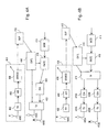
- Figure 4a illustrates the structure of a transmitter of a network part in a radio system, with no weighing of the input signals of the antennas. It should also be noted that in the simplest embodiment of the invention, no means 412 are needed for storing the quality class observations made by the terminal from the signal received from the network part and for statistical prognosis of the following transition.
- a control block 410 controls means 416 for selecting the rate for selecting a suitable transfer rate taking the quality of the connection into account. If the connection is bad, a lower transfer rate is used. However, the method can also be utilized without the means 416 for selecting the transfer rate. The transfer rate can also be affected with the number of antenna elements used for transmission: the more antenna elements are usable for transmission, the higher is the transfer rate achieved. When the channel is bad, packet data can also be retransmitted a sufficient number of times.
- the control block 410 also controls RF parts 422 and thereby the selection of the antenna elements 400a-b, in order for a sufficiently bad channel to be left entirely unused until information about an improvement in the state of the channel is received from the subscriber terminal. However, if the channel is fit for transfer, the transfer connection can be improved by raising transmission power. However, in raising power, it should be born in mind that it causes an increasing amount of interference to other channels.
- Figure 4b illustrates the structure of a transceiver of a network part in a radio system, when the input signals of antenna elements are multiplied by weighting coefficients selected in weighting means.
- the structure and function of the transceiver correspond to the weighting means and except from the number of RF parts the situation shown in Figure 4a, so only those structural parts will be described herein that are different in Figure 4b than in 4a.
- the weighting means 418 a signal going to each antenna element is multiplied by a typically complex coefficient corresponding to each antenna element.
- the antenna beam can be directed in the direction of a complex vector formed by elements or by selecting the weighting coefficient zero, one or more antennas can be left unused.
- the control block 410 controls the operation of the weighting means on the basis of quality class information obtained from the subscriber terminal.
- the control block 410 also controls RF parts 422a-b and thereby the selection of antenna elements 400a-b, in order that a sufficiently bad channel can be left totally unused until information about an improvement in the state of the channel is received from the subscriber terminal.
- the transfer connection can be improved by increasing transmission power.
- a network part of a radio system such as a base station or a transceiver, e.g. the control block, the transfer rate selection means and the weighting means, can be implemented in many ways, for example with software executed with a processor or a hardware implementation, such as logics circuits built of separate components or ASIC.
Landscapes
- Engineering & Computer Science (AREA)
- Computer Networks & Wireless Communication (AREA)
- Signal Processing (AREA)
- Quality & Reliability (AREA)
- Mobile Radio Communication Systems (AREA)
- Radio Transmission System (AREA)
- Communication Control (AREA)
- Photoreceptors In Electrophotography (AREA)
- Transceivers (AREA)
Claims (33)
- Datenübertragungsverfahren in einem Funksystem, umfassend einen ersten Sendeempfänger und einen zweiten Sendeempfänger, von denen mindestens der erste Sendeempfänger ein Mehrfachantennensystem umfasst, wobei in diesem Verfahren ein durch den ersten Sendeempfänger übertragenes Signal durch den zweiten Sendeempfänger gemessen wird, und wobei in diesem Verfahren ein oder mehr Schwellenwerte auf die Leistungsfähigkeit des Übertragungskanals eingestellt sind, gekennzeichnet durch
das Vergleichen (202) eines Parameterwerts, der die Qualität des Signals darstellt, das durch den zweiten Sendeempfänger aus dem von ihm empfangenen Signal mit einem oder mehr Schwellenwerten gemessen wird und auf diese Weise eine Qualitätsklasse für die Leistung eines gemeinsamen MIMO-Kanals bestimmt wird;
das Codieren (204) der bestimmten Qualitätsklasse durch den zweiten Sendeempfänger;
das Senden (206) der Information zur Qualitätsklasse vom zweiten Sendeempfänger zum ersten Sendeempfänger;
das Speichern (208) der durch den zweiten Sendeempfänger gemachten Beobachtungen zu Qualitätsklasseübergängen des Funkkanals für das Senden des ersten Sendeempfängers ;
das Schätzen (210) der nächsten Qualitätsklasse des Funkkanals für das Senden des ersten Sendeempfängers aus den Beobachtungen zu den gespeicherten Qualitätsklasseübergängen;
das Bestimmen (212) der Sendeparameter der Antennenelemente des Mehrfachantennensystems, die durch den ersten Sendeempfänger für das Senden auf der Basis der Schätzung benutzt werden. - Verfahren nach Anspruch 1, dadurch gekennzeichnet, dass der erste Sendeempfänger ein Netzwerkabschnitt (104) im Funksystem ist und der zweite Sendeempfänger ein Teilnehmeranschluss (100, 102) ist.
- Verfahren nach Anspruch 1, dadurch gekennzeichnet, dass der erste Sendeempfänger ein Teilnehmeranschluss (100, 102) ist und der zweite Sendeempfänger ein Netzwerkabschnitt (104) im Funksystem ist.
- Verfahren nach Anspruch 2 oder 3, dadurch gekennzeichnet, dass die Sendeleistung der Antennenelemente im Mehrfachantennensystem, die durch den ersten Sendeempfänger für das Senden auf der Basis der Schätzung benutzt werden, bestimmt wird.
- Verfahren nach Anspruch 2 oder 3, dadurch gekennzeichnet, dass das Eingangssignal jedes Antennenelements, das zum ersten Sendeempfänger auf der Basis der Schätzung gehört, gewichtet wird.
- Verfahren nach Anspruch 2 oder 3, dadurch gekennzeichnet, dass die Leistung des Signals, welches vom zweiten Sendeempfänger als einen Parameter darstellende Qualität empfangen wird, gemessen wird.
- Verfahren nach Anspruch 2 oder 3, dadurch gekennzeichnet, dass die Bitfehlerrate des Signals, das durch den zweiten Sendeempfänger als einen Parameter darstellende Qualität empfangen wird, gemessen wird.
- Verfahren nach Anspruch 2 oder 3, dadurch gekennzeichnet, dass das Signal-Rausch-Verhältnis des Signals, das durch den zweiten Sendeempfänger als einen Parameter darstellende Qualität empfangen wird, gemessen wird.
- Verfahren nach Anspruch 2 oder 3, dadurch gekennzeichnet, dass das verursachte Rauschen reduziert wird, indem keine Funkkanäle einer schlechten Qualitätsklasse für das Senden des Sendeempfängers benutzt werden.
- Verfahren nach Anspruch 2 oder 3, dadurch gekennzeichnet, dass die Übertragungsrate des Sendens des ersten Sendeempfängers mittels der Schätzung bestimmt wird.
- Verfahren nach Anspruch 2 oder 3, dadurch gekennzeichnet, dass eine geeignete Diversitätskombination für das Senden des ersten Sendeempfängers mittels der Schätzung bestimmt wird.
- Verfahren nach Anspruch 2 oder 3, dadurch gekennzeichnet, dass die Reihenfolge der mittels der Schätzung zu sendenden Datenpakete bestimmt wird.
- Verfahren nach Anspruch 2 oder 3, dadurch gekennzeichnet, dass ein geeignetes Modulationsverfahren für das Senden des ersten Sendeempfängers mittels der Schätzung ausgewählt wird.
- Verfahren nach Anspruch 2 oder 3, dadurch gekennzeichnet, dass ein geeignetes Codierverfahren für das Senden des ersten Sendeempfängers mittels der Schätzung ausgewählt wird.
- Verfahren nach Anspruch 2 oder 3, dadurch gekennzeichnet, dass eine geeignete Codiertiefe für das Senden des ersten Sendeempfängers mittels der Schätzung ausgewählt wird.
- Funksystem mit einem ersten Sendeempfänger, der ein zugeordnetes Mehrfachantennensystem aufweist, wobei in dem Funksystem ein zweiter Sendeempfänger Mittel (314, 316) zum Messen eines empfangenen Signals umfasst und wobei in dem Funksystem mindestens ein Schwellenwert auf die Leistungsfähigkeit des Übertragungskanals eingestellt ist, dadurch gekennzeichnet, dass
der zweite Sendeempfänger Mittel (316, 319) zum Vergleichen eines Parameters umfasst, der die aus dem empfangenen Signal mit mindestens einem Schwellenwert gemessene Signalqualität darstellt und Mittel (316, 318) zum Bestimmen einer Qualitätsklasse für die Leistung eines gemeinsamen MIMO-Kanals; der zweite Sendeempfänger Mittel (320) zum Codieren der bestimmten Qualitätsklasse umfasst;
mindestens einer der Sendeempfänger Mittel (318, 412) zum Speichern der durch den zweiten Sendeempfänger gemachten Beobachtung zu den Qualitätsklasseübergängen des Übertragungskanals des ersten Sendeempfängers umfasst;
mindestens einer der Sendeempfänger Mittel (318, 412) zum Schätzen der nächsten Qualitätsklasse des Übertragungskanals des ersten Sendeempfänger aus den gespeicherten Beobachtungen zum Qualitätsklasseübergang umfasst;
der zweite Sendeempfänger Mittel (316, 304, 302, 300) zum Senden von Qualitätsklasseinformation oder eine Qualitätsklasseschätzung zum ersten Sendeempfänger umfasst;
der erste Sendeempfänger Mittel (410, 418, 422) zum Bestimmen der Sendeparameter der Antennenelemente des Mehrfachantennensystems umfasst, die vom ersten Sendeempfänger zum Senden auf der Basis der Qualitätsklasse benutzt werden. - System nach Anspruch 16, dadurch gekennzeichnet, dass der erste Sendeempfänger ein Netzwerkabschnitt (104) im Funksystem ist und der zweite Sendeempfänger ein Teilnehmeranschluss (100, 102) ist.
- System nach Anspruch 16, dadurch gekennzeichnet, dass der erste Sendeempfänger ein Teilnehmeranschluss (100, 102) ist und der zweite Sendeempfänger ein Netzwerkabschnitt (104) im Funksystem ist.
- System nach Anspruch 17 oder 18, dadurch gekennzeichnet, dass der erste Sendeempfänger Mittel (410, 422) zum Bestimmen der Sendeleistung der Antennenelemente im Mehrfachantennensystem auf der Basis der Schätzung umfasst.
- System nach Anspruch 17 oder 18, dadurch gekennzeichnet, dass der erste Sendeempfänger Mittel (410, 418) zum Wichten des Eingangssignals jedes Antennenelements des Mehrfachantennensystems auf der Basis der Schätzung umfasst.
- System nach Anspruch 17 oder 18, dadurch gekennzeichnet, dass der zweite Sendeempfänger Mittel (316) zum Messen der Leistung des empfangenen Signals als einen Qualität darstellenden Parameter umfasst.
- System nach Anspruch 17 oder 18, dadurch gekennzeichnet, dass der zweite Sendeempfänger Mittel (314, 316) zum Messen der Bitfehlerrate des empfangenen Signals als einen Qualität darstellenden Parameter umfasst.
- System nach Anspruch 17 oder 18, dadurch gekennzeichnet, dass der zweite Sende-Empfänge Mittel (314, 316) zum Messen des Signal-Rausch-Verhältnisses des empfangenen Signals als einen Qualität darstellenden Parameter umfasst.
- System nach Anspruch 17 oder 18, dadurch gekennzeichnet, dass der erste Sendeempfänger weniger Rauschen verursachende Mittel (410, 418, 422) umfasst, indem keine Funkkanäle schlechter Qualität für das Senden benutzt werden.
- System nach Anspruch 17 oder 18, dadurch gekennzeichnet, dass der erste Sendeempfänger Mittel (410, 416) zum Bestimmen der Übertragungsrate des Sendens mittels der Schätzung umfasst.
- System nach Anspruch 17 oder 18, dadurch gekennzeichnet, dass der erste Sendeempfänger Mittel (410, 416) zum Bestimmen einer geeigneten Diversitätskombination für das Senden mittels der Schätzung umfasst.
- System nach Anspruch 17 oder 18, dadurch gekennzeichnet, dass der Sendeempfänger Mittel (410) zum Bestimmen der Reihenfolge der mittels der Schätzung zu sendenden Datenpakete umfasst.
- System nach Anspruch 17 oder 18, dadurch gekennzeichnet, dass der erste Sendeempfänger Mittel (410, 414) zum Auswählen eines geeigneten Modulationsverfahrens für das Senden mittels der Schätzung umfasst.
- System nach Anspruch 17 oder 18, dadurch gekennzeichnet, dass der erste Sendeempfänger Mittel (410, 414) zum Auswählen eines geeigneten Codierverfahrens für das Senden mittels der Schätzung umfasst.
- System nach Anspruch 17 oder 18, dadurch gekennzeichnet, dass der ersten Sendeempfänger Mittel (410, 14) zum Auswählen einer geeigneten Codiertiefe für das Senden mittels der Schätzung umfasst.
- Sendeempfänger eines Funksystems, wobei der Sendeempfänger ein zugeordnetes Mehrfachantennensystem aufweist und wobei in dem Funksystems mindestens ein Schwellenwert auf die Leistungsfähigkeit des Übertragungskanals eingestellt ist, indem es umfasst:Mittel (318, 412) zum Speichern von Beobachtungen, die durch einen anderen Sendeempfänger des Funksystems zu den Qualitätsklasseübergängen eines Übertragungskanals des Sendeempfängers gemacht werden;Mittel (318, 412) zum Schätzen einer nächsten Qualitätsklasse des Übertragungskanals des Sendeempfängers aus Beobachtungen zum Qualitätsklasseübergang, die durch den anderen Sendeempfänger des Funksystems gemacht werden, undMittel (410, 418, 422) zum Bestimmen von Sendeparametern der Antennenelemente des Mehrfachantennensystems auf der Basis der Qualitätsklasse.
- Sendeempfänger eines Funksystems, wobei der Sendeempfänger Mittel (314, 316) zum Messen eines empfangenen Signals umfasst und wobei in dem Funksystem mindestens ein Schwellenwert auf die Leistungsfähigkeit des Übertragungskanals eingestellt ist, wobei der Sendeempfänger dadurch gekennzeichnet ist, dass er umfasst:Mittel (316, 318) zum Vergleichen eines Signalqualität darstellenden Parameters, der aus dem empfangenen Signal mit mindestens einem Schwellenwert gemessen wird;Mittel (316, 318) zum Bestimmen einer Qualitätsklasse für die Leistungsfähigkeit eines MIMO-kanals;Mittel (318, 412) zum Schätzen einer nächsten Qualitätsklasse des Übertragungskanals eines anderen Sendeempfängers aus den Beobachtungen zum Qualitätsklasseübergang undMittel (300, 302, 304, 316) zum Senden einer Qualitätsklasseschätzung zum anderen Sendeempfänger.
- Sendeempfänger nach Anspruch 32, dadurch gekennzeichnet, dass er ferner Mittel (318, 412) zum Speichern von Beobachtungen zu den Qualitätsklasseübergängen eines Übertragungskanals des anderen Sendeempfängers des Funksystems umfasst.
Applications Claiming Priority (3)
| Application Number | Priority Date | Filing Date | Title |
|---|---|---|---|
| FI20000853A FI20000853A7 (fi) | 2000-04-10 | 2000-04-10 | Tiedonsiirtomenetelmä |
| FI20000853 | 2000-04-10 | ||
| PCT/FI2001/000348 WO2001078220A1 (en) | 2000-04-10 | 2001-04-09 | Data transfer method |
Publications (2)
| Publication Number | Publication Date |
|---|---|
| EP1285507A2 EP1285507A2 (de) | 2003-02-26 |
| EP1285507B1 true EP1285507B1 (de) | 2007-11-14 |
Family
ID=8558171
Family Applications (1)
| Application Number | Title | Priority Date | Filing Date |
|---|---|---|---|
| EP01927952A Expired - Lifetime EP1285507B1 (de) | 2000-04-10 | 2001-04-09 | Datenübertragungsverfahren |
Country Status (7)
| Country | Link |
|---|---|
| US (1) | US7230928B2 (de) |
| EP (1) | EP1285507B1 (de) |
| AT (1) | ATE378745T1 (de) |
| AU (1) | AU2001254838A1 (de) |
| DE (1) | DE60131391T2 (de) |
| FI (1) | FI20000853A7 (de) |
| WO (1) | WO2001078220A1 (de) |
Families Citing this family (26)
| Publication number | Priority date | Publication date | Assignee | Title |
|---|---|---|---|---|
| GB0125178D0 (en) * | 2001-10-19 | 2001-12-12 | Koninkl Philips Electronics Nv | Method of operating a wireless communication system |
| EP1359697A1 (de) * | 2002-04-30 | 2003-11-05 | Psytechnics Ltd | Verfahren und Einrichtung zur Beschreibung von Übertragungsfehlern |
| EP1359698B1 (de) * | 2002-04-30 | 2005-01-12 | Psytechnics Ltd | Verfahren und Einrichtung zur Beschreibung von Übertragungsfehlern |
| KR100548312B1 (ko) * | 2002-06-20 | 2006-02-02 | 엘지전자 주식회사 | 다중 입출력 이동 통신 시스템에서의 신호 처리 방법 |
| US7542446B2 (en) * | 2002-07-31 | 2009-06-02 | Mitsubishi Electric Research Laboratories, Inc. | Space time transmit diversity with subgroup rate control and subgroup antenna selection in multi-input multi-output communications systems |
| JP3643360B2 (ja) | 2002-08-12 | 2005-04-27 | 松下電器産業株式会社 | 受信装置及び通信方法 |
| US7209712B2 (en) * | 2002-09-23 | 2007-04-24 | Qualcomm, Incorporated | Mean square estimation of channel quality measure |
| US7424270B2 (en) * | 2002-09-25 | 2008-09-09 | Qualcomm Incorporated | Feedback decoding techniques in a wireless communications system |
| US8149810B1 (en) * | 2003-02-14 | 2012-04-03 | Marvell International Ltd. | Data rate adaptation in multiple-in-multiple-out systems |
| US7864678B1 (en) | 2003-08-12 | 2011-01-04 | Marvell International Ltd. | Rate adaptation in wireless systems |
| US7616698B2 (en) | 2003-11-04 | 2009-11-10 | Atheros Communications, Inc. | Multiple-input multiple output system and method |
| KR20050075477A (ko) * | 2004-01-15 | 2005-07-21 | 삼성전자주식회사 | Mimo 스테이션 간에 통신하는 방법 |
| US7697449B1 (en) | 2004-07-20 | 2010-04-13 | Marvell International Ltd. | Adaptively determining a data rate of packetized information transmission over a wireless channel |
| US8131300B2 (en) * | 2004-04-28 | 2012-03-06 | Motorola Solutions, Inc. | Routing protocol within hybrid-cellular networks |
| EP1843502A4 (de) * | 2005-01-25 | 2012-05-23 | Panasonic Corp | Übertragungsvorrichtung und übertragungsverfahren |
| US7429904B2 (en) * | 2005-10-28 | 2008-09-30 | Avago Technologies Wireless Ip (Singapore) Pte Ltd | Spread-spectrum radio utilizing MEMS components |
| US9059866B2 (en) * | 2005-12-30 | 2015-06-16 | Remec Broadband Wireless Holdings, Inc. | Digital microwave radio system and method with encryption |
| US8711888B2 (en) * | 2005-12-30 | 2014-04-29 | Remec Broadband Wireless Llc | Digital microwave radio link with adaptive data rate |
| US8731007B2 (en) | 2005-12-30 | 2014-05-20 | Remec Broadband Wireless, Llc | Digital microwave radio link with a variety of ports |
| FI20065242A0 (fi) * | 2006-04-19 | 2006-04-19 | Nokia Corp | Vastaanotin ja vastaanottomenetelmä |
| CN101094022B (zh) * | 2006-06-19 | 2012-12-19 | 联想(北京)有限公司 | 发射机、通信系统以及通信方法 |
| US7792084B2 (en) * | 2006-08-29 | 2010-09-07 | Panasonic Corporation | MIMO antenna apparatus controlling number of streams and modulation and demodulation method |
| US8160601B2 (en) * | 2007-06-21 | 2012-04-17 | Elektrobit Wireless Communications Ltd. | Method for optimizing spatial modulation in a wireless link and network element thereto |
| US8588709B2 (en) * | 2009-12-18 | 2013-11-19 | Electronics And Telecommunications Research Institute | Switching apparatus and method for wireless communication system |
| US9301313B2 (en) * | 2011-06-13 | 2016-03-29 | Alcatel Lucent | Method and apparatus for data transmission with user selection |
| US20140179235A1 (en) * | 2012-12-20 | 2014-06-26 | Mediatek Inc. | Method for reducing power consumption and communications apparatus utilizing the same |
Family Cites Families (18)
| Publication number | Priority date | Publication date | Assignee | Title |
|---|---|---|---|---|
| AU7925194A (en) * | 1993-09-30 | 1995-04-18 | Pacific Communication Sciences, Inc. | Multiple antenna home base for digital cordless telephones |
| US5548837A (en) * | 1994-03-28 | 1996-08-20 | Hess; Garry C. | Method and apparatus for producing diversity gain of a received signal |
| EP1133074B1 (de) * | 1995-07-19 | 2009-04-22 | Nec Corporation | Diversity-Übertragungssystem mit Kodevielfachzugriff |
| FI107485B (fi) | 1996-04-17 | 2001-08-15 | Nokia Mobile Phones Ltd | Diversiteettimenetelmä, radiovastaanotin ja radiojärjestelmä |
| SE9601606D0 (sv) * | 1996-04-26 | 1996-04-26 | Ericsson Telefon Ab L M | Sätt vid radiotelekommunikationssystem |
| FI107851B (fi) * | 1996-05-22 | 2001-10-15 | Nokia Networks Oy | Menetelmä antennikeilan valitsemiseksi, tukiasema ja solukkoradiojärjestelmä |
| DE69739531D1 (de) * | 1996-05-29 | 2009-09-24 | Nippon Telegraph & Telephone | Einrichtung zur Übertragung von ATM-Zellen |
| US6463295B1 (en) | 1996-10-11 | 2002-10-08 | Arraycomm, Inc. | Power control with signal quality estimation for smart antenna communication systems |
| US5856804A (en) | 1996-10-30 | 1999-01-05 | Motorola, Inc. | Method and intelligent digital beam forming system with improved signal quality communications |
| US6075974A (en) * | 1996-11-20 | 2000-06-13 | Qualcomm Inc. | Method and apparatus for adjusting thresholds and measurements of received signals by anticipating power control commands yet to be executed |
| US6085076A (en) * | 1997-04-07 | 2000-07-04 | Omnipoint Corporation | Antenna diversity for wireless communication system |
| CN1510937B (zh) * | 1997-04-17 | 2013-05-22 | Ntt移动通信网株式会社 | 通信系统中的通信方法和通信装置中的通信方法 |
| JP2002026796A (ja) * | 1998-04-07 | 2002-01-25 | Matsushita Electric Ind Co Ltd | 無線通信装置及び無線通信システム |
| FI981514A7 (fi) * | 1998-07-01 | 2000-01-02 | Nokia Multimedia Network Terminals Oy | Menetelmä siirtokanavan laadun monitoroimiseksi ja digitaalinen vastaanotin |
| FI108588B (fi) * | 1998-12-15 | 2002-02-15 | Nokia Corp | Menetelmä ja radiojärjestelmä digitaalisen signaalin siirtoon |
| KR100555986B1 (ko) * | 1999-05-19 | 2006-03-03 | 노키아 네트워크즈 오와이 | 전송 다이버시티 방법 및 시스템 |
| US6799059B1 (en) * | 1999-12-22 | 2004-09-28 | Bellsouth Intellectual Property Corporation | System and method for improving downlink signal quality in mobile telephone communications systems |
| SE518204C2 (sv) * | 1999-12-30 | 2002-09-10 | Ericsson Telefon Ab L M | Åtgärder för att motverka Rayleigh-fädning i ett cellulärt radiokommunikationssystem |
-
2000
- 2000-04-10 FI FI20000853A patent/FI20000853A7/fi unknown
-
2001
- 2001-04-09 DE DE60131391T patent/DE60131391T2/de not_active Expired - Lifetime
- 2001-04-09 AT AT01927952T patent/ATE378745T1/de not_active IP Right Cessation
- 2001-04-09 EP EP01927952A patent/EP1285507B1/de not_active Expired - Lifetime
- 2001-04-09 WO PCT/FI2001/000348 patent/WO2001078220A1/en not_active Ceased
- 2001-04-09 AU AU2001254838A patent/AU2001254838A1/en not_active Abandoned
-
2002
- 2002-10-10 US US10/268,099 patent/US7230928B2/en not_active Expired - Lifetime
Also Published As
| Publication number | Publication date |
|---|---|
| FI20000853A0 (fi) | 2000-04-10 |
| WO2001078220A1 (en) | 2001-10-18 |
| WO2001078220A8 (en) | 2002-03-21 |
| FI20000853L (fi) | 2001-10-11 |
| EP1285507A2 (de) | 2003-02-26 |
| AU2001254838A1 (en) | 2001-10-23 |
| DE60131391T2 (de) | 2008-02-28 |
| US20030076787A1 (en) | 2003-04-24 |
| ATE378745T1 (de) | 2007-11-15 |
| FI20000853A7 (fi) | 2001-10-11 |
| US7230928B2 (en) | 2007-06-12 |
| DE60131391D1 (de) | 2007-12-27 |
Similar Documents
| Publication | Publication Date | Title |
|---|---|---|
| US7230928B2 (en) | Data transfer method | |
| US7191381B2 (en) | Mode lookup tables for data transmission in wireless communication channels based on statistical parameters | |
| CN101300878B (zh) | 用于通信系统中的数据传输的装置和方法 | |
| US7542734B2 (en) | Data transmission scheme in wireless communication system | |
| US7613233B2 (en) | Method and controller for controlling communication resources | |
| Huang et al. | Limited feedback beamforming over temporally-correlated channels | |
| RU2141168C1 (ru) | Устройство и способ для взвешивания сигналов на тракте радиопередачи (варианты) | |
| KR100837123B1 (ko) | 통신시스템 성능을 향상시키기 위해 신호 대 간섭 및 잡음비를 정확히 예측하기 위한 시스템 및 방법 | |
| KR100992978B1 (ko) | 전송 링크 적응을 위한 방법 및 장치 | |
| CN100442682C (zh) | 实现闭环发射分集的系统及其方法 | |
| US20040032910A1 (en) | MIMO systems with STTD encoding and dynamic power allocation | |
| US20090268621A1 (en) | Transmitting apparatus, receiving apparatus and multiplex number controlling method | |
| US20020021673A1 (en) | Method of taking account of traffic processing capacity, for traffic load control in a mobile radio network | |
| EP2266243B1 (de) | Auswahl eines frequenzbandes und einer virtuellen antennenkombination mit verringerter komplexität | |
| EP1220472A1 (de) | Verfahren und Anordnung zur Durchführung von Leistungssteuerung | |
| JP4223474B2 (ja) | データ送信方法及びシステム | |
| EP1645063B1 (de) | Verfahren und steuerung zur steuerung von kommunikations-betriebsmitteln | |
| US20030148732A1 (en) | System and method for cooperation diversity through coding | |
| CN1835431B (zh) | 确定经通信信道传输的数据帧的误差概率的方法及装置 | |
| US6996190B2 (en) | Method of encoding a signal, transmitter and receiver | |
| KR101068105B1 (ko) | 전송 링크 적응을 위한 메시지 통신 방법 및 장치 | |
| EP1929662B1 (de) | Datenübertragungsschema in einem drahtlosen kommunikationssystem |
Legal Events
| Date | Code | Title | Description |
|---|---|---|---|
| PUAI | Public reference made under article 153(3) epc to a published international application that has entered the european phase |
Free format text: ORIGINAL CODE: 0009012 |
|
| 17P | Request for examination filed |
Effective date: 20021106 |
|
| AK | Designated contracting states |
Designated state(s): AT BE CH CY DE DK ES FI FR GB GR IE IT LI LU MC NL PT SE TR Kind code of ref document: A2 Designated state(s): AT BE CH CY DE DK ES FI FR GB GR IE IT LI LU MC NL PT SE TR |
|
| AX | Request for extension of the european patent |
Extension state: AL LT LV MK RO SI |
|
| GRAP | Despatch of communication of intention to grant a patent |
Free format text: ORIGINAL CODE: EPIDOSNIGR1 |
|
| GRAS | Grant fee paid |
Free format text: ORIGINAL CODE: EPIDOSNIGR3 |
|
| GRAA | (expected) grant |
Free format text: ORIGINAL CODE: 0009210 |
|
| AK | Designated contracting states |
Kind code of ref document: B1 Designated state(s): AT BE CH CY DE DK ES FI FR GB GR IE IT LI LU MC NL PT SE TR |
|
| REG | Reference to a national code |
Ref country code: GB Ref legal event code: FG4D |
|
| REG | Reference to a national code |
Ref country code: CH Ref legal event code: EP |
|
| REG | Reference to a national code |
Ref country code: IE Ref legal event code: FG4D |
|
| REF | Corresponds to: |
Ref document number: 60131391 Country of ref document: DE Date of ref document: 20071227 Kind code of ref document: P |
|
| PG25 | Lapsed in a contracting state [announced via postgrant information from national office to epo] |
Ref country code: SE Free format text: LAPSE BECAUSE OF FAILURE TO SUBMIT A TRANSLATION OF THE DESCRIPTION OR TO PAY THE FEE WITHIN THE PRESCRIBED TIME-LIMIT Effective date: 20080214 Ref country code: NL Free format text: LAPSE BECAUSE OF FAILURE TO SUBMIT A TRANSLATION OF THE DESCRIPTION OR TO PAY THE FEE WITHIN THE PRESCRIBED TIME-LIMIT Effective date: 20071114 Ref country code: CH Free format text: LAPSE BECAUSE OF FAILURE TO SUBMIT A TRANSLATION OF THE DESCRIPTION OR TO PAY THE FEE WITHIN THE PRESCRIBED TIME-LIMIT Effective date: 20071114 Ref country code: ES Free format text: LAPSE BECAUSE OF FAILURE TO SUBMIT A TRANSLATION OF THE DESCRIPTION OR TO PAY THE FEE WITHIN THE PRESCRIBED TIME-LIMIT Effective date: 20080225 Ref country code: LI Free format text: LAPSE BECAUSE OF FAILURE TO SUBMIT A TRANSLATION OF THE DESCRIPTION OR TO PAY THE FEE WITHIN THE PRESCRIBED TIME-LIMIT Effective date: 20071114 |
|
| NLV1 | Nl: lapsed or annulled due to failure to fulfill the requirements of art. 29p and 29m of the patents act | ||
| REG | Reference to a national code |
Ref country code: CH Ref legal event code: PL |
|
| PG25 | Lapsed in a contracting state [announced via postgrant information from national office to epo] |
Ref country code: AT Free format text: LAPSE BECAUSE OF FAILURE TO SUBMIT A TRANSLATION OF THE DESCRIPTION OR TO PAY THE FEE WITHIN THE PRESCRIBED TIME-LIMIT Effective date: 20071114 |
|
| PG25 | Lapsed in a contracting state [announced via postgrant information from national office to epo] |
Ref country code: DK Free format text: LAPSE BECAUSE OF FAILURE TO SUBMIT A TRANSLATION OF THE DESCRIPTION OR TO PAY THE FEE WITHIN THE PRESCRIBED TIME-LIMIT Effective date: 20071114 |
|
| EN | Fr: translation not filed | ||
| PG25 | Lapsed in a contracting state [announced via postgrant information from national office to epo] |
Ref country code: BE Free format text: LAPSE BECAUSE OF FAILURE TO SUBMIT A TRANSLATION OF THE DESCRIPTION OR TO PAY THE FEE WITHIN THE PRESCRIBED TIME-LIMIT Effective date: 20071114 |
|
| PLBE | No opposition filed within time limit |
Free format text: ORIGINAL CODE: 0009261 |
|
| STAA | Information on the status of an ep patent application or granted ep patent |
Free format text: STATUS: NO OPPOSITION FILED WITHIN TIME LIMIT |
|
| PG25 | Lapsed in a contracting state [announced via postgrant information from national office to epo] |
Ref country code: PT Free format text: LAPSE BECAUSE OF FAILURE TO SUBMIT A TRANSLATION OF THE DESCRIPTION OR TO PAY THE FEE WITHIN THE PRESCRIBED TIME-LIMIT Effective date: 20080414 |
|
| 26N | No opposition filed |
Effective date: 20080815 |
|
| PG25 | Lapsed in a contracting state [announced via postgrant information from national office to epo] |
Ref country code: FR Free format text: LAPSE BECAUSE OF FAILURE TO SUBMIT A TRANSLATION OF THE DESCRIPTION OR TO PAY THE FEE WITHIN THE PRESCRIBED TIME-LIMIT Effective date: 20080829 |
|
| PG25 | Lapsed in a contracting state [announced via postgrant information from national office to epo] |
Ref country code: MC Free format text: LAPSE BECAUSE OF NON-PAYMENT OF DUE FEES Effective date: 20080430 |
|
| PG25 | Lapsed in a contracting state [announced via postgrant information from national office to epo] |
Ref country code: GR Free format text: LAPSE BECAUSE OF FAILURE TO SUBMIT A TRANSLATION OF THE DESCRIPTION OR TO PAY THE FEE WITHIN THE PRESCRIBED TIME-LIMIT Effective date: 20080215 |
|
| PG25 | Lapsed in a contracting state [announced via postgrant information from national office to epo] |
Ref country code: IE Free format text: LAPSE BECAUSE OF NON-PAYMENT OF DUE FEES Effective date: 20080409 |
|
| PG25 | Lapsed in a contracting state [announced via postgrant information from national office to epo] |
Ref country code: CY Free format text: LAPSE BECAUSE OF FAILURE TO SUBMIT A TRANSLATION OF THE DESCRIPTION OR TO PAY THE FEE WITHIN THE PRESCRIBED TIME-LIMIT Effective date: 20071114 |
|
| PG25 | Lapsed in a contracting state [announced via postgrant information from national office to epo] |
Ref country code: FI Free format text: LAPSE BECAUSE OF FAILURE TO SUBMIT A TRANSLATION OF THE DESCRIPTION OR TO PAY THE FEE WITHIN THE PRESCRIBED TIME-LIMIT Effective date: 20071114 |
|
| PG25 | Lapsed in a contracting state [announced via postgrant information from national office to epo] |
Ref country code: LU Free format text: LAPSE BECAUSE OF NON-PAYMENT OF DUE FEES Effective date: 20080409 |
|
| PG25 | Lapsed in a contracting state [announced via postgrant information from national office to epo] |
Ref country code: TR Free format text: LAPSE BECAUSE OF FAILURE TO SUBMIT A TRANSLATION OF THE DESCRIPTION OR TO PAY THE FEE WITHIN THE PRESCRIBED TIME-LIMIT Effective date: 20071114 |
|
| PG25 | Lapsed in a contracting state [announced via postgrant information from national office to epo] |
Ref country code: IT Free format text: LAPSE BECAUSE OF NON-PAYMENT OF DUE FEES Effective date: 20080430 |
|
| PGFP | Annual fee paid to national office [announced via postgrant information from national office to epo] |
Ref country code: GB Payment date: 20110406 Year of fee payment: 11 |
|
| GBPC | Gb: european patent ceased through non-payment of renewal fee |
Effective date: 20120409 |
|
| PG25 | Lapsed in a contracting state [announced via postgrant information from national office to epo] |
Ref country code: GB Free format text: LAPSE BECAUSE OF NON-PAYMENT OF DUE FEES Effective date: 20120409 |
|
| PGFP | Annual fee paid to national office [announced via postgrant information from national office to epo] |
Ref country code: DE Payment date: 20150331 Year of fee payment: 15 |
|
| REG | Reference to a national code |
Ref country code: DE Ref legal event code: R119 Ref document number: 60131391 Country of ref document: DE |
|
| PG25 | Lapsed in a contracting state [announced via postgrant information from national office to epo] |
Ref country code: DE Free format text: LAPSE BECAUSE OF NON-PAYMENT OF DUE FEES Effective date: 20161101 |
|
| REG | Reference to a national code |
Ref country code: DE Ref legal event code: R082 Ref document number: 60131391 Country of ref document: DE Representative=s name: BARKHOFF REIMANN VOSSIUS, DE Ref country code: DE Ref legal event code: R081 Ref document number: 60131391 Country of ref document: DE Owner name: WSOU INVESTMENTS, LLC, LOS ANGELES, US Free format text: FORMER OWNER: NOKIA CORP., 02610 ESPOO, FI |