EP1285596B1 - Système de détection et compensation de la rotation latérale d'une forme de chaussure par rapport à une position de blocage prédéterminée utilisé dans une machine de réalisation de chaussures automatique - Google Patents
Système de détection et compensation de la rotation latérale d'une forme de chaussure par rapport à une position de blocage prédéterminée utilisé dans une machine de réalisation de chaussures automatique Download PDFInfo
- Publication number
- EP1285596B1 EP1285596B1 EP20010830542 EP01830542A EP1285596B1 EP 1285596 B1 EP1285596 B1 EP 1285596B1 EP 20010830542 EP20010830542 EP 20010830542 EP 01830542 A EP01830542 A EP 01830542A EP 1285596 B1 EP1285596 B1 EP 1285596B1
- Authority
- EP
- European Patent Office
- Prior art keywords
- shoe
- tree
- carding
- lateral rotation
- tool
- Prior art date
- Legal status (The legal status is an assumption and is not a legal conclusion. Google has not performed a legal analysis and makes no representation as to the accuracy of the status listed.)
- Expired - Lifetime
Links
- 230000000903 blocking effect Effects 0.000 title 1
- 238000009960 carding Methods 0.000 claims description 45
- 238000004519 manufacturing process Methods 0.000 claims description 19
- 238000003754 machining Methods 0.000 claims description 14
- 238000006073 displacement reaction Methods 0.000 claims description 5
- 238000000034 method Methods 0.000 claims description 3
- 238000003860 storage Methods 0.000 claims description 2
- 239000000853 adhesive Substances 0.000 claims 2
- 230000001070 adhesive effect Effects 0.000 claims 2
- 238000012958 reprocessing Methods 0.000 claims 1
- 238000001514 detection method Methods 0.000 description 2
- 229910000831 Steel Inorganic materials 0.000 description 1
- 239000002184 metal Substances 0.000 description 1
- 239000010959 steel Substances 0.000 description 1
Images
Classifications
-
- A—HUMAN NECESSITIES
- A43—FOOTWEAR
- A43D—MACHINES, TOOLS, EQUIPMENT OR METHODS FOR MANUFACTURING OR REPAIRING FOOTWEAR
- A43D37/00—Machines for roughening soles or other shoe parts preparatory to gluing
-
- A—HUMAN NECESSITIES
- A43—FOOTWEAR
- A43D—MACHINES, TOOLS, EQUIPMENT OR METHODS FOR MANUFACTURING OR REPAIRING FOOTWEAR
- A43D119/00—Driving or controlling mechanisms of shoe machines; Frames for shoe machines
Definitions
- the present description concerns a system to automatically detect and compensate the slight rotations to which a shoe-tree may be subjected during the locking operation which precedes the automatic shoe manufacturing step - for instance, a carding operation on the shoe bottom - in respect of the position taken up by said shoe-tree during the initial learning operation on a sample shoe-tree.
- one of the shoe manufacturing steps involves a carding of the shoe bottom in order to suitably roughen its surface and allow to correctly carry out the subsequent step of sticking the sole.
- the bottom and the vamp of the shoe are mounted onto a support having the desired shape of the shoe being manufactured and called, in this sector, a "shoe-tree”.
- the shoe-trees - on which the shoe bottoms and vamps have been previously mounted - are locked in position between the clamps of a carding machine and are then automatically machined by a carding tool, normally a brush with steel bristles.
- a carding tool normally a brush with steel bristles.
- the carding tool follows a very specific path along the bottom and on the vamp, which path has been previously detected on a sample shoe-tree and memorised in a storage area of the carding machine.
- the detection on the sample shoe-tree is normally carried out by locking said shoe-tree in the normal working position and by passing, over the area to be carded, an appropriate feeler, the movement of which is detected and memorised by the carding machine, so as to be then exactly reproduced in the movement of the carding tool over the different shoe-trees being inserted, time after time, on the machine.
- An automatic shoe manufacturing machine of this type is for example disclosed in EP-A-655207.
- the shoe-tree takes up a slightly inclined position on either sides - for example, an inclination varying between a few tenths of a degree and some degrees - in respect of the position originally taken up by the sample shoe-tree when detecting the machining path.
- the carding tool is normally caused to operate on the shoe with a constant pressure, thanks to the use of elastic or hydraulic means; thus, if the bottom surface of the shoe were to undergo a slight rotation along the longitudinal axis of the shoe, in respect of the ideal working plane - that is, if one side of the bottom surface of the shoe were to be higher than the opposite side - such a difference in height would actually be compensated by a shorter or longer stroke of the carding tool, pressed against the shoe by said elastic or hydraulic means, so that it always works substantially in the same conditions.
- said outer edge may have a uniform configuration, and thus a substantially constant height throughout the perimeter of the sole, or else - as it happens more frequently - it can be variously shaped in the different parts of the sole, so as to give to the shoe special aesthetic features, as well as characteristics of stoutness, foot protection, and so on.
- the object of the present invention is to thus supply an automatic shoe manufacturing machine apt to eliminate the above drawback and prevent faulty machining and, in particular, faulty carding operations, i.e. insufficient or excessive carding, caused by a final positioning of the shoe-tree at the end of the locking operation in the carding machine - in relation to the angular setting in respect of the longitudinal axis - differing from that taken up by the sample shoe-tree used for the initial learning of the machining path.
- said object is reached by means of an automatic shoe manufacturing machine and, in particular, in a carding machine, as claimed in claims 1-6 and the method of claim 7.
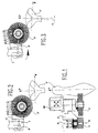
- the carding machine illustrated on the drawings consists of a guide arm 1, onto which an oscillating arm 2 is hinged in A. On the free end of said arm 2 there is finally fixed a carding tool 3, normally a brush with metal bristles, and the respective driving motor M.
- the arm 1 is then connected, in known manner, to control and driving means (not shown) which allow to automatically shift the tool 3 according to a desired working path, along a shoe-tree F which is locked in position under the carding tool 3 and on which there are mounted the bottom and the vamp of a shoe being manufactured.
- a sample shoe-tree When starting to manufacture a new series of shoes of the same type, a sample shoe-tree is first of all locked in position on the shoe manufacturing machine, and a learning operation is carried out on said sample shoe-tree to learn the machining path which the tool 3 will have to perform over the whole series of shoe-trees F of the same type.
- said shoe-trees F - mounted in succession - are locked in position in the carding machine, it easily happens - as already mentioned in the introductory part of the present description - that the angular setting of the shoe-tree F in respect of the longitudinal axis Y of the shoe, once said shoe-tree has been locked in position, is rotated by an angle ⁇ (fig. 3) in respect of the initial position taken up by the sample shoe-tree during the learning step.
- an encoder 4 coaxial to the hinge A, is set between the arm 1 and the arm 2 and is fixedly connected to one of said arms, so as to be apt to detect the respective angular displacements thereof, then transmitting the data concerning such displacements to the above control means.
- the system is thus apt to detect the lateral rotation actually undegone by each single shoe-tree F being manufactured, in respect of the position taken up by the sample shoe-tree, and is apt to accordingly modify the machining path of the carding tool 3 in the subsequent working steps, that is, in particular, in the steps which concern the lateral surface of the vamp.
- this working step can be preceded by a step exclusively meant to detect the lateral rotation of the shoe-tree, by using a device fully similar to that described heretofore in which the carding tool has been replaced by a common feeler.
- This last device can also be of the retractable or foldable type and it can be permanently associated to the carding tool, so that it may be possible to use one or the other, according to uses or preferences, with a simple and practical operation.
Landscapes
- Footwear And Its Accessory, Manufacturing Method And Apparatuses (AREA)
Claims (8)
- Machine de fabrication automatique de chaussure du type comprenant un moyen pour verrouiller l'embauchoir (F) en position, un outil de travail (3) mobile le long dudit embauchoir, et un moyen de commande et d'entraînement pour déplacer ledit outil le long de l'embauchoir suivant un chemin d'usinage prédéterminé sur la base de données mémorisées au préalable dans une zone de stockage dudit moyen de commande, caractérisée en ce que ladite machine de fabrication automatique de chaussure comprend également un système pour détecter et compenser la rotation latérale d'un embauchoir, par rapport à la position de verrouillage initiale d'un embauchoir échantillon, ledit système comprenant un palpeur apte à détecter, après verrouillage de l'embauchoir (F), la rotation latérale dudit embauchoir par rapport à ladite position de verrouillage initiale des embauchoirs échantillons et un moyen de commande apte à modifier le chemin d'usinage de l'outil de travail sur la base des données sur la rotation latérale dudit embauchoir, détectée par ledit palpeur.
- Machine de fabrication automatique de chaussure selon la revendication 1, dans laquelle ledit palpeur est associé audit outil de travail (3) et est apte à détecter la rotation latérale de l'embauchoir (F) pendant l'opération effectuée sur la chaussure par ledit outil.
- Machine de fabrication automatique de chaussure selon la revendication 2, dans laquelle ledit palpeur se compose de l'outil de travail même (3).
- Machine de fabrication automatique de chaussure selon la revendication 3, qui est une machine à carder, et l'opération pendant laquelle la rotation latérale de l'embauchoir (F) est détectée est une opération de cardage sur le fond de la chaussure.
- Machine de fabrication automatique de chaussure selon la revendication 4, dans laquelle l'outil de travail (3) de ladite machine à carder se compose d'une brosse rotative avec des poils métalliques.
- Machine de fabrication automatique de chaussure selon la revendication 4 ou 5, dans laquelle un bras de support (2) dudit outil de cardage (3) s'articule (en A) sur un bras de guidage (1), un encodeur (4) étant positionné en correspondance de ladite articulation (A) et étant apte à détecter les déplacements angulaires entre lesdits bras (1, 2) et à transmettre lesdites informations audit moyen de commande.
- Procédé de fabrication d'une chaussure avec une machine de fabrication automatique de chaussure selon la revendication 6, comprenant un système pour détecter et compenser la rotation latérale d'un embauchoir (F) par rapport à la position de verrouillage initiale d'un embauchoir échantillon, comprenant les étapes suivantes consistant à :a) carder la surface inférieure de la chaussure, etb) détecter la rotation latérale de l'embauchoir par rapport à ladite position de verrouillage initiale de l'embauchoir échantillon ;
étapes effectuées simultanément par ledit outil de cardage (3), et les autres étapes suivantes en série consistant à :c) retraiter, par ledit moyen de commande, les données stockées concernant le chemin d'usinage de l'outil de cardage (3), sur la base des données sur la rotation latérale détectée pendant l'étape b) ;d) effectuer une ou plusieurs opérations successives sur la chaussure sur la base du chemin d'usinage retraité à l'étape c). - Procédé de fabrication d'une chaussure selon la revendication 7, dans lequel les opérations successives effectuées à l'étape d) peuvent être sélectionnées parmi les suivantes : le cardage latéral de la chaussure, l'application d'un adhésif sur la surface cardée inférieure de la chaussure, l'application d'un adhésif sur la surface cardée latérale de la chaussure.
Priority Applications (2)
| Application Number | Priority Date | Filing Date | Title |
|---|---|---|---|
| DE2001617954 DE60117954T2 (de) | 2001-08-16 | 2001-08-16 | Verfahren zur Feststellung und Kompensation der seitlichen Drehung von einem Schuhleisten im Vergleich mit einer vorbestimmten Position in einer automatischen Schuhbearbeitungsvorrichtung |
| EP20010830542 EP1285596B1 (fr) | 2001-08-16 | 2001-08-16 | Système de détection et compensation de la rotation latérale d'une forme de chaussure par rapport à une position de blocage prédéterminée utilisé dans une machine de réalisation de chaussures automatique |
Applications Claiming Priority (1)
| Application Number | Priority Date | Filing Date | Title |
|---|---|---|---|
| EP20010830542 EP1285596B1 (fr) | 2001-08-16 | 2001-08-16 | Système de détection et compensation de la rotation latérale d'une forme de chaussure par rapport à une position de blocage prédéterminée utilisé dans une machine de réalisation de chaussures automatique |
Publications (2)
| Publication Number | Publication Date |
|---|---|
| EP1285596A1 EP1285596A1 (fr) | 2003-02-26 |
| EP1285596B1 true EP1285596B1 (fr) | 2006-03-15 |
Family
ID=8184664
Family Applications (1)
| Application Number | Title | Priority Date | Filing Date |
|---|---|---|---|
| EP20010830542 Expired - Lifetime EP1285596B1 (fr) | 2001-08-16 | 2001-08-16 | Système de détection et compensation de la rotation latérale d'une forme de chaussure par rapport à une position de blocage prédéterminée utilisé dans une machine de réalisation de chaussures automatique |
Country Status (2)
| Country | Link |
|---|---|
| EP (1) | EP1285596B1 (fr) |
| DE (1) | DE60117954T2 (fr) |
Families Citing this family (2)
| Publication number | Priority date | Publication date | Assignee | Title |
|---|---|---|---|---|
| EP1472946A1 (fr) * | 2003-05-02 | 2004-11-03 | Officina Meccanica B.D.F. S.P.A. | Amortisseur à équilibre fluide pour brosse de cardage, dans une machine de cardage de tiges de chaussures |
| WO2017195044A2 (fr) | 2016-02-16 | 2017-11-16 | Eversafe Technologies Limited | Système de couverture portatif sécurisé |
Family Cites Families (3)
| Publication number | Priority date | Publication date | Assignee | Title |
|---|---|---|---|---|
| US4866802A (en) * | 1988-04-08 | 1989-09-19 | International Shoe Machine Corporation | Roughing machine for footware upper assemblies and a system that includes the roughing machine but typically includes as well other machines ahead of and following |
| FR2690864B1 (fr) * | 1992-05-06 | 1996-10-04 | Roger Blanc | Tete pour l'equipement d'un robot, destinee a realiser une operation de cardage. |
| IT230692Y1 (it) * | 1993-10-29 | 1999-06-09 | Mec B D F Srl Off | Macchina automatica di irruvidimento controllato di un bordo di tomaia |
-
2001
- 2001-08-16 DE DE2001617954 patent/DE60117954T2/de not_active Expired - Lifetime
- 2001-08-16 EP EP20010830542 patent/EP1285596B1/fr not_active Expired - Lifetime
Also Published As
| Publication number | Publication date |
|---|---|
| DE60117954T2 (de) | 2006-08-17 |
| EP1285596A1 (fr) | 2003-02-26 |
| DE60117954D1 (de) | 2006-05-11 |
Similar Documents
| Publication | Publication Date | Title |
|---|---|---|
| US4691398A (en) | Shoe making machine | |
| SU1837824A3 (en) | Method and device for molding-on multilayer sole to shoe upper | |
| EP0276944B1 (fr) | Appareil d'application d'adhésif | |
| EP3578070B1 (fr) | Appareil pour la gravure au laser de semelles intérieures et procédé de fonctionnement dudit appareil | |
| EP1285596B1 (fr) | Système de détection et compensation de la rotation latérale d'une forme de chaussure par rapport à une position de blocage prédéterminée utilisé dans une machine de réalisation de chaussures automatique | |
| US4555823A (en) | Machine for the automatic carding of uppers for footwear | |
| NO814120L (no) | Sko med tilformet saale, og fremgangsmaate til fremstilling av samme | |
| US3077098A (en) | Bottom roughing equipment for slip shoes | |
| US4331011A (en) | Automatic roughing machine | |
| US4400839A (en) | Machine for lasting heel seat portions of shoes | |
| JPS58146306A (ja) | 工具の作動通路及び作動部分決定方法、これによる靴製造機、及びこれに用いるグリツド | |
| US2013679A (en) | Shoe part ornamenting machine | |
| EP0091321B1 (fr) | Machine pour le cardage progressif des parties marginales des dessous de chaussures | |
| US1157729A (en) | Lasting-machine. | |
| CA1084660A (fr) | Enclume et methode pour rainurer les semelles de chaussures | |
| US1381917A (en) | Sole-edge-treating tool | |
| US2866988A (en) | Last positioning device for shoe machines | |
| US1163589A (en) | Sole-pressing machine. | |
| KR102058186B1 (ko) | 갑피 절곡 장치 | |
| EP0057516A2 (fr) | Machine pour monter les parties talons de chaussures | |
| US1032881A (en) | Work-support. | |
| GB2091535A (en) | Automatically controlling shoe machinery as a lasted assembly is conveyed therethrough | |
| KR102058207B1 (ko) | 갑피평탄화장치 | |
| US1191832A (en) | Method of making boots and shoes. | |
| US965656A (en) | Adjustable work support and gage for channeling-machines. |
Legal Events
| Date | Code | Title | Description |
|---|---|---|---|
| PUAI | Public reference made under article 153(3) epc to a published international application that has entered the european phase |
Free format text: ORIGINAL CODE: 0009012 |
|
| AK | Designated contracting states |
Kind code of ref document: A1 Designated state(s): AT BE CH CY DE DK ES FI FR GB GR IE IT LI LU MC NL PT SE TR |
|
| AX | Request for extension of the european patent |
Extension state: AL LT LV MK RO SI |
|
| 17P | Request for examination filed |
Effective date: 20030807 |
|
| AKX | Designation fees paid |
Designated state(s): DE GB IT |
|
| 17Q | First examination report despatched |
Effective date: 20050418 |
|
| GRAP | Despatch of communication of intention to grant a patent |
Free format text: ORIGINAL CODE: EPIDOSNIGR1 |
|
| GRAS | Grant fee paid |
Free format text: ORIGINAL CODE: EPIDOSNIGR3 |
|
| GRAA | (expected) grant |
Free format text: ORIGINAL CODE: 0009210 |
|
| AK | Designated contracting states |
Kind code of ref document: B1 Designated state(s): DE GB IT |
|
| REG | Reference to a national code |
Ref country code: GB Ref legal event code: FG4D |
|
| REF | Corresponds to: |
Ref document number: 60117954 Country of ref document: DE Date of ref document: 20060511 Kind code of ref document: P |
|
| PGFP | Annual fee paid to national office [announced via postgrant information from national office to epo] |
Ref country code: GB Payment date: 20060713 Year of fee payment: 6 |
|
| PLBE | No opposition filed within time limit |
Free format text: ORIGINAL CODE: 0009261 |
|
| STAA | Information on the status of an ep patent application or granted ep patent |
Free format text: STATUS: NO OPPOSITION FILED WITHIN TIME LIMIT |
|
| 26N | No opposition filed |
Effective date: 20061218 |
|
| GBPC | Gb: european patent ceased through non-payment of renewal fee |
Effective date: 20070816 |
|
| PG25 | Lapsed in a contracting state [announced via postgrant information from national office to epo] |
Ref country code: GB Free format text: LAPSE BECAUSE OF NON-PAYMENT OF DUE FEES Effective date: 20070816 |
|
| PGFP | Annual fee paid to national office [announced via postgrant information from national office to epo] |
Ref country code: DE Payment date: 20090821 Year of fee payment: 9 |
|
| REG | Reference to a national code |
Ref country code: DE Ref legal event code: R119 Ref document number: 60117954 Country of ref document: DE Effective date: 20110301 |
|
| PG25 | Lapsed in a contracting state [announced via postgrant information from national office to epo] |
Ref country code: DE Free format text: LAPSE BECAUSE OF NON-PAYMENT OF DUE FEES Effective date: 20110301 |
|
| PGFP | Annual fee paid to national office [announced via postgrant information from national office to epo] |
Ref country code: IT Payment date: 20120719 Year of fee payment: 12 |
|
| PG25 | Lapsed in a contracting state [announced via postgrant information from national office to epo] |
Ref country code: IT Free format text: LAPSE BECAUSE OF NON-PAYMENT OF DUE FEES Effective date: 20130816 |