EP1285645A2 - Elévateur de bain pour personnes âgées et handicapés - Google Patents
Elévateur de bain pour personnes âgées et handicapés Download PDFInfo
- Publication number
- EP1285645A2 EP1285645A2 EP02017331A EP02017331A EP1285645A2 EP 1285645 A2 EP1285645 A2 EP 1285645A2 EP 02017331 A EP02017331 A EP 02017331A EP 02017331 A EP02017331 A EP 02017331A EP 1285645 A2 EP1285645 A2 EP 1285645A2
- Authority
- EP
- European Patent Office
- Prior art keywords
- spindle
- seat plate
- lifting device
- gear
- lifting
- Prior art date
- Legal status (The legal status is an assumption and is not a legal conclusion. Google has not performed a legal analysis and makes no representation as to the accuracy of the status listed.)
- Granted
Links
Images


Classifications
-
- A—HUMAN NECESSITIES
- A61—MEDICAL OR VETERINARY SCIENCE; HYGIENE
- A61G—TRANSPORT, PERSONAL CONVEYANCES, OR ACCOMMODATION SPECIALLY ADAPTED FOR PATIENTS OR DISABLED PERSONS; OPERATING TABLES OR CHAIRS; CHAIRS FOR DENTISTRY; FUNERAL DEVICES
- A61G7/00—Beds specially adapted for nursing; Devices for lifting patients or disabled persons
- A61G7/10—Devices for lifting patients or disabled persons, e.g. special adaptations of hoists thereto
- A61G7/1001—Devices for lifting patients or disabled persons, e.g. special adaptations of hoists thereto specially adapted for specific applications
- A61G7/1003—Devices for lifting patients or disabled persons, e.g. special adaptations of hoists thereto specially adapted for specific applications mounted on or in combination with a bath-tub
-
- A—HUMAN NECESSITIES
- A61—MEDICAL OR VETERINARY SCIENCE; HYGIENE
- A61G—TRANSPORT, PERSONAL CONVEYANCES, OR ACCOMMODATION SPECIALLY ADAPTED FOR PATIENTS OR DISABLED PERSONS; OPERATING TABLES OR CHAIRS; CHAIRS FOR DENTISTRY; FUNERAL DEVICES
- A61G7/00—Beds specially adapted for nursing; Devices for lifting patients or disabled persons
- A61G7/10—Devices for lifting patients or disabled persons, e.g. special adaptations of hoists thereto
- A61G7/1013—Lifting of patients by
- A61G7/1019—Vertical extending columns or mechanisms
-
- A—HUMAN NECESSITIES
- A61—MEDICAL OR VETERINARY SCIENCE; HYGIENE
- A61G—TRANSPORT, PERSONAL CONVEYANCES, OR ACCOMMODATION SPECIALLY ADAPTED FOR PATIENTS OR DISABLED PERSONS; OPERATING TABLES OR CHAIRS; CHAIRS FOR DENTISTRY; FUNERAL DEVICES
- A61G7/00—Beds specially adapted for nursing; Devices for lifting patients or disabled persons
- A61G7/10—Devices for lifting patients or disabled persons, e.g. special adaptations of hoists thereto
- A61G7/1049—Attachment, suspending or supporting means for patients
- A61G7/1059—Seats
Definitions
- the invention relates to a bath tub lifter for the elderly and the disabled, comprising lifting scissors through which a seat plate relative to one Floor frame is adjustable in height, a backrest connected to the seat plate, a telescopic lifting device, on the one hand with the Backrest and connected to the seat plate and on the other hand on the Base frame is supported, and a drive device for driving the lifting device.
- Bath tub lifters of this type are generally operated using a hand control controlled, the one button for moving up and moving down the seat plate includes. Furthermore, these bath tub lifters an emergency stop switch is also provided, which allows movement of the seat plate immediately interrupts.
- a disadvantage of this known solution is that the seat plate their downward movement does not automatically occur when a Body part of a bathing person interrupts.
- Another protective device provides a torque transmitted via a wrap spring that is not between two with each other connected cylinders sits. When the drive shaft rotates this spring closes and transmits the torque as it moves opens in the opposite direction of rotation and therefore no torque transfers.
- This embodiment also requires an extremely large amount of space required.
- a limit switch via an integrated microswitch which is used for a force resulting from pinching a part of a person's body is actuated and the power supply to the drive motor is interrupted, is also used in these applications.
- An object of the invention is to provide a known bathtub lifter train that the downward movement of the seat plate by one acting on the lifting device, from pinching one Part of the body of a bathing person resulting in reliable operation, is stopped quickly and independently. Furthermore, it is provided that Bathtub lifter of the type mentioned in such a way that costly electrical circuits can be dispensed with and a particularly small space requirement is required.
- the lifting device comprises an output gear, which with a with the drive device connected drive wheel forms a gear and can be brought into engagement, the two gear wheels acting on the lifting device, from pinching a body part of a bathing person resulting tensile force are separable.
- This configuration enables a particularly space-saving and functionally reliable Clamp protection device to implement that are not sensitive Includes electronic components.
- the invention further advantageously provides that the transmission as Gear transmission and in particular as a bevel gear, wherein the driven wheel engages with the drive wheel by means of a compression spring is feasible.
- the gear wheels transmit the rotary movements from one to the other Drive shaft of the drive device on an output shaft of the lifting device, which causes a height adjustment of the seat plate.
- the gears are separable if resulting from pinching a body part of a bathing person Tensile force is greater than that counteracted by the compression spring Compressive force. Controls and other electrical circuits are thus not necessary as this protection against jamming is only mechanical Components includes.
- the lifting device is preferably designed as a screw drive and comprises a spindle outer tube in which a lifting spindle with a spindle nut is provided, with the spindle nut a spindle inner tube is connected to a spindle foot.
- the seat plate is moved in a straight line, the use of a Screw drive particularly advantageous.
- the one associated with the spindle nut Spindle inner tube is in a spindle foot receptacle of the base frame supported. Rotation of the spindle causes an axial movement the spindle nut and thus a height adjustment of the seat plate.
- the compression spring is arranged in a fixed position in the spindle outer tube If the sleeve is supported, the driven wheel normally engages in the drive wheel on. The end of the compression spring facing the spindle nut is through this Sleeve set in position.
- the spindle foot in the spindle foot receptacle Bottom frame is fixed axially movable, with a contact plate with a Recess for the spindle foot covers the spindle foot receptacle.
- the Spindle base includes an annular shoulder, which at one from pinching of a body part of a bathing person resulting in axial movement rests on the contact plate.
- a bath tub lifter is shown in its entirety. It includes a base frame 1 with feet 51, the bottom of a, not shown Bathtub is laid.
- the bathtub lifter also includes a seat plate 2, which is relative to the base frame 1 by lifting scissors 3 is adjustable in height.
- On the seat plate 2 is a swiveling backrest 4 articulated via a swivel joint 5.
- Lifting device 52 with its upper end 8 in a storage device 9 is mounted on the back of the backrest 4, and with its lower End 10 is supported in the base frame 1.
- the lifting scissors arranged between the base frame 1 and the seat plate 2 3 includes a scissor cross on each side of the base frame 1 and the seat plate 2.
- a construction with two would be Swivel arms possible.
- Each scissor cross is by two in the middle struts 12, 13 connected to one another by a swivel joint 11 formed, the upper free end 14 of the strut 12 on a pivot bearing 15 of the seat plate 2 and the lower end 16 of the strut 13 on one Pivot bearings 17 of the base frame 1 are mounted.
- the free end 18 of the Strut 13 and the free end 19 of the strut 12 are in slide shoes Guide rails 20 of the seat plate 2 or 21 of the base frame 1 sliding stored.
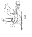
- the lifting device 52 comprises a lifting spindle 7, which has a longitudinal axis 22 and has a trapezoidal thread 23.
- the lifting spindle 7 carries a spindle nut 24 with a trapezoidal internal thread that fits into a spindle inner tube 25 protrudes and is firmly connected to it.
- the spindle inner tube 25 surrounds the lifting spindle 7 and one in the spindle inner tube 25 protruding fixing section 26 of the spindle nut 24.
- the spindle inner tube 25 forms the lower end 10 of the lifting device 52 and points a spindle foot 27, which is in a spindle foot receptacle 28 of the base frame 1 is supported.
- the lifting device 52 also has a spindle outer tube 29, that surrounds both the spindle nut 24 and the spindle inner ear 25, the spindle nut 24 with a ring portion 30 on the inside of the spindle outer tube 29 abuts by a rotational relative movement to effect between the lifting spindle 7 and the spindle nut 24.
- the lifting spindle has at the end opposite the spindle foot 27 7 shows a spindle pin 31 which is tapered in cross section.
- a driven gear 32 is connected in a rotationally fixed manner
- Drive wheel 33 of the drive device 6 is engaged.
- the drive wheel 33 is rotationally fixed by a drive shaft 34 of the drive device 6 worn, the drive shaft 34 having a longitudinal axis 35 which runs perpendicular to the longitudinal axis 22 of the lifting spindle 7.
- the drive wheel 33 and the driven gear 32 together form a bevel gear 50 Diameters of the gear wheels 32, 33 are identical.
- a receiving sleeve 36 by one on the front side of the spindle outer tube 29 adjacent ring projection 37 in their position is set.
- the end of the receiving sleeve opposite the annular projection 37 36 is provided with an annular bottom section 38, which axially fixes a helical compression spring 39.
- the other end of the Compression spring 39 is in a receiving gap 40 of a further receiving sleeve 41 is added, which is adjacent to a bearing on the driven wheel 32
- Rolling bearing 42 is mounted.
- the two receiving sleeves 36, 41 are spaced apart.
- the roller bearing 42 is through that Output gear 32 and by a slid onto the spindle pin 31 Fixing disc 43 fixed in position, the fixing disc 43 at the transition from the spindle pin 31 to the lifting spindle 7 is present.
- the force generated by the lifting device 52 is generated by a clamping ring 44 applied to the seat plate 2 to be adjusted, the one with the spindle outer tube 29 is positively connected.
- On the seat plate 2 is the Clamping ring 44 pivoted.
- the spindle foot 27 has a conical shape Cross section on.
- the spindle foot 27 is supported with its tip on a base 45 of the spindle foot receptacle 28, which in the base frame 1 is formed.
- the spindle foot receptacle 28 comprises a contact plate 46 with a recess 47 for the spindle foot 27.
- the contact plate 46 is arranged at a distance from the base 45 and covers the spindle foot receptacle 28 from.
- the spindle foot 27 has an annular shoulder 48, whose diameter is larger than the diameter of the recess 47.
- the Drive shaft 34 is powered by the preferably battery powered drive device 6 driven.
- the drive wheel connected to the drive shaft 34 33 is thus also driven and transmits this through the Drive device 6 applied torque to the driven wheel 32, which is arranged in a rotationally fixed manner on the spindle pin 31, as a result of which the lifting spindle 7 is rotated.
- the spindle pin 31 and the lifting spindle 7 are to be regarded as an output shaft. The rotation of the lifting spindle 7 causes an axial movement of the spindle nut 24.
Landscapes
- Health & Medical Sciences (AREA)
- Nursing (AREA)
- Life Sciences & Earth Sciences (AREA)
- Animal Behavior & Ethology (AREA)
- General Health & Medical Sciences (AREA)
- Public Health (AREA)
- Veterinary Medicine (AREA)
- Devices For Medical Bathing And Washing (AREA)
- Bathtubs, Showers, And Their Attachments (AREA)
Applications Claiming Priority (2)
| Application Number | Priority Date | Filing Date | Title |
|---|---|---|---|
| DE2001140847 DE10140847A1 (de) | 2001-08-21 | 2001-08-21 | Badewannenlifter für Senioren und Behinderte |
| DE10140847 | 2001-08-21 |
Publications (3)
| Publication Number | Publication Date |
|---|---|
| EP1285645A2 true EP1285645A2 (fr) | 2003-02-26 |
| EP1285645A3 EP1285645A3 (fr) | 2004-01-28 |
| EP1285645B1 EP1285645B1 (fr) | 2005-12-28 |
Family
ID=7696064
Family Applications (1)
| Application Number | Title | Priority Date | Filing Date |
|---|---|---|---|
| EP20020017331 Expired - Lifetime EP1285645B1 (fr) | 2001-08-21 | 2002-08-02 | Elévateur de bain pour personnes âgées et handicapées |
Country Status (3)
| Country | Link |
|---|---|
| EP (1) | EP1285645B1 (fr) |
| CA (1) | CA2397503C (fr) |
| DE (2) | DE10140847A1 (fr) |
Families Citing this family (5)
| Publication number | Priority date | Publication date | Assignee | Title |
|---|---|---|---|---|
| EP2359793A1 (fr) | 2010-02-11 | 2011-08-24 | Invacare International Sàrl | Dispositif pour soulever une baignoire |
| EP3130322B1 (fr) | 2015-08-11 | 2018-05-23 | Invacare International Sàrl | Dispositif de levage pour baignoire |
| US11654066B2 (en) | 2019-06-13 | 2023-05-23 | Drive Medical Gmbh & Co. Kg | Bathtub lift |
| DE102019116171B3 (de) | 2019-06-13 | 2020-09-03 | Drive Medical Gmbh & Co. Kg | Badewannenlifter |
| CN222738148U (zh) * | 2024-05-23 | 2025-04-11 | 士商(上海)机械有限公司 | 一种塑料电动辅助起重设备 |
Family Cites Families (7)
| Publication number | Priority date | Publication date | Assignee | Title |
|---|---|---|---|---|
| GB2234491B (en) * | 1989-08-05 | 1993-07-07 | John Alfred Hooker | Electrically powered bath aid unit |
| DE9300438U1 (de) * | 1993-01-15 | 1993-03-11 | Dewert Antriebs- und Systemtechnik GmbH & Co. KG, 4983 Kirchlengern | Hubeinrichtung |
| DE4437513C2 (de) * | 1994-10-20 | 1997-07-17 | Walter Gobbers | Vorrichtung zum Einsetzen in eine Badewanne oder dergleichen als Ein- und Ausstiegshilfe |
| DE19532595C1 (de) * | 1995-09-04 | 1996-08-08 | Robert Forwick | Schwenkvorrichtung für eine Badehilfe |
| DE19701591A1 (de) * | 1997-01-18 | 1998-07-23 | Aquatec Peter Schmidt Gmbh | Badelift für Senioren und Behinderte |
| DE19833384A1 (de) * | 1998-07-24 | 2000-01-27 | Aquatec Peter Schmidt Gmbh | Badewannenlifter |
| DE20100096U1 (de) * | 2001-01-04 | 2001-06-21 | Gobbers, Walter, 89518 Heidenheim | Badelift |
-
2001
- 2001-08-21 DE DE2001140847 patent/DE10140847A1/de not_active Withdrawn
-
2002
- 2002-08-02 DE DE50205409T patent/DE50205409D1/de not_active Expired - Lifetime
- 2002-08-02 EP EP20020017331 patent/EP1285645B1/fr not_active Expired - Lifetime
- 2002-08-12 CA CA 2397503 patent/CA2397503C/fr not_active Expired - Fee Related
Also Published As
| Publication number | Publication date |
|---|---|
| DE50205409D1 (de) | 2006-02-02 |
| CA2397503A1 (fr) | 2003-02-21 |
| EP1285645A3 (fr) | 2004-01-28 |
| DE10140847A1 (de) | 2003-03-06 |
| CA2397503C (fr) | 2010-10-05 |
| EP1285645B1 (fr) | 2005-12-28 |
Similar Documents
| Publication | Publication Date | Title |
|---|---|---|
| EP0048294B1 (fr) | Ferrure d'articulation, en particulier pour sièges à dossier réglable | |
| DE102014001984B4 (de) | Verstelleinrichtung für Fahrzeugsitze | |
| EP1162933A1 (fr) | Lit pour malade et/ou d'infirmerie et element support reglable en longueur pour ce lit | |
| DE2808954A1 (de) | Gelenkbeschlag fuer sitze mit verstellbarer rueckenlehne, insbesondere kraftfahrzeugsitze | |
| DE19818821A1 (de) | Hubvorrichtung zum Heben einer Last, insbesondere zum Heben eines Rollstuhls | |
| EP0707843A1 (fr) | Dispositif pour monter dans une baignoire ou analogue comme aide d'entrer ou de sortir | |
| EP0146914B1 (fr) | Commande électromotrice pour le réglage du support de tête ou de jambes d'un meuble de couchage | |
| EP0789986B1 (fr) | Bielle de relevage pour accouplement à trois points de tracteur | |
| EP1285645B1 (fr) | Elévateur de bain pour personnes âgées et handicapées | |
| DE29818691U1 (de) | Linearantrieb | |
| WO2005082311A1 (fr) | Chariot de massage | |
| DE4137466A1 (de) | Laengenveraenderliche kruecke | |
| DE3129101A1 (de) | Laengenveraenderbare vorrichtung zum verstellen der position eines fahrzeugsitzes | |
| EP3806802B1 (fr) | Système de transport | |
| EP3752027B1 (fr) | Meuble d'assise et de support | |
| EP0478584B1 (fr) | Accessoire pour aider a entrer dans une baignoire | |
| DE19960932A1 (de) | Linearantrieb | |
| DE4437515A1 (de) | Vorrichtung zum Einsetzen in eine Badewanne oder dergleichen als Ein- und Ausstiegshilfe | |
| DE102016108270A1 (de) | Medizinische Haltearmvorrichtung | |
| WO1992014377A1 (fr) | Parasol | |
| EP0870475A1 (fr) | Chaise pour médecins | |
| DE2939799C2 (de) | Kombinierte Brems- und Antriebseinheit | |
| EP0593791B1 (fr) | Dispositif pour déplacer un appareil dentaire | |
| DE10233106C1 (de) | Badewannenlifter | |
| EP3453372A1 (fr) | Système de levage à barres croisées pour élévateur de bain |
Legal Events
| Date | Code | Title | Description |
|---|---|---|---|
| PUAI | Public reference made under article 153(3) epc to a published international application that has entered the european phase |
Free format text: ORIGINAL CODE: 0009012 |
|
| AK | Designated contracting states |
Kind code of ref document: A2 Designated state(s): AT BE BG CH CY CZ DE DK EE ES FI FR GB GR IE IT LI LU MC NL PT SE SK TR |
|
| AX | Request for extension of the european patent |
Extension state: AL LT LV MK RO SI |
|
| PUAL | Search report despatched |
Free format text: ORIGINAL CODE: 0009013 |
|
| AK | Designated contracting states |
Kind code of ref document: A3 Designated state(s): AT BE BG CH CY CZ DE DK EE ES FI FR GB GR IE IT LI LU MC NL PT SE SK TR |
|
| AX | Request for extension of the european patent |
Extension state: AL LT LV MK RO SI |
|
| 17P | Request for examination filed |
Effective date: 20040319 |
|
| AKX | Designation fees paid |
Designated state(s): DE GB |
|
| GRAP | Despatch of communication of intention to grant a patent |
Free format text: ORIGINAL CODE: EPIDOSNIGR1 |
|
| GRAS | Grant fee paid |
Free format text: ORIGINAL CODE: EPIDOSNIGR3 |
|
| GRAA | (expected) grant |
Free format text: ORIGINAL CODE: 0009210 |
|
| AK | Designated contracting states |
Kind code of ref document: B1 Designated state(s): DE GB |
|
| REG | Reference to a national code |
Ref country code: GB Ref legal event code: FG4D Free format text: NOT ENGLISH |
|
| GBT | Gb: translation of ep patent filed (gb section 77(6)(a)/1977) |
Effective date: 20051229 |
|
| REF | Corresponds to: |
Ref document number: 50205409 Country of ref document: DE Date of ref document: 20060202 Kind code of ref document: P |
|
| PLBE | No opposition filed within time limit |
Free format text: ORIGINAL CODE: 0009261 |
|
| STAA | Information on the status of an ep patent application or granted ep patent |
Free format text: STATUS: NO OPPOSITION FILED WITHIN TIME LIMIT |
|
| 26N | No opposition filed |
Effective date: 20060929 |
|
| REG | Reference to a national code |
Ref country code: DE Ref legal event code: R082 Ref document number: 50205409 Country of ref document: DE Representative=s name: STAUDT IP LAW, DE |
|
| PGFP | Annual fee paid to national office [announced via postgrant information from national office to epo] |
Ref country code: DE Payment date: 20160816 Year of fee payment: 15 Ref country code: GB Payment date: 20160824 Year of fee payment: 15 |
|
| REG | Reference to a national code |
Ref country code: DE Ref legal event code: R119 Ref document number: 50205409 Country of ref document: DE |
|
| GBPC | Gb: european patent ceased through non-payment of renewal fee |
Effective date: 20170802 |
|
| PG25 | Lapsed in a contracting state [announced via postgrant information from national office to epo] |
Ref country code: DE Free format text: LAPSE BECAUSE OF NON-PAYMENT OF DUE FEES Effective date: 20180301 Ref country code: GB Free format text: LAPSE BECAUSE OF NON-PAYMENT OF DUE FEES Effective date: 20170802 |