EP1285678A2 - Einzel-Elektrodensonde für Herzschrittmachersysteme - Google Patents
Einzel-Elektrodensonde für Herzschrittmachersysteme Download PDFInfo
- Publication number
- EP1285678A2 EP1285678A2 EP02090297A EP02090297A EP1285678A2 EP 1285678 A2 EP1285678 A2 EP 1285678A2 EP 02090297 A EP02090297 A EP 02090297A EP 02090297 A EP02090297 A EP 02090297A EP 1285678 A2 EP1285678 A2 EP 1285678A2
- Authority
- EP
- European Patent Office
- Prior art keywords
- electrode
- electrode line
- strands
- section
- part section
- Prior art date
- Legal status (The legal status is an assumption and is not a legal conclusion. Google has not performed a legal analysis and makes no representation as to the accuracy of the status listed.)
- Granted
Links
- 239000000523 sample Substances 0.000 claims abstract description 34
- 210000004165 myocardium Anatomy 0.000 claims abstract description 16
- 230000000747 cardiac effect Effects 0.000 claims abstract 4
- 210000002837 heart atrium Anatomy 0.000 claims description 21
- 229910052751 metal Inorganic materials 0.000 claims description 19
- 239000002184 metal Substances 0.000 claims description 19
- 230000001746 atrial effect Effects 0.000 claims description 16
- 210000002435 tendon Anatomy 0.000 claims description 15
- 239000013013 elastic material Substances 0.000 claims description 3
- 230000007704 transition Effects 0.000 claims description 2
- 238000004804 winding Methods 0.000 claims 1
- 230000002861 ventricular Effects 0.000 description 7
- 230000000638 stimulation Effects 0.000 description 6
- 238000002513 implantation Methods 0.000 description 4
- 238000002788 crimping Methods 0.000 description 3
- 238000007667 floating Methods 0.000 description 3
- 239000000463 material Substances 0.000 description 3
- 210000004204 blood vessel Anatomy 0.000 description 2
- 230000036760 body temperature Effects 0.000 description 2
- 230000009977 dual effect Effects 0.000 description 2
- 238000010438 heat treatment Methods 0.000 description 2
- 238000003780 insertion Methods 0.000 description 2
- 230000037431 insertion Effects 0.000 description 2
- 230000001960 triggered effect Effects 0.000 description 2
- 229910001069 Ti alloy Inorganic materials 0.000 description 1
- 238000004873 anchoring Methods 0.000 description 1
- 210000001992 atrioventricular node Anatomy 0.000 description 1
- 239000002826 coolant Substances 0.000 description 1
- 238000005265 energy consumption Methods 0.000 description 1
- 238000005516 engineering process Methods 0.000 description 1
- 230000006870 function Effects 0.000 description 1
- 230000014759 maintenance of location Effects 0.000 description 1
- 238000000034 method Methods 0.000 description 1
- 230000001575 pathological effect Effects 0.000 description 1
- 230000001830 phrenic effect Effects 0.000 description 1
- 230000008569 process Effects 0.000 description 1
- 210000001013 sinoatrial node Anatomy 0.000 description 1
- 238000002560 therapeutic procedure Methods 0.000 description 1
Images
Classifications
-
- A—HUMAN NECESSITIES
- A61—MEDICAL OR VETERINARY SCIENCE; HYGIENE
- A61N—ELECTROTHERAPY; MAGNETOTHERAPY; RADIATION THERAPY; ULTRASOUND THERAPY
- A61N1/00—Electrotherapy; Circuits therefor
- A61N1/02—Details
- A61N1/04—Electrodes
- A61N1/05—Electrodes for implantation or insertion into the body, e.g. heart electrode
- A61N1/056—Transvascular endocardial electrode systems
Definitions
- the invention relates to a single electrode probe for pacemaker systems, especially for DDD pacemaker systems with an electrode lead, which has a two-part section, at the beginning an electrode line strand is divided into two strands, which are on Join the end of the section back into a strand, at least one of the strands has at least one electrode for delivering electrical energy adjacent myocardium.
- DDD pacemaker systems are already available known.
- pacing Dual pacing / dual sensing / demand + triggered
- sensing existing own actions of the sinus or AV node of the heart are sensed in both the atrium and the ventricle.
- double lead DDD pacemaker systems are already available known.
- their main drawbacks are that two separate electrode probes are implanted in the heart and positioned there Need to become.
- Single probes are also known in which a ventricular electrode at the tip of the probe and two atrial ring electrodes in the corresponding Distance from the ventricular electrode are arranged on the probe body.
- the atrial ring electrodes are used to measure the atrial potential detect what causes ventricular pacing after an appropriate atrioventricular Delay is triggered. Ventricular pacing can done bipolar. In principle, it is conceivable to use the one discussed above Single electrode probe can also be used for DDD pacemaker systems.
- the atrial ring electrodes do not are placed on the wall, but float freely in the bloodstream. These so-called "Floating" electrodes in the atrium lead to considerable restrictions the stimulation properties, since mostly very high stimulation amplitudes must be used. The main reason for this is the lack Wall integrity of the floating electrodes. The high stimulation amplitudes bring the disadvantage of high energy consumption and more often Phrenic stimulation with itself.
- EP 0 779 079 discloses a single electrode probe (single lead), the part length of the implanted state in the atrium is given such a shape that at least one atrial electrode - usually a ring electrode - the probe on the atrial wall of the heart is wall-mounted.
- the probe is on the provided partial length with an elastic preform element, which gives the probe a defined deflected shape there.
- the preform element can be elastic from its defined shape converted to a substantially rectilinear stretched condition be what using the usual, used in probe implantation Guidewire is done.
- the guidewire must have elasticity properties of course, be significantly stiffer than the preform element.
- the probe is actually implanted the guide wire is pushed all the way to the tip of the probe, with this feed of the guide wire a tensile force on the probe body is exercised, which leads to a stretching of the probe in the area of the Preform element leads. In this stretched state, the probe can then be introduced into the heart. After implanting the probe and pulling out the guide wire, the probe is then on said Partial length designed by the preform element so that the probe with at least one atrial ring electrode on the atrial wall of the heart is applied.
- a disadvantage here is the relatively complicated design this single electrode probe. Further use of a guidewire not desirable when implanting the single electrode probe.
- EP 0 426 089 describes an electrode arrangement with two separate electrode probes known, one of the electrode probes in the atrium and is inserted further into the ventricle, while the other electrode probe than Counter electrode on the outside of the heart, i. H. as an endocardial counter electrode, is attached.
- a helix electrode 25 provided as a tip electrode in the right ventricular Myocardium is attached by screwing it in there.
- Above the Tip electrode is a section of the line in two parts, wherein both strands of the divided section each have a spiral electrode 22, 24 for defibrillation.
- the two branches are against each other biased so that they are spaced apart when implanted are arranged.
- the electrodes 22, 24 are intended to make contact with the right ventricular myocardium.
- the disadvantage here, however, is that two separate electrode probes need to be implanted.
- the electrode line is only in the Ventricle adequately attached so that the electrodes are in the atrium are designed as floating electrodes.
- An electrical contact the syringe electrode in the ventricle can be easily secured while the electrical contacts in the atrium can be critical and thus has the disadvantages described above.
- Also for attachment of electrodes in the atrium are different from those for Attach electrodes in the ventricle, since it is essentially the atrium is a "passage".
- FIG. 4f of US Pat. No. 4,154,247 also shows an electrode line a branched section 620 that is shown for placement is provided in the ventricle, but also in the atrium as described of the heart.
- US 4,154,247 says nothing Fixation of the electrode lead.
- the object of the invention is to be fixed in the atrium of a heart Specify electrode lead.
- this object is achieved by a single electrode probe solved the type mentioned, in which the two-part section on the Electrode line is arranged and configured, the electrode line in the implanted state to provide support in the atrium of a heart.
- Such a two-part section of the electrode line contributes significantly Improve the retention of electrodes on the atrial myocardium without doing so to complicate the design of the electrode line significantly.
- the two run Strands of the two-part section of the electrode line parallel to each other and are pre-shaped so that they curve convexly outwards, around diametrically opposite together with the ring electrodes in the implanted state to be pressed against the atrial myocardium.
- only one of the two Strands of the two-part section at least one ring electrode intended.
- Another embodiment variant consists in an electrode line, the one stiffening coil made of elastic material, which in a variety is formed by turns.
- a tendon In the lumen of this electrode line is a tendon is provided, which has its distal end on the electrode lead is attached. By pulling on the tendon this results in a compressive force in the electrode lead.
- the helix is designed that the electrode lead pulls on the tendon from its longitudinal direction bends and takes a predetermined three-dimensional shape. When using appropriate materials, this shape can be fixed so that the Electrode lead maintains the three-dimensional deformation when the train over the tendon.
- Such an embodiment of the electrode line can alternatively or additionally to the aforementioned preforming of the electrode line be provided.
- Another embodiment is characterized by a memory metal element in the area of the electrode line to be deformed, which, for example has a titanium alloy known per se, which if exceeded a trigger temperature their shape from a first to a second shape changed.
- This memory metal element is designed to be its first Form corresponds to a substantially elongated electrode line that a easy insertion of the electrode lead allowed while the second form of the memory metal after exceeding the trigger temperature to an inventive deformed electrode lead.
- a heating element for heating the memory metal element to the trigger temperature be provided if the body temperature is not sufficient, to reach the trigger temperature.
- coolants can be provided, alternatively the electrode lines are also inserted in the cooled state, so that it is slow during and after insertion into the blood vessel warmed and finally reached the trigger temperature.
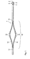
- FIG. 1 shows that section of a single lead electrode line 1 which to be placed in a heart.
- a distal end 2 of the electrode lead 1 and the immediately adjacent section of the electrode line 1 are intended for placement in a ventricle of a heart.
- the electrode line 1 has a tip electrode 3, one in ring electrode 4 located near the tip electrode and so-called Tines 5 for anchoring the lead in the myocardium of the ventricle.
- a heart On the distal section of the electrode lead intended for placement in the ventricle 1 is followed by a section 10 for placement in the atrium a heart is provided.
- the electrode line 1 divided into two strands 11 and 12.
- the two strands 11 and 12 unite at a proximal end 13 of the two-part section 10 to a single electrode line, for example to one implantable pacemaker leads.
- At the distal end 14 of the two-part Section 10 combines the two strands 11 and 12 to form that distal Section of the electrode line 1, which is for the arrangement in the ventricle is trained.
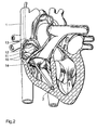
- the two strands 11 and 12 each carry two ring electrodes 15, the Stimulation of the myocardium in the area of the atrium.
- the two strands 11 and 12 are biased against each other in such a way that in the implanted state, in particular in the area of the electrodes 15 diametrically opposed walls of the atrium are pressed, as shown in Figure 2.
- the two strands 11 and 12 of the electrode line 1 are in the implanted state - apart from the transition areas at 13 and 14 - convex outwards to make a good one ensure electrical contact of the ring electrodes 15 to the atrial myocardium and at the same time the electrode line 1 in the atrium only through the Fix preforming.
- the good holding function of the two-part section of the electrode line on the atrial myocardium and therefore good electrical contact the two strands 11 and 12 located ring electrodes 15 with the atrial Myocardium is realized by the outwardly curved strands 11 and 12, which at the diametrically opposite points in the atrium Are clamped due to their mutual bias.
- the elasticity properties the strands 11 and 12 are chosen in such a way that ensures is that the electrical contact of the electrodes 15 with the atrial Myocardium is guaranteed permanently.
- the two-part section can also be designed such that only one one or more electrodes 15 of the two strands 11 and 12 are provided become.
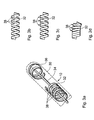
- FIGS. 3a to d show an embodiment variant in a detailed representation the electrode lead, which is stretched into the atrium of the heart can be introduced and after its introduction according to the invention Can take shape.
- the electrode line section 10 in FIG. 3 comprises a sheath 30 (in FIG 3a only indicated) as well as a metal coil 32 and within the shell 30 one arranged in a lumen enclosed by the metal coil 32 Tendon 34 at its distal end via a connecting plate 36 the metal coil 32 is connected.
- FIG. 3b shows a section of the metal coil 32 in a top view
- the 3c shows the section of the metal helix 32 in a side view.
- the individual turns of the metal coil 32 from each other are spaced apart and that the strip material from which the metal coil 32 exists, is made wider at points 38.
- By train on the Tendon 34 shortens the metal helix 32 to the turns of the metal helix 32 abut each other; see figure 3d. Since the tape material of the Metal helix 32 is widened at points 38, keeps the shortened or compressed metal helix 32 not its elongated shape, but assumes the bend shown in Figure 3d.
- the coils can correspond to the metal coils 32 be designed so that an electrode line is introduced by pulling on an Tendon takes any three-dimensional curvature. Without train on the tendon the electrode lead is stretched and flexible and can easily inserted into the blood vessel, as indicated in Figure 3a.
- a single electrode probe like the one shown typically has one (not shown here) electrode plug at its proximal end in order the electrode lead with a therapy device such as a pacemaker connect to.
- a therapy device such as a pacemaker connect to.
- the electrode plug preferably has a clamp or crimping device. The tendon becomes accordingly tightened or tightened after implantation of the electrode lead and in tightened state fixed in the area of the electrode connector.
Landscapes
- Health & Medical Sciences (AREA)
- Heart & Thoracic Surgery (AREA)
- Vascular Medicine (AREA)
- Cardiology (AREA)
- Engineering & Computer Science (AREA)
- Biomedical Technology (AREA)
- Nuclear Medicine, Radiotherapy & Molecular Imaging (AREA)
- Radiology & Medical Imaging (AREA)
- Life Sciences & Earth Sciences (AREA)
- Animal Behavior & Ethology (AREA)
- General Health & Medical Sciences (AREA)
- Public Health (AREA)
- Veterinary Medicine (AREA)
- Electrotherapy Devices (AREA)
- Measurement And Recording Of Electrical Phenomena And Electrical Characteristics Of The Living Body (AREA)
Abstract
Description
- Figur 1
- ein zum Platzieren im Herzen vorgesehenes distales Ende einer Elektrodenleitung;
- Figur 2
- der in Figur 1 abgebildete Abschnitt der Elektrodenleitung platziert in einem Herzen.
- Figuren 3a bis d
- ein Ausführungsdetail einer Elektrodenleitung die durch Stauchen einer versteifenden Wendel verformbar ist;
Claims (6)
- Einzel-Elektrodensonde für Herzschrittmachersysteme, insbesondere für DDD- Herzschrittmachersysteme, mit einer Elektrodenleitung (1), welche einen zweigeteilten Abschnitt (10) aufweist, an dessen Beginn (13) sich ein Elektrodenleitungsstrang in zwei Stränge (11, 12) aufteilt, welche sich am Ende (14) des Abschnittes (10) wieder zu einem Strang vereinen, von denen wenigstens einer der Stränge (11, 12) mindestens eine Elektrode (15) zur Abgabe elektrischer Energie an angrenzendes Myokard trägt, dadurch gekennzeichnet, dass der zweigeteilte Abschnitt auf der Elektrodenleitung (1) angeordnet und gestaltet ist, der Elektrodenleitung im implantierten Zustand Halt im Atrium eines Herzens zu verschaffen.
- Einzel-Elektrodensonde nach Anspruch 1, bei der jeweils zwei Ringelektroden (15) an den jeweiligen Strängen (11, 12) des zweigeteilten Abschnittes der Elektrodenleitung (1) angeordnet sind.
- Einzel-Elektrodensonde nach Anspruch 1, bei der die beiden Stränge (11, 12) des zweigeteilten Abschnitts (10) der Elektrodenleitung (1) parallel zu einander verlaufen und derart vorgeformt sind, dass sie sich im implantierten Zustand konvex nach außen wölben, um im implantierten Zustand diametral gegenüberliegend mitsamt der Ringelektroden (15) gegen das atriale Myokard gedrückt zu werden.
- Einzel-Elektrodensonde nach Anspruch 1, bei der nur an einem der beiden Stränge (11, 12) des zweigeteilten Abschnitts (10) zumindest eine Ringelektrode (15) vorgesehen ist.
- Elektrodenleitung für eine Einzel-Elektrodensonde nach Anspruch 1, mit einer Hülle, die eine versteifende Wendel (32) aus elastischem Material einschließt, die von einer Vielzahl von Windungen gebildet ist und ihrerseits ein Lumen einschließt, dadurch gekennzeichnet, dass im Lumen der Elektrodenleitung eine Sehne (34) derart angeordnet und mit einem distalen Ende der Sehne (34) befestigt ist, dass in der Elektrodenleitung (1) eine in Längsrichtung der Elektrodenleitung (1) wirkende, die zumindest den Abschnitt (10) stauchende Kraft erzeugbar ist und dass die Windungen der Wendel (32) bildende elastische Material derart geformt ist, dass sich die Elektrodenleitung bei angespannter Sehne (34) und Wirken der stauchenden Kraft dreidimensional verformt.
- Elektrodenleitung für eine Einzel-Elektrodensonde nach Anspruch 1, gekennzeichnet durch ein Memorymetallelement, welches seine Form bei überschreiten einer Sprungtemperatur von einer ersten vorgegebenen Form zu einer zweiten vorgegebenen Form verändert, wobei die erste Form des Memorymetallelementes mit einer im Wesentlichen gestreckten Elektrodenleitung korrespondiert und die zweite Form zu einer dreidimensional verformten Elektrodenleitung führt.
Applications Claiming Priority (2)
| Application Number | Priority Date | Filing Date | Title |
|---|---|---|---|
| DE10142834A DE10142834A1 (de) | 2001-08-23 | 2001-08-23 | Einzel-Elektrodensonde für Herzschrittmachersysteme |
| DE10142834 | 2001-08-23 |
Publications (3)
| Publication Number | Publication Date |
|---|---|
| EP1285678A2 true EP1285678A2 (de) | 2003-02-26 |
| EP1285678A3 EP1285678A3 (de) | 2003-07-23 |
| EP1285678B1 EP1285678B1 (de) | 2005-07-20 |
Family
ID=7697359
Family Applications (1)
| Application Number | Title | Priority Date | Filing Date |
|---|---|---|---|
| EP02090297A Expired - Lifetime EP1285678B1 (de) | 2001-08-23 | 2002-08-21 | Einzel-Elektrodensonde für Herzschrittmachersysteme |
Country Status (4)
| Country | Link |
|---|---|
| US (1) | US7047086B2 (de) |
| EP (1) | EP1285678B1 (de) |
| AT (1) | ATE299734T1 (de) |
| DE (2) | DE10142834A1 (de) |
Families Citing this family (10)
| Publication number | Priority date | Publication date | Assignee | Title |
|---|---|---|---|---|
| US7899555B2 (en) * | 2006-04-11 | 2011-03-01 | Pacesetter, Inc. | Intrapericardial lead |
| US8050773B2 (en) * | 2008-09-28 | 2011-11-01 | Jie Zhu | Expandable neuromodular stimulation lead |
| JP2011159470A (ja) * | 2010-01-29 | 2011-08-18 | Fujitsu Component Ltd | 雄コネクタ、雌コネクタ及びコネクタ |
| US9289593B1 (en) | 2011-10-11 | 2016-03-22 | A-Hamid Hakki | Endovascular electrode system for tissue stimulation |
| US10500394B1 (en) | 2011-10-11 | 2019-12-10 | A-Hamid Hakki | Pacemaker system equipped with a flexible intercostal generator |
| US9775991B1 (en) | 2011-10-11 | 2017-10-03 | A-Hamid Hakki | Endovascular electrode system for tissue stimulation with embedded generator |
| US20150306375A1 (en) | 2014-04-25 | 2015-10-29 | Medtronic, Inc. | Implantable extravascular electrical stimulation lead having improved sensing and pacing capability |
| US10675478B2 (en) | 2014-12-09 | 2020-06-09 | Medtronic, Inc. | Extravascular implantable electrical lead having undulating configuration |
| WO2016100798A1 (en) | 2014-12-18 | 2016-06-23 | Medtronic, Inc. | Collapsible extravascular lead |
| US10391299B2 (en) | 2017-03-30 | 2019-08-27 | Medtronic, Inc. | Interventional medical systems for therapy delivery in extracardiovascular spaces and associated tools and methods |
Citations (3)
| Publication number | Priority date | Publication date | Assignee | Title |
|---|---|---|---|---|
| US4154247A (en) | 1977-04-01 | 1979-05-15 | Medtronic, Inc. | Formable cardiac pacer lead and method of assembly and attachment to a body organ |
| EP0426089A2 (de) | 1989-10-30 | 1991-05-08 | Pacesetter, Inc. | Intravenöse Leitungen zur Defibrillation |
| EP0779079A1 (de) | 1995-12-15 | 1997-06-18 | BIOTRONIK Mess- und Therapiegeräte GmbH & Co Ingenieurbüro Berlin | Einzel-Elektrodensonde für Zweikammer-Herzschrittmachersysteme, insbesondere für DDD-Herzschrittmachersysteme |
Family Cites Families (18)
| Publication number | Priority date | Publication date | Assignee | Title |
|---|---|---|---|---|
| EP0009732A1 (de) | 1978-10-06 | 1980-04-16 | Precimed S.A. | Katheter für Herzschrittmacher |
| US4706671A (en) * | 1985-05-02 | 1987-11-17 | Weinrib Harry P | Catheter with coiled tip |
| US4660571A (en) * | 1985-07-18 | 1987-04-28 | Cordis Corporation | Percutaneous lead having radially adjustable electrode |
| US4726379A (en) * | 1985-11-14 | 1988-02-23 | Cardiac Control Systems, Inc. | Cardiac pacer with switching circuit for isolation |
| US4917104A (en) * | 1988-06-10 | 1990-04-17 | Telectronics Pacing Systems, Inc. | Electrically insulated "J" stiffener wire |
| DE4108269C2 (de) * | 1991-03-14 | 1997-04-17 | Osypka Peter | Elektroden-Katheter |
| US5555883A (en) * | 1992-02-24 | 1996-09-17 | Avitall; Boaz | Loop electrode array mapping and ablation catheter for cardiac chambers |
| US5782239A (en) | 1992-06-30 | 1998-07-21 | Cordis Webster, Inc. | Unique electrode configurations for cardiovascular electrode catheter with built-in deflection method and central puller wire |
| FR2713492B1 (fr) * | 1993-12-09 | 1996-02-16 | Microfil Ind Sa | Guide tubulaire orientable, notamment pour un dispositif médico-chirurgical. |
| DE4342332A1 (de) | 1993-12-11 | 1995-06-14 | Bosch Gmbh Robert | Verfahren zum Erzeugen eines Geradeausfahrtsignals |
| US5885278A (en) * | 1994-10-07 | 1999-03-23 | E.P. Technologies, Inc. | Structures for deploying movable electrode elements |
| US5836947A (en) * | 1994-10-07 | 1998-11-17 | Ep Technologies, Inc. | Flexible structures having movable splines for supporting electrode elements |
| US5674274A (en) * | 1995-12-14 | 1997-10-07 | Pacesetter, Inc. | Implantable adjustable single-pass A-V lead for use with an implantable stimulation device |
| SE9504675D0 (sv) * | 1995-12-28 | 1995-12-28 | Pacesetter Ab | Implanterbar elektrodkabelanordning med flera elektrodkontaktelement |
| US5772693A (en) | 1996-02-09 | 1998-06-30 | Cardiac Control Systems, Inc. | Single preformed catheter configuration for a dual-chamber pacemaker system |
| US6076019A (en) * | 1998-08-10 | 2000-06-13 | Medtronic, Inc. | Flexible and adjustable DDD lead |
| WO2000076570A2 (en) | 1999-06-15 | 2000-12-21 | Cryocath Technologies, Inc. | Steerable catheter |
| US6500185B1 (en) * | 2000-09-29 | 2002-12-31 | Primus Medical, Inc. | Snare device |
-
2001
- 2001-08-23 DE DE10142834A patent/DE10142834A1/de not_active Withdrawn
-
2002
- 2002-08-20 US US10/224,528 patent/US7047086B2/en not_active Expired - Fee Related
- 2002-08-21 DE DE50203661T patent/DE50203661D1/de not_active Expired - Lifetime
- 2002-08-21 EP EP02090297A patent/EP1285678B1/de not_active Expired - Lifetime
- 2002-08-21 AT AT02090297T patent/ATE299734T1/de not_active IP Right Cessation
Patent Citations (3)
| Publication number | Priority date | Publication date | Assignee | Title |
|---|---|---|---|---|
| US4154247A (en) | 1977-04-01 | 1979-05-15 | Medtronic, Inc. | Formable cardiac pacer lead and method of assembly and attachment to a body organ |
| EP0426089A2 (de) | 1989-10-30 | 1991-05-08 | Pacesetter, Inc. | Intravenöse Leitungen zur Defibrillation |
| EP0779079A1 (de) | 1995-12-15 | 1997-06-18 | BIOTRONIK Mess- und Therapiegeräte GmbH & Co Ingenieurbüro Berlin | Einzel-Elektrodensonde für Zweikammer-Herzschrittmachersysteme, insbesondere für DDD-Herzschrittmachersysteme |
Also Published As
| Publication number | Publication date |
|---|---|
| DE50203661D1 (de) | 2005-08-25 |
| EP1285678B1 (de) | 2005-07-20 |
| DE10142834A1 (de) | 2003-03-06 |
| ATE299734T1 (de) | 2005-08-15 |
| US20030040786A1 (en) | 2003-02-27 |
| EP1285678A3 (de) | 2003-07-23 |
| US7047086B2 (en) | 2006-05-16 |
Similar Documents
| Publication | Publication Date | Title |
|---|---|---|
| DE69627290T2 (de) | Implantierbares Elektrodenkabel mit mindestens einem Elektrodenkontakt | |
| DE60019908T2 (de) | Koronarsinusleitung | |
| DE19957241B4 (de) | Elektrische Leitung für medizinische Zwecke und System zur Einführung derselben | |
| DE69429634T2 (de) | Elektrokatheter zur sequentiellen Herzreizung (DDD) mit einer durch den Sinus coronarius eingeführten einzigen Leitung | |
| DE69927002T2 (de) | Vorrichtung zur bi-atrialen Stimulation mittels einer einzigen Elektrode | |
| DE69635402T2 (de) | Führungseinheit mit internem Führungsdraht aus einer Formgedächtnislegierung | |
| DE69105758T2 (de) | Intramuskulaere sonde zum eluiren vom steroid. | |
| DE602004008262T2 (de) | Designs von implantierbaren medizinischen leitungen | |
| EP1691704B1 (de) | Elektrodenleitung für die elektrotherapie von herzgewebe | |
| DE69026081T2 (de) | Subkutane Elektroden zur Entflimmerung | |
| DE69514126T2 (de) | Durch Nähen permanent implantierte Elektrode zum Eluieren von Medikamenten | |
| DE69528508T2 (de) | Medizinisches Elektrodensystem mit drehbarem Übertragungswerkzeug | |
| DE69216431T2 (de) | Implantierbares leitungssystem | |
| DE69525125T2 (de) | Medizinischer elektrischer Leiter mit verstärkten Zinken | |
| DE60016512T2 (de) | Implantierbare Elektrodenleitung | |
| DE3507119A1 (de) | Regelbare endokardiale elektrodenanordnung | |
| DE2929189A1 (de) | Koerperstimulatorleitung | |
| EP0951920A2 (de) | Gefässelektrodenleitung | |
| EP1243286B1 (de) | Intravaskuläre Elektrodenleitung | |
| DE10058106A1 (de) | Medizinische elektrische Leitung mit in Richtung des fernen ansteigender Biegesteifigkeit | |
| DE10058105A1 (de) | Medizinische elektrische Leitung mit veränderlicher Biegesteifigkeit | |
| EP0779079B1 (de) | Einzel-Elektrodensonde für Zweikammer-Herzschrittmachersysteme, insbesondere für DDD-Herzschrittmachersysteme | |
| EP1285678B1 (de) | Einzel-Elektrodensonde für Herzschrittmachersysteme | |
| EP2602000A1 (de) | Implantierbare Elektrodenleitung | |
| DE69801001T2 (de) | Medizinische elektrische leitung |
Legal Events
| Date | Code | Title | Description |
|---|---|---|---|
| PUAI | Public reference made under article 153(3) epc to a published international application that has entered the european phase |
Free format text: ORIGINAL CODE: 0009012 |
|
| AK | Designated contracting states |
Kind code of ref document: A2 Designated state(s): AT BE BG CH CY CZ DE DK EE ES FI FR GB GR IE IT LI LU MC NL PT SE SK TR |
|
| AX | Request for extension of the european patent |
Extension state: AL LT LV MK RO SI |
|
| PUAL | Search report despatched |
Free format text: ORIGINAL CODE: 0009013 |
|
| AK | Designated contracting states |
Designated state(s): AT BE BG CH CY CZ DE DK EE ES FI FR GB GR IE IT LI LU MC NL PT SE SK TR |
|
| AX | Request for extension of the european patent |
Extension state: AL LT LV MK RO SI |
|
| 17P | Request for examination filed |
Effective date: 20030911 |
|
| AKX | Designation fees paid |
Designated state(s): AT BE BG CH CY CZ DE DK EE ES FI FR GB GR IE IT LI LU MC NL PT SE SK TR |
|
| 17Q | First examination report despatched |
Effective date: 20040810 |
|
| GRAP | Despatch of communication of intention to grant a patent |
Free format text: ORIGINAL CODE: EPIDOSNIGR1 |
|
| GRAS | Grant fee paid |
Free format text: ORIGINAL CODE: EPIDOSNIGR3 |
|
| GRAA | (expected) grant |
Free format text: ORIGINAL CODE: 0009210 |
|
| AK | Designated contracting states |
Kind code of ref document: B1 Designated state(s): AT BE BG CH CY CZ DE DK EE ES FI FR GB GR IE IT LI LU MC NL PT SE SK TR |
|
| PG25 | Lapsed in a contracting state [announced via postgrant information from national office to epo] |
Ref country code: ES Free format text: LAPSE BECAUSE OF FAILURE TO SUBMIT A TRANSLATION OF THE DESCRIPTION OR TO PAY THE FEE WITHIN THE PRESCRIBED TIME-LIMIT Effective date: 20050720 Ref country code: FI Free format text: LAPSE BECAUSE OF FAILURE TO SUBMIT A TRANSLATION OF THE DESCRIPTION OR TO PAY THE FEE WITHIN THE PRESCRIBED TIME-LIMIT Effective date: 20050720 Ref country code: TR Free format text: LAPSE BECAUSE OF FAILURE TO SUBMIT A TRANSLATION OF THE DESCRIPTION OR TO PAY THE FEE WITHIN THE PRESCRIBED TIME-LIMIT Effective date: 20050720 Ref country code: IE Free format text: LAPSE BECAUSE OF FAILURE TO SUBMIT A TRANSLATION OF THE DESCRIPTION OR TO PAY THE FEE WITHIN THE PRESCRIBED TIME-LIMIT Effective date: 20050720 Ref country code: SK Free format text: LAPSE BECAUSE OF FAILURE TO SUBMIT A TRANSLATION OF THE DESCRIPTION OR TO PAY THE FEE WITHIN THE PRESCRIBED TIME-LIMIT Effective date: 20050720 Ref country code: CZ Free format text: LAPSE BECAUSE OF FAILURE TO SUBMIT A TRANSLATION OF THE DESCRIPTION OR TO PAY THE FEE WITHIN THE PRESCRIBED TIME-LIMIT Effective date: 20050720 Ref country code: EE Free format text: LAPSE BECAUSE OF FAILURE TO SUBMIT A TRANSLATION OF THE DESCRIPTION OR TO PAY THE FEE WITHIN THE PRESCRIBED TIME-LIMIT Effective date: 20050720 |
|
| REG | Reference to a national code |
Ref country code: GB Ref legal event code: FG4D Free format text: NOT ENGLISH |
|
| REG | Reference to a national code |
Ref country code: CH Ref legal event code: EP Ref country code: CH Ref legal event code: NV Representative=s name: BRAUNPAT BRAUN EDER AG |
|
| REG | Reference to a national code |
Ref country code: SE Ref legal event code: TRGR |
|
| GBT | Gb: translation of ep patent filed (gb section 77(6)(a)/1977) |
Effective date: 20050720 |
|
| PG25 | Lapsed in a contracting state [announced via postgrant information from national office to epo] |
Ref country code: LU Free format text: LAPSE BECAUSE OF NON-PAYMENT OF DUE FEES Effective date: 20050821 Ref country code: CY Free format text: LAPSE BECAUSE OF FAILURE TO SUBMIT A TRANSLATION OF THE DESCRIPTION OR TO PAY THE FEE WITHIN THE PRESCRIBED TIME-LIMIT Effective date: 20050821 Ref country code: AT Free format text: LAPSE BECAUSE OF NON-PAYMENT OF DUE FEES Effective date: 20050821 |
|
| REG | Reference to a national code |
Ref country code: IE Ref legal event code: FG4D Free format text: LANGUAGE OF EP DOCUMENT: GERMAN |
|
| REF | Corresponds to: |
Ref document number: 50203661 Country of ref document: DE Date of ref document: 20050825 Kind code of ref document: P |
|
| PG25 | Lapsed in a contracting state [announced via postgrant information from national office to epo] |
Ref country code: BE Free format text: LAPSE BECAUSE OF NON-PAYMENT OF DUE FEES Effective date: 20050831 Ref country code: MC Free format text: LAPSE BECAUSE OF NON-PAYMENT OF DUE FEES Effective date: 20050831 |
|
| PG25 | Lapsed in a contracting state [announced via postgrant information from national office to epo] |
Ref country code: DK Free format text: LAPSE BECAUSE OF FAILURE TO SUBMIT A TRANSLATION OF THE DESCRIPTION OR TO PAY THE FEE WITHIN THE PRESCRIBED TIME-LIMIT Effective date: 20051020 Ref country code: GR Free format text: LAPSE BECAUSE OF FAILURE TO SUBMIT A TRANSLATION OF THE DESCRIPTION OR TO PAY THE FEE WITHIN THE PRESCRIBED TIME-LIMIT Effective date: 20051020 Ref country code: BG Free format text: LAPSE BECAUSE OF FAILURE TO SUBMIT A TRANSLATION OF THE DESCRIPTION OR TO PAY THE FEE WITHIN THE PRESCRIBED TIME-LIMIT Effective date: 20051020 |
|
| PG25 | Lapsed in a contracting state [announced via postgrant information from national office to epo] |
Ref country code: PT Free format text: LAPSE BECAUSE OF FAILURE TO SUBMIT A TRANSLATION OF THE DESCRIPTION OR TO PAY THE FEE WITHIN THE PRESCRIBED TIME-LIMIT Effective date: 20051221 |
|
| REG | Reference to a national code |
Ref country code: IE Ref legal event code: FD4D |
|
| ET | Fr: translation filed | ||
| PLBE | No opposition filed within time limit |
Free format text: ORIGINAL CODE: 0009261 |
|
| STAA | Information on the status of an ep patent application or granted ep patent |
Free format text: STATUS: NO OPPOSITION FILED WITHIN TIME LIMIT |
|
| 26N | No opposition filed |
Effective date: 20060421 |
|
| BERE | Be: lapsed |
Owner name: BIOTRONIK MESS- UND THERAPIEGERATE G.M.B.H. & CO I Effective date: 20050831 |
|
| PGFP | Annual fee paid to national office [announced via postgrant information from national office to epo] |
Ref country code: NL Payment date: 20080820 Year of fee payment: 7 |
|
| PGFP | Annual fee paid to national office [announced via postgrant information from national office to epo] |
Ref country code: IT Payment date: 20080825 Year of fee payment: 7 |
|
| REG | Reference to a national code |
Ref country code: NL Ref legal event code: V1 Effective date: 20100301 |
|
| PG25 | Lapsed in a contracting state [announced via postgrant information from national office to epo] |
Ref country code: NL Free format text: LAPSE BECAUSE OF NON-PAYMENT OF DUE FEES Effective date: 20100301 |
|
| PG25 | Lapsed in a contracting state [announced via postgrant information from national office to epo] |
Ref country code: IT Free format text: LAPSE BECAUSE OF NON-PAYMENT OF DUE FEES Effective date: 20090821 |
|
| REG | Reference to a national code |
Representative=s name: RANDOLL, SOEREN, DIPL.-CHEM. UNIV. DR. RER. NA, DE Ref country code: DE Ref legal event code: R082 Ref document number: 50203661 Country of ref document: DE |
|
| REG | Reference to a national code |
Ref country code: DE Ref legal event code: R081 Ref document number: 50203661 Country of ref document: DE Owner name: BIOTRONIK SE & CO. KG, DE Free format text: FORMER OWNER: BIOTRONIK MESS- UND THERAPIEGERAETE GMBH & CO. INGENIEURBUERO BERLIN, 12359 BERLIN, DE Effective date: 20111219 |
|
| PGFP | Annual fee paid to national office [announced via postgrant information from national office to epo] |
Ref country code: GB Payment date: 20120823 Year of fee payment: 11 Ref country code: SE Payment date: 20120823 Year of fee payment: 11 |
|
| PGFP | Annual fee paid to national office [announced via postgrant information from national office to epo] |
Ref country code: FR Payment date: 20120831 Year of fee payment: 11 |
|
| REG | Reference to a national code |
Ref country code: SE Ref legal event code: EUG |
|
| GBPC | Gb: european patent ceased through non-payment of renewal fee |
Effective date: 20130821 |
|
| PG25 | Lapsed in a contracting state [announced via postgrant information from national office to epo] |
Ref country code: SE Free format text: LAPSE BECAUSE OF NON-PAYMENT OF DUE FEES Effective date: 20130822 |
|
| REG | Reference to a national code |
Ref country code: FR Ref legal event code: ST Effective date: 20140430 |
|
| PG25 | Lapsed in a contracting state [announced via postgrant information from national office to epo] |
Ref country code: GB Free format text: LAPSE BECAUSE OF NON-PAYMENT OF DUE FEES Effective date: 20130821 |
|
| PG25 | Lapsed in a contracting state [announced via postgrant information from national office to epo] |
Ref country code: FR Free format text: LAPSE BECAUSE OF NON-PAYMENT OF DUE FEES Effective date: 20130902 |
|
| PGFP | Annual fee paid to national office [announced via postgrant information from national office to epo] |
Ref country code: CH Payment date: 20160824 Year of fee payment: 15 Ref country code: DE Payment date: 20160809 Year of fee payment: 15 |
|
| REG | Reference to a national code |
Ref country code: DE Ref legal event code: R119 Ref document number: 50203661 Country of ref document: DE |
|
| REG | Reference to a national code |
Ref country code: CH Ref legal event code: PL |
|
| PG25 | Lapsed in a contracting state [announced via postgrant information from national office to epo] |
Ref country code: CH Free format text: LAPSE BECAUSE OF NON-PAYMENT OF DUE FEES Effective date: 20170831 Ref country code: LI Free format text: LAPSE BECAUSE OF NON-PAYMENT OF DUE FEES Effective date: 20170831 |
|
| PG25 | Lapsed in a contracting state [announced via postgrant information from national office to epo] |
Ref country code: DE Free format text: LAPSE BECAUSE OF NON-PAYMENT OF DUE FEES Effective date: 20180301 |