EP1285696B1 - Backenbrecher - Google Patents
Backenbrecher Download PDFInfo
- Publication number
- EP1285696B1 EP1285696B1 EP02017752A EP02017752A EP1285696B1 EP 1285696 B1 EP1285696 B1 EP 1285696B1 EP 02017752 A EP02017752 A EP 02017752A EP 02017752 A EP02017752 A EP 02017752A EP 1285696 B1 EP1285696 B1 EP 1285696B1
- Authority
- EP
- European Patent Office
- Prior art keywords
- jaw
- hydraulic cylinder
- movable jaw
- piston
- frame
- Prior art date
- Legal status (The legal status is an assumption and is not a legal conclusion. Google has not performed a legal analysis and makes no representation as to the accuracy of the status listed.)
- Expired - Lifetime
Links
- 230000008878 coupling Effects 0.000 abstract description 20
- 238000010168 coupling process Methods 0.000 abstract description 20
- 238000005859 coupling reaction Methods 0.000 abstract description 20
- 238000005299 abrasion Methods 0.000 abstract description 6
- NJPPVKZQTLUDBO-UHFFFAOYSA-N novaluron Chemical compound C1=C(Cl)C(OC(F)(F)C(OC(F)(F)F)F)=CC=C1NC(=O)NC(=O)C1=C(F)C=CC=C1F NJPPVKZQTLUDBO-UHFFFAOYSA-N 0.000 description 12
- 238000006243 chemical reaction Methods 0.000 description 4
- 230000000694 effects Effects 0.000 description 3
- 239000000314 lubricant Substances 0.000 description 3
- 238000012423 maintenance Methods 0.000 description 3
- 210000002445 nipple Anatomy 0.000 description 3
- 230000006835 compression Effects 0.000 description 2
- 238000007906 compression Methods 0.000 description 2
- 230000008602 contraction Effects 0.000 description 2
- 238000010586 diagram Methods 0.000 description 2
- 238000005265 energy consumption Methods 0.000 description 2
- 238000005461 lubrication Methods 0.000 description 2
- 230000002265 prevention Effects 0.000 description 2
- 230000002787 reinforcement Effects 0.000 description 2
- 239000000126 substance Substances 0.000 description 2
- 230000004323 axial length Effects 0.000 description 1
- 230000003247 decreasing effect Effects 0.000 description 1
- 230000001419 dependent effect Effects 0.000 description 1
- 238000000034 method Methods 0.000 description 1
- 239000011435 rock Substances 0.000 description 1
- 239000013585 weight reducing agent Substances 0.000 description 1
Images




Classifications
-
- B—PERFORMING OPERATIONS; TRANSPORTING
- B02—CRUSHING, PULVERISING, OR DISINTEGRATING; PREPARATORY TREATMENT OF GRAIN FOR MILLING
- B02C—CRUSHING, PULVERISING, OR DISINTEGRATING IN GENERAL; MILLING GRAIN
- B02C1/00—Crushing or disintegrating by reciprocating members
- B02C1/02—Jaw crushers or pulverisers
-
- B—PERFORMING OPERATIONS; TRANSPORTING
- B02—CRUSHING, PULVERISING, OR DISINTEGRATING; PREPARATORY TREATMENT OF GRAIN FOR MILLING
- B02C—CRUSHING, PULVERISING, OR DISINTEGRATING IN GENERAL; MILLING GRAIN
- B02C1/00—Crushing or disintegrating by reciprocating members
- B02C1/02—Jaw crushers or pulverisers
- B02C1/04—Jaw crushers or pulverisers with single-acting jaws
-
- B—PERFORMING OPERATIONS; TRANSPORTING
- B02—CRUSHING, PULVERISING, OR DISINTEGRATING; PREPARATORY TREATMENT OF GRAIN FOR MILLING
- B02C—CRUSHING, PULVERISING, OR DISINTEGRATING IN GENERAL; MILLING GRAIN
- B02C1/00—Crushing or disintegrating by reciprocating members
- B02C1/005—Crushing or disintegrating by reciprocating members hydraulically or pneumatically operated
-
- B—PERFORMING OPERATIONS; TRANSPORTING
- B02—CRUSHING, PULVERISING, OR DISINTEGRATING; PREPARATORY TREATMENT OF GRAIN FOR MILLING
- B02C—CRUSHING, PULVERISING, OR DISINTEGRATING IN GENERAL; MILLING GRAIN
- B02C1/00—Crushing or disintegrating by reciprocating members
- B02C1/02—Jaw crushers or pulverisers
- B02C1/025—Jaw clearance or overload control
-
- B—PERFORMING OPERATIONS; TRANSPORTING
- B02—CRUSHING, PULVERISING, OR DISINTEGRATING; PREPARATORY TREATMENT OF GRAIN FOR MILLING
- B02C—CRUSHING, PULVERISING, OR DISINTEGRATING IN GENERAL; MILLING GRAIN
- B02C13/00—Disintegrating by mills having rotary beater elements ; Hammer mills
-
- B—PERFORMING OPERATIONS; TRANSPORTING
- B02—CRUSHING, PULVERISING, OR DISINTEGRATING; PREPARATORY TREATMENT OF GRAIN FOR MILLING
- B02C—CRUSHING, PULVERISING, OR DISINTEGRATING IN GENERAL; MILLING GRAIN
- B02C13/00—Disintegrating by mills having rotary beater elements ; Hammer mills
- B02C13/02—Disintegrating by mills having rotary beater elements ; Hammer mills with horizontal rotor shaft
- B02C13/06—Disintegrating by mills having rotary beater elements ; Hammer mills with horizontal rotor shaft with beaters rigidly connected to the rotor
- B02C13/09—Disintegrating by mills having rotary beater elements ; Hammer mills with horizontal rotor shaft with beaters rigidly connected to the rotor and throwing the material against an anvil or impact plate
Definitions
- the present invention relates to a jaw crusher, according to the preamble of claim 1.
- FIG. 8 is an explanatory view in a side section of a crusher disclosed in Japanese Patent Application Publication No. 5-45300.
- a swing jaw 61 having a movable jaw 5 is suspended from an eccentric shaft 62, and a stationary jaw 3 is attached to oppose it.
- a lower end portion of a toggle block 63 is rotatably attached to the crusher main body 60 with a pin 64.
- a base end portion of a hydraulic actuator 70 having a frictional force utilizing close fit of a sleeve and a cylinder rod is swingably attached to the crusher main body 60, and its tip end portion is rotatably attached at an upper end portion of the toggle block 63 with a pin 65.
- An adjusting hydraulic cylinder 71 is provided in series at a rear end portion of the hydraulic actuator 70.
- Toggle sheets 66 and 66 each having a groove portion are provided at a lower end portion of the swing jaw 61 and at a center portion of the toggle block 63, and a toggle plate 67 is inserted between the groove portions of both the sheets 66 and 66 with both end portions being slidable.
- a spring 68 is biased so that the swing jaw 61 and the toggle block 63 always hold the toggle plate 67 between them.
- Hydraulic pressure of the adjusting hydraulic cylinder 71 is adjusted at a predetermined set pressure during a crushing operation so that the cylinder rod of the hydraulic actuator 70 is held at an arbitrary position by a frictional force of the sleeve and the cylinder rod, and a clearance between tip end portions of the movable jaw 5 and the stationary jaw 3 is maintained.
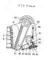
- FIG. 9 is an explanatory view of a sectional side view of a jaw crusher disclosed in Japanese Patent Application Laid-open No. 10-249224.
- a swing jaw 61 having the movable jaw 5 is swingably suspended at an eccentric shaft 62 attached at upper portions of left and right side frames 80 and 80, and the stationary jaw 3 is fixedly provided at the side frame 80 to oppose it to form a crushing chamber 6.
- a toggle block 63 is attached to the side frame 80 by a block support shaft 81 with its base end portion being rotatable.
- a window 82 having a semicircular portion is provided near a tip end portion of the toggle block 63 at the side frame 80, a semicircular disc-shaped load supporting plate 83 is fitted in the window 82, and a set adjusting plate 84 for adjusting an outlet clearance of the crushing chamber 6 is provided between the load supporting plate 83 and the toggle block 63.
- Toggle sheets 66 and 66 each having a groove portion are attached to a lower end portion of the swing jaw 61 and the toggle block 63.
- a toggle plate 67 is provided between groove portions of both the sheets 66 and 66 so that both ends thereof is slidable, and the lower end portion of the swing jaw 61 is always biased to the toggle block 63 by a spring 85.
- the toggle block 63 and the side frame 80 are connected by a bare rock type of hydraulic cylinder 86, the toggle block 63 is rotated by a hydraulic cylinder 86 at the time of adjusting the outlet clearance of the crushing chamber 6, and a clearance is provided between the toggle block 63 and the load supporting plate 83 so that the thickness of the set adjusting plate 84 is adjusted.
- the toggle sheets 66 and 66 are attached to the lower end portion of the swing jaw 61 and the toggle block 63, and the toggle plate 67 is held between both the sheets 66 and 66 to receive a load during crushing. Accordingly, the toggle plate 67 is sandwiched, and the springs 68 and 85 are used to hold it, which makes the structures complicated, requires adjustment of the springs 68 and 85 each time the tip clearance is adjusted, thus increasing adjustment time. In addition, when they are mounted on vehicles, operating spaces become narrow, which makes adjusting operations themselves difficult.
- the adjusting hydraulic cylinder 71 is provided at the rear end portion of the hydraulic actuator 70, the total length of the hydraulic cylinder part is long, and since it is horizontally arranged, a total length N of the jaw crusher 61 shown in FIG. 8 is long, which makes a space area large to cause the disadvantage when mounted on a vehicle and the like. Since pressure is always applied to the adjusting hydraulic cylinder 71, energy is wasted. Further, oil leakage occurs, which makes it unstable. A complicated hydraulic circuit structure is necessary to prevent the oil leakage, which makes it expensive.
- the toggle plate 67 is sandwiched, and the springs 68 and 85 are used to hold it, which makes the structures complicated, requires adjustment of the springs 68 and 85 each time the tip clearance is adjusted, thus increasing adjustment time.
- the toggle plate 67 is bent under excessive load, and a replacement operation of the bent toggle plate 67 is difficult, thus requiring a great deal of time.
- adjustment of the outlet clearance of the crushing chamber 6 is made with the set adjustment plate 84, a great deal of time is required for adjustment and thus operation efficiency is low.
- a jaw crusher of the initially-mentioned type and having the features of the preamble of claim 1 is known from DE 44 00 922 A.
- the present invention is made in view of the above-described disadvantages, and has its object to provide a compact and light-weight jaw crusher in which life span of parts enduring abrasion is long, a structure is simple, less part is damaged under excessive load with excellent operation efficiency, greater economy is obtained with no energy loss, and an outlet clearance of a crushing chamber is easily adjusted.
- the swingable coupling joint which never comes off and falls, is used for the connecting member for the lower end portion of the movable jaw which receives load during compression crushing of the jaw crusher and the movable jaw load receiving section attached to the frame. Consequently, since the attached spring is not needed, the structure is simplified, and the tip clearance adjusting time can be shortened. Further, the lubrication at the connecting portion is secured, and the frequency of maintenance is reduced with less abrasion, thus improving operation efficiency.
- the structure including a hydraulic circuit which makes the hydraulic cylinder with the close fit mechanism open at a time of crushing operation may be made.
- the hydraulic cylinder with the close fit mechanism has the structure having the close fit mechanism of the piston and the cylinder.
- the hydraulic cylinder with the close fit mechanism has the close fit mechanism of the piston and the cylinder, the relative movement in the axial direction is locked with the frictional force by the close fitting and the length in the axial direction is made changeable by hydraulic pressure applied to both end portions of the piston.
- a large locking force can be obtained with a small size and the total length can be reduced, thus making it possible to reduce the apparatus in size.
- the hydraulic cylinder with the close fit mechanism has the close fit mechanism of the piston and the cylinder, locks the relative movement in the axial direction with the friction force by the close fitting, and makes the length in the axial direction changeable by the hydraulic pressure applied to both end portions of the piston, thus making it possible to obtain a large locking force with a small size, reduce the total length, and make the apparatus compact.
- the structure in which one end portion of the hydraulic cylinder with the close fit mechanism is attached to the frame near the eccentric drive shaft may be made.
- one end portion of the hydraulic cylinder with the close fit mechanism is attached to the frame near the eccentric drive shaft having rigidity, and therefore special reinforcement of the frame for attachment of the hydraulic cylinder becomes unnecessary, thus making it possible to reduce in weight. Further, placement in the substantially vertical direction is made possible, whereby the total length of the jaw crusher can be reduced, the frame can be reduced in weight, and the jaw crusher can be easily mounted on a vehicle.
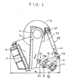
- FIG. 1 is a partial sectional side view showing an example of a jaw crusher 1.
- a stationary jaw 3 is attached between a pair of left and right frames 2 and 2
- a movable jaw 5 is swingably suspended at an eccentric drive shaft 4 provided at frames 2 and 2 at a position opposing the stationary jaw 3, whereby a crushing chamber 6 is formed between the stationary jaw 3 and the movable jaw 5.
- a movable jaw load receiving section 10 forming a link mechanism is provided at a back of the movable jaw 5 between the frames 2 and 2.
- a longitudinal middle portion of a lever 12 is swingably attached to a bracket 11 fixedly provided at the frames 2 and 2 by means of a first pin 13.
- One end portion of a link 20 is attached to one end portion of the lever 12 by means of a second pin 21 as an example of a pin coupling joint, and the other end portion of the link 20 is rotatably connected to a lower portion of the back side of the movable jaw 5 by means of a third pin 23a as an example of the pin coupling joint.
- the link 20, the second pin 21 and the third pin 23a form a coupling joint 23 for swingably connecting the lower portion of the movable jaw 5 and the movable jaw load receiving section 10.
- the other end portion of the lever 12 is rotatably connected to a tip end portion of a piston rod 41 of a hydraulic cylinder 40 with a close fit mechanism by means of a fourth pin 25.
- the hydraulic cylinder 40 with the close fit mechanism is placed with its cylinder shaft being faced in substantially a vertical direction, and its base end portion is rotatably attached to an upper portion of the frame 2 by means of a fifth pin 27.
- a reaction force occurring when an object to be crushed is crushed in the crushing chamber 6 is transmitted to the hydraulic cylinder 40 with the close fit mechanism via the link 20 and the lever 12.
- the lever 12, the hydraulic cylinder 40 with the close fit mechanism, the bracket 11 and each of the connecting pins 13, 25 and 27 form the movable jaw load receiving section 10.
- the eccentric drive shaft 4, the movable jaw load receiving section 10 and the coupling joint 23 constitute a movable jaw holding mechanism for holding the movable jaw 5 at the frame 2.
- the coupling joint 23 is an example of a connecting member for connecting the movable jaw 5 and the movable jaw load receiving section 10.
- FIG. 2 is a sectional view taken along the line 2-2 in FIG. 1, and the detail of a connecting portion of the link 20 and the lever 12 will be explained with reference to FIG. 2.
- two of the aforementioned brackets 11, levers 12, links 20, and hydraulic cylinders 40 each with the close fit mechanism, having the same structure, are provided in parallel on the left and right (up and down in FIG. 2) of the movable jaw 5.
- a first bush 14 is provided between the bracket 11 and the first pin 13, and lubricant oil is supplied to the first bush 14 from a nipple 15.
- a second bush 22 is provided between the one end portion of the link 20 and the second pin 21, and lubricant oil is supplied to the second bush 22 from a nipple 15a.
- a third bush 24 is provided between the other end portion of the link 20 and the third pin 23a, and lubricant oil is supplied to the third bush 24 from a nipple 15b.
- a ball bearing 26 is provided at the forth pin 25 portion for connecting the other end portion of the lever 12 and the tip end portion of the piston rod 41 of the hydraulic cylinder 40 with the close fit mechanism.
- FIG. 3 is a sectional view of the hydraulic cylinder 40 with the close fit mechanism.
- a piston 43 having a piston rod 41 is pressed into a cylinder 42.
- An oil hole 44 is formed in the piston rod 41, and the oil hole 44 is communicated with an outside surface of the piston 43.
- FIG. 3 shows a state in which pressure oil is not supplied to the oil hole 44 from outside, and in this state, the piston 43 is in a fixed position with frictional resistance with the cylinder 42.
- pressure oil is supplied into the oil hole 44 so that the cylinder 42 area at the outer circumferential part of the piston 43 is expanded as a section P shown in FIG. 4 to expand the inner diameter.
- the frictional resistance between the piston 43 and the cylinder 42 is reduced, whereby the press fitting force of the piston 43 is reduced, and subsequently, the pressure oil is supplied to a cylinder head chamber 45 or a cylinder bottom chamber 46 to thereby move the piston 43.
- a first electromagnetic change-over valve 52 is provided on a piston circuit 51 for connecting the oil hole 44 of the piston rod 41 of the hydraulic cylinder 40 with the close fit mechanism and a first oil hydraulic source 50.
- a second electromagnetic change-over valve 56 is provided on a head circuit 54 and a bottom circuit 55 for connecting the cylinder head chamber 45 and the cylinder bottom chamber 46 of the hydraulic cylinder 40 with the close fit mechanism to a second oil hydraulic source 53.
- the first electromagnetic change-over valve 52 has two positions a and b shown in FIG. 5, the piston circuit 51 is connected to a tank 59 at the position a, and the circuit 51 is connected to a discharge circuit of the first oil hydraulic source 50 at the position b.
- the second electromagnetic change-over valve 56 has three positions c, d and e shown in FIG. 5, the head circuit 54 is connected to the second oil hydraulic source 53 at the position c, the head circuit 54 and the bottom circuit 55 are connected to the tank 59 at the position d, and the bottom circuit 55 is connected to the second oil hydraulic source 53 at the position e.
- an operation lever 57 for operating the hydraulic cylinder 40 with the close fit mechanism to contract and extend is provided, and an operation signal of the operation lever 57 is electrically connected to the first electromagnetic change-over valve 52 and the second electromagnetic change-over valve 56 via a controller 58.
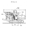
- FIG. 6 is a partial sectional view of a self-propelled jaw crusher 100 of an example, on which the jaw crusher 1 of the first embodiment is mounted.
- the jaw crusher 1 is mounted on a top portion in the middle of a traveling unit 101, and a hopper 102 is mounted in front thereof, while a power source 103 is mounted behind it. Accordingly, a total length M of the jaw crusher 1 is shorter than the length N of the conventional one shown in FIG. 8 as described above, and therefore a total length L of the self-propelled jaw crusher 100 can be made shorter and compact.
- the first electromagnetic change-over valve 52 is firstly switched into the position b to feed pressure oil into the oil hole 44 of the hydraulic cylinder 40 with the close fit mechanism to reduce the frictional force between the cylinder 42 and the piston 43.
- the second electromagnetic change-over valve 56 is switched into the position c or the position e to apply predetermined pushing pressure P1 to the head chamber 40a or the bottom chamber 40b of the hydraulic cylinder 40 with the close fit mechanism to contract or extend the hydraulic cylinder 40 with the close fit mechanism.
- the movable jaw 5 is swung via the lever 12 and the coupling joint 23 to adjust an outlet clearance S at the tip end portion of the stationary jaw 3 and the movable jaw 5 shown in FIG. 1 in accordance with a product.
- the second electromagnetic change-over valve 56 is switched into the position d to connect the head circuit 54 and the bottom circuit 55 to the tank 59, and the head chamber 40a and the bottom chamber 40b of the hydraulic cylinder 40 with the close fit mechanism are opened to make the pushing pressure P1 zero.
- the movable jaw load receiving section 10 (the lever 12, the hydraulic cylinder 40 with the close fit mechanism, the bracket 11 and each of the connecting pins 13, 25 and 27) and the coupling joint 23 form a part of the clearance adjusting mechanism.
- the jaw crusher 1 according to the first embodiment of the present invention is constituted as described above, the following effects can be obtained.
- the structure is simplified, and lubrication of the connecting portion can be surely made, whereby abrasion is reduced and thus the frequency of maintenance is reduced, thus improving operation efficiency.
- the hydraulic cylinder 40 with the close fit mechanism includes the cylinder 42, the piston 43 and the piston rod 41, it locks the relative movement in the axial direction by the frictional force by the close fitting of the piston 43 and the cylinder 42, and it makes the axial length changeable by the hydraulic pressure applied to both end portions of the piston 43. As a result, large locking power can be obtained with the smaller size, and the total length can be reduced, thus reducing the apparatus in size and weight.
- the pressure oil is not applied to the hydraulic cylinder 40 with the close fit mechanism during a crushing operation, greater economy is obtained with no energy loss, and an accumulator for holding the pressure oil, a leakage prevention valve and the like are not needed in the hydraulic circuit, whereby the circuit is simplified and the cost is reduced.
- the shaft of the hydraulic cylinder 40 with the close fit mechanism is placed in the substantially vertical direction, the total length M of the jaw crusher 1 can be reduced, whereby the frame 2 can be reduced in weight and the vehicle can be made compact when it is mounted thereon.
- the connecting portion (the fifth pin 27 portion) with the frame 2 is provided near the eccentric drive shaft 4 having rigidity, special rigidity reinforcement for the frame 2 is not needed and weight reduction can be realized.
- pin coupling (by the third pin 23a shown in the drawing) is used for the coupling joint 23 of the lower portion of the movable jaw 5 and the movable jaw load receiving section 10, but they may be connected with a trunnion joint, a universal joint, a joint with use of a ball bearing or the like.
- An example in which two of the brackets 11, the levers 12, the links 20 and the hydraulic cylinders 40 each with the close fit mechanism are provided in parallel is shown, but this is not restrictive, and they may be constituted by an integrated one or by each single unit of them.
- the piston rod 41 of the hydraulic cylinder 40 with the close fit mechanism may be attached in the opposite direction.
- the number of links of the movable jaw load receiving section 10 forming the link mechanism is not limited to the above-described embodiment.
- a stationary jaw 3 is attached to a pair of left and right frames 2 and 2, and a movable jaw 5 is suspended to be swingable by an eccentric drive shaft 4 provided at the frames 2 and 2.
- a lower portion of the movable jaw 5 and a movable jaw load receiving section 10 are swingably connected by a coupling joint 23 as an example of a connecting member for connecting both components, which is constituted by a link 20 and pins 21 and 23a.
- the movable jaw load receiving section 10 includes a toggle block 31, a hydraulic cylinder 30, a pedestal 32 and a shim 33.
- the toggle block 31 is slidably mounted on the pedestal 32, and includes, at the side of the pedestal 32, a protruded part 31a (as shown in FIG. 7, the protruded part with a V-shaped section) with a top surface being a downward inclined plane toward the direction away from the movable jaw 5, as shown in FIG. 7.
- the pedestal 32 has, at the side of the toggle block 31, a V-shaped opening 32a which has the shape conforming to the protruded part 31a and is capable of being in contact with the protruded part 31a.
- the pedestal 32 has the shim 33, which can be freely taken in and out, between the downward inclined plane of the toggle block 31 and the pedestal 32.
- Both end portions of left and right hydraulic cylinders 30 and 30 in a plan view are connected with pins between the toggle block 31 and the pedestal 32. Either one of the front and rear pin connection parts of the hydraulic cylinders 30 and 30 is connected with a horizontal pin as shown in FIG. 7 (in FIG.
- the tip clearance adjusting mechanism in the second embodiment is as follows. Specifically, at the time of adjusting the tip clearance S, the lower portion of the movable jaw 5 is moved via the coupling joint 23 by contraction and extension of the hydraulic cylinder 30, and when the adjustment is completed, the shim 33 is inserted into a clearance between the downward inclined plane of the toggle block 31 and the pedestal 32. An external force in a direction to press the hydraulic cylinder 30 during crushing is received by the pedestal 32 via the link 20, the toggle block 31 and the shim 33, and therefore only the oil pressure which overcomes the external force in a direction to pull the hydraulic cylinder 30 (usually, smaller than the external force in the aforementioned pressing direction) may be applied.
- the following effect can be obtained. Since the lower portion of the movable jaw 5 and the movable jaw load receiving section 10 are swingably connected by the coupling joint 23 such as pin connection, a spring for holding and contacting the toggle plate as in the prior art is made unnecessary. As a result, abrasion of the connecting portion between the movable jaw 5 and the movable jaw load receiving section 10 is reduced, which improves durability and maintainability to improve operation efficiency, and adjustment of the spring after the tip clearance adjustment is made unnecessary, thus making it possible to reduce the adjusting time.
- the hydraulic cylinder 30 moves the heavy toggle block 31 and movable jaw 5, and therefore the adjusting operation can be easily performed, thus making it possible to reduce the adjusting time.
- the oil pressure applied to the hydraulic cylinder 30 during crushing is small, only small energy consumption of the oil pressure is needed. It may be suitable to stop the oil pressure applied to the hydraulic cylinder 30, and fix the contraction and extension of the cylinder 30 with a bolt or the like. In this case, the number of man-hours is increased a little due to attachment and detachment of the bolt or the like, but energy consumption of the oil pressure is eliminated.
- the connecting member for connecting the lower portion of the movable jaw and the movable jaw load receiving section As the connecting member for connecting the lower portion of the movable jaw and the movable jaw load receiving section, the coupling joint for connecting the both components swingably with a pin or the like is used, and therefore the abrasion of the connecting portion is decreased, thus making it possible to reduce the frequency of maintenance and improve the operation efficiency of the jaw crusher.
- the spring mechanism for preventing the connection member from being detached is unnecessary, and therefore the spring adjustment after the jaw tip clearance adjustment is unnecessary, thus making it possible to reduce adjusting time and improve the operation efficiency.
- the adjustment operation can be carried out with ease and facilitated, and therefore adjusting time can be reduced. Since the oil pressure applied to the hydraulic cylinder during the crushing operation may be zero (in the case of the hydraulic cylinder with the close fit mechanism), or may be small (in the case of combination of the pedestal, toggle block and the hydraulic cylinder), energy loss of the pressure oil can be reduced.
- the close fit friction part of the hydraulic cylinder with the close fit mechanism can slide under excessive load and absorb the excessive load, the breakage of the frame, movable jaw, the connecting member and the like can be prevented.
- the movement of the piston is locked with friction caused by the close fit mechanism of the piston and the cylinder, and therefore the hydraulic cylinder with the close fit mechanism can be reduced in size.
- the frame can be reduced in weight and can be placed in the substantially vertical direction, whereby the total length of the jaw crusher can be reduced, the frame can be reduced in weight and the jaw crusher can be easily mounted on a vehicle.
Landscapes
- Engineering & Computer Science (AREA)
- Food Science & Technology (AREA)
- Mechanical Engineering (AREA)
- Crushing And Grinding (AREA)
- Saccharide Compounds (AREA)
Claims (3)
- Backenbrecher, aufweisend:einen Rahmen (2);eine feststehende Backe (3), die an dem Rahmen (2) fest vorgesehen ist; undeine schwenkbare Backe (5), welche der feststehenden Backe (3) gegenüberliegend vorgesehen ist, und welche an einem oberen Abschnitt mit einer exzentrischen Antriebswelle (4) schwenkbar verbunden ist und welche an einem unteren Abschnitt mittels eines Gelenkmechanismus mit einem Backenstützbereich an dem Rahmen (2) verbunden ist, wobei der Gelenkmechanismus aufweist: einen Hebel (12), der mit dem Backenstützbereich schwenkbar verbunden ist, ein Verbindungsstück (20), das mit dem unteren Abschnitt der schwenkbaren Backe (5) schwenkbar verbunden ist und mit dem Hebel (12) schwenkbar verbunden ist, um zu ermöglichen, dass die schwenkbare Backe (5) von der exzentrischen Antriebswelle (4) schwenkbar angetrieben wird, und einen Hydraulikzylinder (40), der an seinem einen Endabschnitt mit dem Rahmen (2) schwenkbar verbunden ist und an seinem anderen Endabschnitt mit dem Hebel (12) verbunden ist, um den Gelenkmechanismus und dadurch die Position der schwenkbaren Backe (5) einzustellen und zu blockieren, dadurch gekennzeichnet, dassder Hydraulikzylinder (40) einen Feinpassungsmechanismus aufweist, wobei der Kolben (43) im Blockierzustand des Hydraulikzylinders (40) mittels eines Reibungswiderstandes zwischen dem Kolben (43) und dem Zylindergehäuse (42) in einer fixierten Position ist, und wobei der Kolben (43), wenn der Hydraulikzylinder (40) ein- oder auszufahren ist, bewegbar gemacht werden kann durch Zuführen von Drucköl zu einem Außenumfangsteil des Kolbens (43) und Erweitern eines Innendurchmessers des Zylindergehäuses (42), um dadurch den Reibungswiderstand zwischen dem Kolben (43) und dem Zylindergehäuse (42) zu reduzieren.
- Backenbrecher nach Anspruch 1, dadurch gekennzeichnet, dass der Hydraulikzylinder (40) mit einer Hydraulikschaltung versehen ist, welche beim Brechvorgang sowohl eine Kopfkammer (40a) als auch eine Bodenkammer (40b) des Hydraulikzylinders (40) mit einem Behälter (59) verbindet, um einen Stoßdruck des Kolben (43) auf Null zu reduzieren.
- Backenbrecher nach Anspruch 1 oder 2, dadurch gekennzeichnet, dass der Hydraulikzylinder (40) an seinem einen Endabschnitt mit dem Rahmen (2) in der Nähe der exzentrischen Antriebswelle (4) verbunden ist.
Applications Claiming Priority (2)
| Application Number | Priority Date | Filing Date | Title |
|---|---|---|---|
| JP2001246894A JP2003053203A (ja) | 2001-08-16 | 2001-08-16 | ジョークラッシャ |
| JP2001246894 | 2001-08-16 |
Publications (2)
| Publication Number | Publication Date |
|---|---|
| EP1285696A1 EP1285696A1 (de) | 2003-02-26 |
| EP1285696B1 true EP1285696B1 (de) | 2005-12-07 |
Family
ID=19076338
Family Applications (1)
| Application Number | Title | Priority Date | Filing Date |
|---|---|---|---|
| EP02017752A Expired - Lifetime EP1285696B1 (de) | 2001-08-16 | 2002-08-08 | Backenbrecher |
Country Status (7)
| Country | Link |
|---|---|
| US (1) | US6644577B2 (de) |
| EP (1) | EP1285696B1 (de) |
| JP (1) | JP2003053203A (de) |
| KR (1) | KR100870223B1 (de) |
| CN (1) | CN1265886C (de) |
| AT (1) | ATE311936T1 (de) |
| DE (1) | DE60207792T2 (de) |
Families Citing this family (21)
| Publication number | Priority date | Publication date | Assignee | Title |
|---|---|---|---|---|
| JP3788427B2 (ja) * | 2002-12-26 | 2006-06-21 | 河 龍干 | ジョークラッシャー |
| US7344097B2 (en) * | 2005-03-14 | 2008-03-18 | Cedarapids, Inc. | Jaw-type rock crusher with toggle plate tension bar |
| WO2007026590A1 (ja) * | 2005-08-29 | 2007-03-08 | Komatsu Ltd. | ジョークラッシャおよび自走式破砕機 |
| JP4879903B2 (ja) * | 2005-08-29 | 2012-02-22 | 株式会社小松製作所 | ジョークラッシャおよび自走式破砕機 |
| JP4712527B2 (ja) * | 2005-11-02 | 2011-06-29 | 日立建機株式会社 | ジョークラッシャ |
| US7942355B2 (en) | 2006-05-10 | 2011-05-17 | Komatsu Ltd. | Self-propelled crusher and management system for self-propelled crusher |
| CN101607220B (zh) * | 2008-06-20 | 2012-08-29 | 启铭机械股份有限公司 | 颚碎机 |
| AT509476B1 (de) * | 2010-03-11 | 2013-04-15 | Hartl Stefan | Backenbrecher |
| KR101167186B1 (ko) | 2010-08-23 | 2012-07-24 | (주)대성하이텍 | 분쇄기용 분쇄통의 착탈장치 |
| CN103706422A (zh) * | 2012-10-02 | 2014-04-09 | 义乌市多方联矿机超市有限公司 | 一种用于颚式破碎机的铰接式肘杆 |
| CN103706425A (zh) * | 2012-10-02 | 2014-04-09 | 义乌市多方联矿机超市有限公司 | 一种免除了弹簧拉杆机构的颚式破碎机 |
| US9901929B2 (en) | 2015-08-05 | 2018-02-27 | Harry Irving | Jaw crusher machine |
| USD823360S1 (en) * | 2017-06-20 | 2018-07-17 | Sandvik Intellectual Property Ab | Jaw crusher front frame end |
| CN107737776A (zh) * | 2017-11-29 | 2018-02-27 | 沈阳汇丰机械有限公司 | 残阳极表面预破碎装置 |
| DE102018110265B4 (de) | 2018-04-27 | 2024-03-21 | Kleemann Gmbh | Backenbrecher |
| CN108671992A (zh) * | 2018-05-18 | 2018-10-19 | 广西联壮科技股份有限公司 | 一种陶瓷机械斗形破碎机构 |
| CN109847831B (zh) * | 2018-11-30 | 2020-09-22 | 沂南县宝石硅砂有限公司 | 一种瞬时冲击辅助式鄂式破碎板 |
| US11602755B2 (en) * | 2019-08-27 | 2023-03-14 | Eagle Crusher Company, Inc. | Crusher with resettable relief system |
| CN111298893B (zh) * | 2020-03-11 | 2024-07-16 | 塞尔姆(北京)科技有限责任公司 | 一种平头辊破碎机调节装置 |
| CN115628241B (zh) * | 2022-11-30 | 2026-02-06 | 徐州徐工矿业机械有限公司 | 一种多功能破碎主机试验装置 |
| CN117548167B (zh) * | 2024-01-11 | 2024-04-12 | 扬州环锐科技有限公司 | 一种矿石破碎机及其监控系统 |
Family Cites Families (18)
| Publication number | Priority date | Publication date | Assignee | Title |
|---|---|---|---|---|
| GB789365A (en) | 1955-06-08 | 1958-01-22 | Kloeckner Humboldt Deutz Ag | A jaw crusher |
| FR2460716A1 (fr) * | 1979-07-06 | 1981-01-30 | Fives Cail Babcock | Concasseur ou broyeur a machoires muni d'un systeme de reglage et de securite |
| JPS6248434U (de) * | 1985-09-10 | 1987-03-25 | ||
| US4679742A (en) * | 1985-11-18 | 1987-07-14 | Ian Gordon Rodger | Crusher having opposed and balanced driver jaws |
| DE3803496C1 (de) * | 1988-02-05 | 1989-06-01 | Paul 7101 Oedheim De Boehringer | |
| JP2798267B2 (ja) * | 1989-07-21 | 1998-09-17 | テルモ株式会社 | γ線滅菌可能な親水化多孔質体 |
| JP3025065B2 (ja) | 1991-08-15 | 2000-03-27 | 日本電信電話株式会社 | 欠陥箇所表示処理方法 |
| US5730373A (en) * | 1993-12-28 | 1998-03-24 | Komatsu Ltd. | Crusher system drive control apparatus for a traveling type crushing machine |
| DE4400922A1 (de) | 1994-01-14 | 1995-03-30 | Krupp Foerdertechnik Gmbh | Backenbrecher mit einer Einrichtung zum Schutz gegen Überlastung und zum Einstellen der Brechspaltweite |
| JP3165785B2 (ja) * | 1996-03-29 | 2001-05-14 | ジャクティ・エンジニアリング株式会社 | ジョークラッシャ |
| JP2945346B2 (ja) * | 1997-03-07 | 1999-09-06 | 川崎重工業株式会社 | ジョークラッシャ |
| US6116530A (en) * | 1999-06-21 | 2000-09-12 | E & E Seegmiller Limited | Adapter for rock crusher |
| US6375105B1 (en) * | 2000-03-21 | 2002-04-23 | Astec Industries, Inc. | Jaw crusher toggle beam hydraulic relief and clearing |
| KR200195975Y1 (ko) * | 2000-03-30 | 2000-09-15 | 정인관 | 파쇄용 조 크러셔 |
| JP4247807B2 (ja) * | 2000-09-26 | 2009-04-02 | 株式会社小松製作所 | ジョークラッシャの出口隙間調整機構 |
| GB0025888D0 (en) | 2000-10-23 | 2000-12-06 | Extec Ind Plc | Jaw crusher unit |
| KR200292661Y1 (ko) * | 2002-07-08 | 2002-10-25 | 정태현 | 죠 크러셔용 스윙 죠 조절 구조 |
| JP3788427B2 (ja) * | 2002-12-26 | 2006-06-21 | 河 龍干 | ジョークラッシャー |
-
2001
- 2001-08-16 JP JP2001246894A patent/JP2003053203A/ja active Pending
-
2002
- 2002-07-13 KR KR1020020040963A patent/KR100870223B1/ko not_active Expired - Fee Related
- 2002-07-18 US US10/197,535 patent/US6644577B2/en not_active Expired - Lifetime
- 2002-08-08 DE DE60207792T patent/DE60207792T2/de not_active Expired - Lifetime
- 2002-08-08 AT AT02017752T patent/ATE311936T1/de not_active IP Right Cessation
- 2002-08-08 EP EP02017752A patent/EP1285696B1/de not_active Expired - Lifetime
- 2002-08-16 CN CNB021305668A patent/CN1265886C/zh not_active Expired - Fee Related
Also Published As
| Publication number | Publication date |
|---|---|
| DE60207792T2 (de) | 2006-08-03 |
| KR20030015839A (ko) | 2003-02-25 |
| US20030034412A1 (en) | 2003-02-20 |
| CN1265886C (zh) | 2006-07-26 |
| ATE311936T1 (de) | 2005-12-15 |
| EP1285696A1 (de) | 2003-02-26 |
| JP2003053203A (ja) | 2003-02-25 |
| KR100870223B1 (ko) | 2008-11-24 |
| DE60207792D1 (de) | 2006-01-12 |
| CN1406667A (zh) | 2003-04-02 |
| US6644577B2 (en) | 2003-11-11 |
Similar Documents
| Publication | Publication Date | Title |
|---|---|---|
| EP1285696B1 (de) | Backenbrecher | |
| EP1190772B1 (de) | Vorrichtung zum Justieren des Auslasspiels eines Backenbrechers und selbsfahrende Zerkleinerungsmaschine mit einer solchen Vorrichtung | |
| US5359775A (en) | Steel-material shearing machine | |
| US5799888A (en) | Jaw crusher | |
| CA2374679C (en) | A quick coupling | |
| US8491251B2 (en) | Gripping device of working machine and working machine with the same | |
| JP2682860B2 (ja) | 迅速連結機内の装置 | |
| US6331010B1 (en) | Structure for supporting cylinders | |
| KR20080091437A (ko) | 시저 잭 | |
| CN214888786U (zh) | 地面加工机和支承结构 | |
| US5975605A (en) | Enclosed clamping or gripping device with accessible load controlling spring | |
| CA2437169A1 (en) | Linkage for on-off loading and dumping of a dumpster on a truck frame | |
| JP2808236B2 (ja) | ジョ−クラッシャのトグルブロック位置調整方法及びその方法に用いる装置 | |
| JP2002511914A (ja) | アキシャルピストン機械 | |
| KR20010013196A (ko) | 연속 주조 장비 | |
| JP4778640B2 (ja) | ジョークラッシャ | |
| JP2009501660A (ja) | コンバーチブルのソフトトップコンパートメントカバー用の支持装置 | |
| US6248288B1 (en) | Rotating mechanism with arm | |
| WO2007015283A1 (en) | Load shifting device for an articulated vehicle | |
| JP3324957B2 (ja) | 鍛造プレス機のスライド調整構造 | |
| US6109181A (en) | Inking device for printing machine | |
| CN101277771B (zh) | 具有移动装置的轧机机座 | |
| CN210502862U (zh) | 一种轮转向式半挂车转向装置 | |
| JPH0988808A (ja) | アキシァル斜板形ポンプ・モータ | |
| US20210062466A1 (en) | Loader |
Legal Events
| Date | Code | Title | Description |
|---|---|---|---|
| PUAI | Public reference made under article 153(3) epc to a published international application that has entered the european phase |
Free format text: ORIGINAL CODE: 0009012 |
|
| 17P | Request for examination filed |
Effective date: 20020808 |
|
| AK | Designated contracting states |
Kind code of ref document: A1 Designated state(s): AT BE BG CH CY CZ DE DK EE ES FI FR GB GR IE IT LI LU MC NL PT SE SK TR |
|
| AX | Request for extension of the european patent |
Extension state: AL LT LV MK RO SI |
|
| AKX | Designation fees paid |
Designated state(s): AT BE BG CH CY CZ DE DK EE ES FI FR GB GR IE IT LI LU MC NL PT SE SK TR |
|
| 17Q | First examination report despatched |
Effective date: 20040324 |
|
| GRAP | Despatch of communication of intention to grant a patent |
Free format text: ORIGINAL CODE: EPIDOSNIGR1 |
|
| GRAS | Grant fee paid |
Free format text: ORIGINAL CODE: EPIDOSNIGR3 |
|
| GRAA | (expected) grant |
Free format text: ORIGINAL CODE: 0009210 |
|
| AK | Designated contracting states |
Kind code of ref document: B1 Designated state(s): AT BE BG CH CY CZ DE DK EE ES FI FR GB GR IE IT LI LU MC NL PT SE SK TR |
|
| PG25 | Lapsed in a contracting state [announced via postgrant information from national office to epo] |
Ref country code: IT Free format text: LAPSE BECAUSE OF FAILURE TO SUBMIT A TRANSLATION OF THE DESCRIPTION OR TO PAY THE FEE WITHIN THE PRESCRIBED TIME-LIMIT;WARNING: LAPSES OF ITALIAN PATENTS WITH EFFECTIVE DATE BEFORE 2007 MAY HAVE OCCURRED AT ANY TIME BEFORE 2007. THE CORRECT EFFECTIVE DATE MAY BE DIFFERENT FROM THE ONE RECORDED. Effective date: 20051207 Ref country code: CH Free format text: LAPSE BECAUSE OF FAILURE TO SUBMIT A TRANSLATION OF THE DESCRIPTION OR TO PAY THE FEE WITHIN THE PRESCRIBED TIME-LIMIT Effective date: 20051207 Ref country code: BE Free format text: LAPSE BECAUSE OF FAILURE TO SUBMIT A TRANSLATION OF THE DESCRIPTION OR TO PAY THE FEE WITHIN THE PRESCRIBED TIME-LIMIT Effective date: 20051207 Ref country code: CZ Free format text: LAPSE BECAUSE OF FAILURE TO SUBMIT A TRANSLATION OF THE DESCRIPTION OR TO PAY THE FEE WITHIN THE PRESCRIBED TIME-LIMIT Effective date: 20051207 Ref country code: NL Free format text: LAPSE BECAUSE OF FAILURE TO SUBMIT A TRANSLATION OF THE DESCRIPTION OR TO PAY THE FEE WITHIN THE PRESCRIBED TIME-LIMIT Effective date: 20051207 Ref country code: LI Free format text: LAPSE BECAUSE OF FAILURE TO SUBMIT A TRANSLATION OF THE DESCRIPTION OR TO PAY THE FEE WITHIN THE PRESCRIBED TIME-LIMIT Effective date: 20051207 Ref country code: SK Free format text: LAPSE BECAUSE OF FAILURE TO SUBMIT A TRANSLATION OF THE DESCRIPTION OR TO PAY THE FEE WITHIN THE PRESCRIBED TIME-LIMIT Effective date: 20051207 |
|
| REG | Reference to a national code |
Ref country code: GB Ref legal event code: FG4D |
|
| REG | Reference to a national code |
Ref country code: CH Ref legal event code: EP |
|
| REG | Reference to a national code |
Ref country code: IE Ref legal event code: FG4D |
|
| REF | Corresponds to: |
Ref document number: 60207792 Country of ref document: DE Date of ref document: 20060112 Kind code of ref document: P |
|
| PG25 | Lapsed in a contracting state [announced via postgrant information from national office to epo] |
Ref country code: SE Free format text: LAPSE BECAUSE OF FAILURE TO SUBMIT A TRANSLATION OF THE DESCRIPTION OR TO PAY THE FEE WITHIN THE PRESCRIBED TIME-LIMIT Effective date: 20060307 Ref country code: DK Free format text: LAPSE BECAUSE OF FAILURE TO SUBMIT A TRANSLATION OF THE DESCRIPTION OR TO PAY THE FEE WITHIN THE PRESCRIBED TIME-LIMIT Effective date: 20060307 Ref country code: GR Free format text: LAPSE BECAUSE OF FAILURE TO SUBMIT A TRANSLATION OF THE DESCRIPTION OR TO PAY THE FEE WITHIN THE PRESCRIBED TIME-LIMIT Effective date: 20060307 Ref country code: BG Free format text: LAPSE BECAUSE OF FAILURE TO SUBMIT A TRANSLATION OF THE DESCRIPTION OR TO PAY THE FEE WITHIN THE PRESCRIBED TIME-LIMIT Effective date: 20060307 |
|
| PG25 | Lapsed in a contracting state [announced via postgrant information from national office to epo] |
Ref country code: ES Free format text: LAPSE BECAUSE OF FAILURE TO SUBMIT A TRANSLATION OF THE DESCRIPTION OR TO PAY THE FEE WITHIN THE PRESCRIBED TIME-LIMIT Effective date: 20060318 |
|
| PG25 | Lapsed in a contracting state [announced via postgrant information from national office to epo] |
Ref country code: PT Free format text: LAPSE BECAUSE OF FAILURE TO SUBMIT A TRANSLATION OF THE DESCRIPTION OR TO PAY THE FEE WITHIN THE PRESCRIBED TIME-LIMIT Effective date: 20060508 |
|
| NLV1 | Nl: lapsed or annulled due to failure to fulfill the requirements of art. 29p and 29m of the patents act | ||
| REG | Reference to a national code |
Ref country code: CH Ref legal event code: PL |
|
| PG25 | Lapsed in a contracting state [announced via postgrant information from national office to epo] |
Ref country code: IE Free format text: LAPSE BECAUSE OF NON-PAYMENT OF DUE FEES Effective date: 20060808 |
|
| PGFP | Annual fee paid to national office [announced via postgrant information from national office to epo] |
Ref country code: AT Payment date: 20060811 Year of fee payment: 5 |
|
| PG25 | Lapsed in a contracting state [announced via postgrant information from national office to epo] |
Ref country code: MC Free format text: LAPSE BECAUSE OF NON-PAYMENT OF DUE FEES Effective date: 20060831 |
|
| PLBE | No opposition filed within time limit |
Free format text: ORIGINAL CODE: 0009261 |
|
| STAA | Information on the status of an ep patent application or granted ep patent |
Free format text: STATUS: NO OPPOSITION FILED WITHIN TIME LIMIT |
|
| 26N | No opposition filed |
Effective date: 20060908 |
|
| EN | Fr: translation not filed | ||
| REG | Reference to a national code |
Ref country code: IE Ref legal event code: MM4A |
|
| PG25 | Lapsed in a contracting state [announced via postgrant information from national office to epo] |
Ref country code: FR Free format text: LAPSE BECAUSE OF FAILURE TO SUBMIT A TRANSLATION OF THE DESCRIPTION OR TO PAY THE FEE WITHIN THE PRESCRIBED TIME-LIMIT Effective date: 20070126 |
|
| PG25 | Lapsed in a contracting state [announced via postgrant information from national office to epo] |
Ref country code: AT Free format text: LAPSE BECAUSE OF NON-PAYMENT OF DUE FEES Effective date: 20070808 Ref country code: EE Free format text: LAPSE BECAUSE OF FAILURE TO SUBMIT A TRANSLATION OF THE DESCRIPTION OR TO PAY THE FEE WITHIN THE PRESCRIBED TIME-LIMIT Effective date: 20051207 |
|
| PG25 | Lapsed in a contracting state [announced via postgrant information from national office to epo] |
Ref country code: LU Free format text: LAPSE BECAUSE OF NON-PAYMENT OF DUE FEES Effective date: 20060808 Ref country code: TR Free format text: LAPSE BECAUSE OF FAILURE TO SUBMIT A TRANSLATION OF THE DESCRIPTION OR TO PAY THE FEE WITHIN THE PRESCRIBED TIME-LIMIT Effective date: 20051207 |
|
| PG25 | Lapsed in a contracting state [announced via postgrant information from national office to epo] |
Ref country code: CY Free format text: LAPSE BECAUSE OF FAILURE TO SUBMIT A TRANSLATION OF THE DESCRIPTION OR TO PAY THE FEE WITHIN THE PRESCRIBED TIME-LIMIT Effective date: 20051207 Ref country code: FR Free format text: LAPSE BECAUSE OF FAILURE TO SUBMIT A TRANSLATION OF THE DESCRIPTION OR TO PAY THE FEE WITHIN THE PRESCRIBED TIME-LIMIT Effective date: 20051207 |
|
| PGFP | Annual fee paid to national office [announced via postgrant information from national office to epo] |
Ref country code: DE Payment date: 20090806 Year of fee payment: 8 Ref country code: FI Payment date: 20090813 Year of fee payment: 8 Ref country code: GB Payment date: 20090805 Year of fee payment: 8 |
|
| GBPC | Gb: european patent ceased through non-payment of renewal fee |
Effective date: 20100808 |
|
| PG25 | Lapsed in a contracting state [announced via postgrant information from national office to epo] |
Ref country code: FI Free format text: LAPSE BECAUSE OF NON-PAYMENT OF DUE FEES Effective date: 20100808 |
|
| REG | Reference to a national code |
Ref country code: DE Ref legal event code: R119 Ref document number: 60207792 Country of ref document: DE Effective date: 20110301 |
|
| PG25 | Lapsed in a contracting state [announced via postgrant information from national office to epo] |
Ref country code: DE Free format text: LAPSE BECAUSE OF NON-PAYMENT OF DUE FEES Effective date: 20110301 |
|
| PG25 | Lapsed in a contracting state [announced via postgrant information from national office to epo] |
Ref country code: GB Free format text: LAPSE BECAUSE OF NON-PAYMENT OF DUE FEES Effective date: 20100808 |