EP1285729A2 - Rotierende Rollenbürste - Google Patents
Rotierende Rollenbürste Download PDFInfo
- Publication number
- EP1285729A2 EP1285729A2 EP02255454A EP02255454A EP1285729A2 EP 1285729 A2 EP1285729 A2 EP 1285729A2 EP 02255454 A EP02255454 A EP 02255454A EP 02255454 A EP02255454 A EP 02255454A EP 1285729 A2 EP1285729 A2 EP 1285729A2
- Authority
- EP
- European Patent Office
- Prior art keywords
- drum
- key
- shaft
- rotary roll
- brush
- Prior art date
- Legal status (The legal status is an assumption and is not a legal conclusion. Google has not performed a legal analysis and makes no representation as to the accuracy of the status listed.)
- Withdrawn
Links
Images



Classifications
-
- B—PERFORMING OPERATIONS; TRANSPORTING
- B24—GRINDING; POLISHING
- B24D—TOOLS FOR GRINDING, BUFFING OR SHARPENING
- B24D13/00—Wheels having flexibly-acting working parts, e.g. buffing wheels; Mountings therefor
- B24D13/02—Wheels having flexibly-acting working parts, e.g. buffing wheels; Mountings therefor acting by their periphery
- B24D13/10—Wheels having flexibly-acting working parts, e.g. buffing wheels; Mountings therefor acting by their periphery comprising assemblies of brushes
-
- A—HUMAN NECESSITIES
- A46—BRUSHWARE
- A46B—BRUSHES
- A46B13/00—Brushes with driven brush bodies or carriers
- A46B13/001—Cylindrical or annular brush bodies
-
- A—HUMAN NECESSITIES
- A46—BRUSHWARE
- A46B—BRUSHES
- A46B2200/00—Brushes characterized by their functions, uses or applications
- A46B2200/30—Brushes for cleaning or polishing
- A46B2200/3066—Brush specifically designed for use with street cleaning machinery
Definitions
- This invention relates to a rotary roll brush designed for performing removal of slug and surface polishing with respect to a rolled steel plate or the like. Particularly, it relates to a proposal which is suited to utilize a key attached-shaft employed in a conventional roll brush which is formed by externally inserting a disc-type brush provided with a plurality of key grooves in the key-attached shaft, in a rotary roll brush in which a channel type brush is employed.
- a rotary roll brush has been formed by using a disc type brush in which a brush material is implanted in an outer peripheral edge of the disc.
- a shaft insertion hole is formed in a central area of the disc
- a key groove is formed in a disc inner peripheral edge which defines the shaft insertion hole
- a plurality of disc type brushes are externally inserted in a shaft while serving the key groove and the key formed on the shaft as a guide, thereby forming a rotary roll brush.
- a worn out used disk type rotary roll brush is supplied to a brush maker from a roll maker, etc.
- the brush maker externally inserts a new disc brush in this key-attached shaft and delivers the same to the roll maker, etc. This situation is likewise applicable to a channel type rotary roll brush to be described hereinafter.
- the key-attached shaft constituting the disc type rotary roll brush has the following inconveniences. Since the key projects over the entire length, it is impossible to wind a channel type brush around the key-attached shaft. Moreover, since the shaft with the channel type brush wound therearound is large in diameter and the key-attached shaft of the disc type rotary roll brush is small in diameter, even if an attempt is made to wind the channel type brush around the key-attached shaft after the key has been removed, it is difficult to obtain a channel type rotary roll brush having a required diameter.
- the key-attached shaft cannot be utilized as a rotary roll brush using a channel type brush which can constitute a rotary roll brush as an inexpensive manner. Therefore, a channel type rotary roll brush-specific shaft or drum is used. This puts an economic burden on the roll maker, etc.
- a channel type rotary roll brush in which a key-attached shaft is employed is formed by externally inserting a drum having a larger diameter than the key-attached shaft in the shaft.
- This rotary roll brush properly achieves an object for utilizing a shaft used for a disc type rotary roll brush as a shaft for a channel type rotary roll brush in an extremely simple manner. Moreover, an extremely inexpensive channel type rotary roll brush can be provided.
- the present invention can easily cope with difference in diameter between the shaft for the disc type rotary roll brush and the shaft for the channel type rotary roll brush.
- the drum can be inserted in and removed from the shaft.
- the drum is removed from the shaft.
- the disc type brush is externally inserted in the shaft to constitute the disc type rotary roll brush.
- a single number of key-attached shaft can be commonly used for both the channel type rotary roll brush and the disc type rotary roll brush and therefore, economic efficiency can be obtained.
- drum support flanges are externally fitted to the outer peripheral surface of opposite ends of the key-attached shaft and opposite ends of the drum are externally fitted to the drum support flanges. By doing so, the drum is coaxially supported on the key-attached shaft. Owing to this feature, the drum and the key-attached shaft can easily be centered and externally inserted.
- a support pin is threadingly inserted in the outer peripheral surface of the drum and a forward end of the support pin is abutted with the outer peripheral surface of the key-attached shaft thereby supporting the drum on the key-attached shaft. Owing to this feature, bending of the drum can effectively be prevented.
- FIG. 1 shows one example of a typical channel type brush.
- the illustrated channel type brush 7 is formed as follows. A bent basal portion of a two-folded brush material 3 is implanted in a groove 2 which is defined by a bottom plate 1a and left and right side plates 1b 1c, together with a V-shaped core material 4. Then, left and right claws 5, 6 projecting from upper end edges of the left and right side plates 1b, 1c respectively are bent into the groove 2. While doing so, the left and right claws 5, 6 are bent into the V-shaped core material 4 so as to prevent the core material 4 from escaping. Then, left and right side surfaces of the bent basal portion of the brush material 3 are sandwichingly press-held by and between the left and right side plates 1b, 1c. By this, formation of the channel type brush 7 is finished.
- connection portions between the bottom plate 1a and the left and right side plates 1b, 1c in the channel 1 are undulatingly curved downward such that undulatingly curved pieces are mutually overlapped thereby forming a stand 8 extending in a longitudinal direction of the channel 1.
- the channel type brush 7 is tightly wound to form a coil brush 9. Every adjacent stands 8 of the tightly wound channel type brush 7 are spot welded to each other so that the tightly wound condition of the channel type brush 7 can be retained.
- Reference numeral 10 denotes such a spot-welded portion as just mentioned.
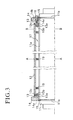
- a cylindrical drum 12 is externally inserted in a shaft 11attached with a key 11a extending along a general line of an outer peripheral surface, and a pair of drum support flanges 13 for externally fitting the drum 12 and a pair of tightening flanges 14 for tightening the drum 12 to the key-attached shaft 11 together with the drum support flanges 13 are externally fitted to opposite ends of the key-attached shaft 11.
- the drum support flange 13 and the tightening flange 14 each have a shaft insertion hole of a mutually equal diameter and key grooves 13a, 14a formed in inner peripheral edge portions of the shaft insertion holes and engaged with the key 11a of the key-attached shaft 11.
- the key grooves 13a, 14a are engaged with the key 11a and in that condition, the drum 12 is externally inserted in the key-attached shaft 11, thereby unrotatably assembling the drum support flange 13 and the tightening flange 14 to the key-attached shaft 11.
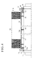
- the drum 12 is externally inserted in the key-attached shaft 11 through an annular space such that the drum 12 is spaced apart from the outer peripheral surface of the key-attached shaft 11 and from the key 11a. Opposite ends of the drum 12 are externally fitted to the drum support flanges 13. By doing so, the key-attached shaft 11 and the drum 12 are assembled on a same axis.
- the drum 12 is externally inserted in the key-attached shaft 11 such that the inner peripheral surface of the drum 12 contacts a top surface of the key 11a.
- the opposite ends of the drum 12 are externally fitted to the drum support flanges 13.
- the drum support flange 13 has a fitting portion 12b for allowing external fitting of the opposite ends of the drum 12 and a drum abutment portion 13c for abutting with opposite end faces of the drum 12 which is fitted to the drum fitting portion 13b.
- the opposite ends of the drum 12 are externally fitted to the drum fitting portion 13b. In that condition, the opposite end faces of the drum 12 are abutted with the drum abutment portion 13c.
- Each tightening flange 14 is arranged at the outside of the drum support flange 13 and abutted with a stop ring 15 arranged at the outside of the tightening flange 14 so as to prevent escape from the key-attached shaft 11.
- stop rings 15 are fitted into the annular grooves 11b formed in the opposite ends of the key-attached shaft 11 and the stop rings 15 are abutted with the peripheral edge portions of the shaft insertion holes formed in the outer surfaces of the tightening flanges 14, so that the flanges 14 are prevented from escaping and so that the drum 12 is prevented from escaping from the drum support flanges 13.
- a cut-out annular groove 14c is formed in a shaft insertion hole formed in an outer surface of each tightening flange 14, and the stop ring 15 is fitted into the cut-out annular groove 14c.
- the stop ring 15 has a radially two-split structure.
- the split ring elements are fitted into the annular groove 11b of the key-attached shaft 11 in a radially direction of the groove 11b and assembled into a circular configuration, so that the radial movement is prevented by the groove 11b.
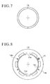
- the drum support flange 13 comprises a small diameter ring with a key groove 13a, and a large diameter ring with a key groove 13a which is in coincidence with the key groove 13a of the small diameter groove.
- the small and large rings are separately formed and coaxially welded as a single part.
- the drum fitting portion is formed by the small diameter ring and the drum abutment portion 13c is formed by the large diameter ring.
- the drum support flange is formed into a single part by cutting the drum fitting portion 13b and the drum abutment portion 13c.
- notches 13d are formed in an outer peripheral surface of the small diameter ring at an equal interval and the small diameter ring is welded to the large diameter ring within the notches 13d, so that the padding of the welded portions 10' does not interfere with the opposite ends of the drum 12.
- One of the tightening flanges 14 is provided with a plurality of internally threaded through holes 14 extending from an outer surface to an inner surface thereof and spacedly circumferentially arranged.
- a tightening bolt 16 is inserted into each through hole 14 from the outer surface side thereof and threadingly engaged therewith. While threadingly advancing the tightening bolts 16, front end faces of the bolts 16 spacedly press an outer surface of the drum support flange 13, i.e., outer surface of the drum abutment portion 13c in the circumferential direction.
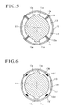
- Through holes 12a each consisting of the internally threaded hole extending from an outer peripheral surface to an inner peripheral surface of an outer peripheral wall of the drum 12 are circumferentially and axially spacedly arranged.
- a support pin 19 consisting of an externally threaded pin is inserted into each through hole 12a from the outer peripheral surface side and threadingly engaged therewith. While threadingly advancing, the front end face of the support pin 19 is abutted with the outer peripheral surface of the key-attached shaft 11 so that the drum 12 is retained between the drum support flanges 13, thereby preventing the bending of the drum 12.
- the support pin 19 is threadingly engaged with the drum 12 such that the basal end of the pin 19 is not projected from the outer peripheral surface of the drum 12.
- the channel type brush 7 is tightly spirally wound around the drum 12 thus constructed, thereby forming a rotary roll brush 18.
- the coil brush 9 is externally inserted in the outer peripheral surface of the drum 12, thereby forming the rotary brush 18. Any of them has the channel type brush 7 wound around the outer peripheral surface of the drum 12.
- the tightening bolt 16 of the tightening flange 14 is released from the ring 15 to remove the stop ring 15 from the annular groove 11b and to remove the tightening flange 14 and the support flange 13, and then, while guiding the key 11a through the shaft insertion hole, the key grooved disc type brush is inserted in the key-attached shaft 11, thereby forming the rotary roll brush 18.
- an expensive key-attached shaft for forming a disc type rotary roll brush can be utilized as a shaft of a channel type roll brush and an inexpensive rotary roll brush can be provided.
- the present invention can easily cope with difference in diameter between the shaft for the disc type rotary roll brush and the shaft for the channel type rotary roll brush.
- the same key-attached shaft can be utilized both for the channel type rotary roll brush and the disc type rotary roll brush and thus, economic efficiency can be obtained.
- the drum and the key-attached shaft can easily be centered and externally inserted.
Landscapes
- Engineering & Computer Science (AREA)
- Mechanical Engineering (AREA)
- Brushes (AREA)
Applications Claiming Priority (2)
| Application Number | Priority Date | Filing Date | Title |
|---|---|---|---|
| JP2001242938A JP3532891B2 (ja) | 2001-08-09 | 2001-08-09 | 回転ロールブラシ |
| JP2001242938 | 2001-08-09 |
Publications (2)
| Publication Number | Publication Date |
|---|---|
| EP1285729A2 true EP1285729A2 (de) | 2003-02-26 |
| EP1285729A3 EP1285729A3 (de) | 2003-10-15 |
Family
ID=19073131
Family Applications (1)
| Application Number | Title | Priority Date | Filing Date |
|---|---|---|---|
| EP02255454A Withdrawn EP1285729A3 (de) | 2001-08-09 | 2002-08-05 | Rotierende Rollenbürste |
Country Status (2)
| Country | Link |
|---|---|
| EP (1) | EP1285729A3 (de) |
| JP (1) | JP3532891B2 (de) |
Cited By (1)
| Publication number | Priority date | Publication date | Assignee | Title |
|---|---|---|---|---|
| WO2005044515A1 (de) * | 2003-11-10 | 2005-05-19 | Gebr. Schmid Gmbh & Co. | Schleifwalze mit bezug |
Families Citing this family (2)
| Publication number | Priority date | Publication date | Assignee | Title |
|---|---|---|---|---|
| KR101772869B1 (ko) | 2017-03-29 | 2017-08-30 | 이광헌 | 표면 세척용 롤 브러시 |
| KR102120168B1 (ko) * | 2018-12-07 | 2020-06-08 | 주식회사 디엠에스 | 기판세정용 롤러브러시 조립체 및 이의 조립방법 |
Family Cites Families (4)
| Publication number | Priority date | Publication date | Assignee | Title |
|---|---|---|---|---|
| US2349643A (en) * | 1940-09-07 | 1944-05-23 | Spiral Brushes Inc | Brush construction |
| GB657749A (en) * | 1943-05-06 | 1951-09-26 | Osborn Mfg Co | Improvements in or relating to rotary brushes |
| US3056986A (en) * | 1958-07-18 | 1962-10-09 | Osborn Mfg Co | Reinforced brush construction |
| US3289234A (en) * | 1964-07-17 | 1966-12-06 | Osborn Mfg Co | Brush assembly and mounting means |
-
2001
- 2001-08-09 JP JP2001242938A patent/JP3532891B2/ja not_active Expired - Lifetime
-
2002
- 2002-08-05 EP EP02255454A patent/EP1285729A3/de not_active Withdrawn
Cited By (1)
| Publication number | Priority date | Publication date | Assignee | Title |
|---|---|---|---|---|
| WO2005044515A1 (de) * | 2003-11-10 | 2005-05-19 | Gebr. Schmid Gmbh & Co. | Schleifwalze mit bezug |
Also Published As
| Publication number | Publication date |
|---|---|
| JP3532891B2 (ja) | 2004-05-31 |
| EP1285729A3 (de) | 2003-10-15 |
| JP2003052456A (ja) | 2003-02-25 |
Similar Documents
| Publication | Publication Date | Title |
|---|---|---|
| US20050248152A1 (en) | Pressed-connection arrangement | |
| CA2058479C (en) | Stacked lamination assembly for dynamoelectric machine | |
| US5256926A (en) | Alternating-current generator with stator center lamination and method for producing the center lamination | |
| US5896970A (en) | Clutch housing | |
| US3573873A (en) | Guide and compression ring for gasket inserts | |
| US5391005A (en) | Bearing cage with depressed slot end | |
| EP2233801B1 (de) | Verfahren zur Erneuerung einer Bürstendichtungsanordnung | |
| US6058591A (en) | Clutch drum and method of manufacture | |
| US5906135A (en) | Coast clutch with power take off gear | |
| EP0642208B1 (de) | Verfahren zur herstellung eines käfigläufers für induktionsmotoren | |
| US3921272A (en) | Blower wheel and method of making the same | |
| JP3316595B2 (ja) | 電磁継手用の多極継手円板形成方法 | |
| GB2225393A (en) | Flanged bearing | |
| US4268096A (en) | Flange mount for spherical bearing | |
| US4155606A (en) | Two-part plastic comb cage | |
| US4130399A (en) | Dismantling tool | |
| US5410809A (en) | Method of making a bearing cage with depressed slot end | |
| EP0535706A1 (de) | Lamelle und Befestigungsverfahren derselben | |
| US5920981A (en) | Method of manufacturing a rotor for an electromagnetic clutch assembly | |
| US2368175A (en) | Needle roller construction | |
| GB2073339A (en) | Free-wheel coupling | |
| US6394659B1 (en) | Cages for split roller bearings | |
| JP2003052456A (ja) | 回転ロールブラシ | |
| US4236289A (en) | Apparatus and method for fabricating pulleys | |
| US4094051A (en) | Method of making sheaves |
Legal Events
| Date | Code | Title | Description |
|---|---|---|---|
| PUAI | Public reference made under article 153(3) epc to a published international application that has entered the european phase |
Free format text: ORIGINAL CODE: 0009012 |
|
| AK | Designated contracting states |
Kind code of ref document: A2 Designated state(s): AT BE BG CH CY CZ DE DK EE ES FI FR GB GR IE IT LI LU MC NL PT SE SK TR Designated state(s): AT BE BG CH CY CZ DE DK EE ES FI FR GB GR IE IT LI LU MC NL PT SE SK TR |
|
| AX | Request for extension of the european patent |
Extension state: AL LT LV MK RO SI |
|
| PUAL | Search report despatched |
Free format text: ORIGINAL CODE: 0009013 |
|
| AK | Designated contracting states |
Kind code of ref document: A3 Designated state(s): AT BE BG CH CY CZ DE DK EE ES FI FR GB GR IE IT LI LU MC NL PT SE SK TR |
|
| AX | Request for extension of the european patent |
Extension state: AL LT LV MK RO SI |
|
| 17P | Request for examination filed |
Effective date: 20040313 |
|
| AKX | Designation fees paid |
Designated state(s): DE |
|
| 17Q | First examination report despatched |
Effective date: 20040921 |
|
| GRAP | Despatch of communication of intention to grant a patent |
Free format text: ORIGINAL CODE: EPIDOSNIGR1 |
|
| STAA | Information on the status of an ep patent application or granted ep patent |
Free format text: STATUS: THE APPLICATION IS DEEMED TO BE WITHDRAWN |
|
| 18D | Application deemed to be withdrawn |
Effective date: 20070926 |