EP1285778A2 - Klemmplatte - Google Patents
Klemmplatte Download PDFInfo
- Publication number
- EP1285778A2 EP1285778A2 EP02010647A EP02010647A EP1285778A2 EP 1285778 A2 EP1285778 A2 EP 1285778A2 EP 02010647 A EP02010647 A EP 02010647A EP 02010647 A EP02010647 A EP 02010647A EP 1285778 A2 EP1285778 A2 EP 1285778A2
- Authority
- EP
- European Patent Office
- Prior art keywords
- clamping plate
- clamping
- plate according
- fastening
- plate
- Prior art date
- Legal status (The legal status is an assumption and is not a legal conclusion. Google has not performed a legal analysis and makes no representation as to the accuracy of the status listed.)
- Withdrawn
Links
Images




Classifications
-
- B—PERFORMING OPERATIONS; TRANSPORTING
- B42—BOOKBINDING; ALBUMS; FILES; SPECIAL PRINTED MATTER
- B42F—SHEETS TEMPORARILY ATTACHED TOGETHER; FILING APPLIANCES; FILE CARDS; INDEXING
- B42F9/00—Filing appliances with devices clamping file edges; Covers with clamping backs
- B42F9/001—Clip boards
Definitions
- the present invention relates to a clamping plate with a plate, a clamping device which at least in the area of an edge of the Plate is attachable, a support device and an articulated holding element connected to the carrier device Clamping function.
- Clamping plates of the type mentioned usually include an im essentially rectangular plate made of plastic or Cardboard as well as a clamping device that is designed so that it one or more sheets of paper on one surface of the plate reliably fixed. Parts of the clamping device are under mechanical tension and thus clamp the paper to the Plate surface firmly.
- Clamping plates become different from their users Used for purposes. For example, they serve as stable Writing pad or as a manuscript holder.
- the Clamping device typically in the area of a transverse edge permanently attached to the plate (e.g. by riveting).
- the Clamping device generally has a carrier device that the plate is attached, and a holding element on which the paper clamped to the plate.
- the holding element for example in the form of a bracket that is pivotable is designed, and by means of a spring under mechanical There is tension.
- the previously known clamping plates have the disadvantage that the spring of your clamping device with prolonged use gradually loses its elasticity and therefore the holding element does not can exert the desired clamping force on the paper.
- Another disadvantage is that individual elements of the Clamping device can be damaged by continuous use can, which leads in particular to the fact that the clamping plate as The whole thing becomes unusable because the plate is firmly attached to it Clamping device cannot be replaced.
- Another Disadvantage of a clamping device that is firmly connected to the plate is that, especially when using panels made of cardboard or fold it in the area of the carrier device can break, which also leads to the clamping plate becomes unusable.
- the clamping device is in the previous known clamping plates in the area of a transverse edge attached. Fixing a sheet of paper on the short side of the Clipboards can only be considered cheap, if the user who wants to edit the paper is in Transverse direction writes or draws. Often it will be necessary for the user to clamp the paper in Machined longitudinal direction. Then the unsolvable turns out Attachment of the clamping device in the area of a transverse edge as unfavorable. The user fastens the long edge of a rectangular one Piece of paper using the attached in the area of the transverse edge Clamping device, the paper protrudes over a longitudinal edge of the Clamp plate out. As a result, the user during processing the paper this continuously from the Loosen the clamping device and move it on the clamping plate, to always have a fixed desk pad.
- the present invention is therefore based on the object To provide clamping plate of the type mentioned that on the one hand has a significantly more durable clamping device and it also allows the clamp to be attached to different Positions along the edges of the plate are releasably attached can.
- the carrier device with is provided at least one receiving element, and that the Holding element for engagement in the receiving element at least one protruding element, and that at least one Fastening element for a clamped connection of the Receiving element is provided with the protruding element.
- This arrangement allows both the receiving element and the protruding element in terms of material thickness too dimension that even with frequent use of the Clamping device reduces the risk of material failure.
- This also applies to the fastener that is used for a clinging Connection of the receiving element with the protruding element provides.
- a structure of the clamping device from several individual parts also allows them to be individually separated in the event of damage exchange. This will extend the lifespan of the decisively extended clamping plate according to the invention.
- An advantageous embodiment of the subject matter of the invention provides that a first groove on an upper side of the receiving element is arranged, and that the protruding element for one positive engagement with the first groove is formed.
- the Advantageousness arises primarily from the fact that on the one hand a Groove on a top of a receiving element very simple is producible and that also through the positive engagement of the protruding element of the first groove is a simple but nevertheless reliable articulated connection of the carrier device with the holding element is realized.
- a second groove the bottom of the receiving element is arranged, and that the protruding element has a groove on its top, and that the fastener clinging to the second groove of the Receiving element and in the groove of the protruding element intervenes.
- the fastener has a has a substantially U-shaped cross section and the open Ends of the fastener are hook-shaped. This Design of the fastener allows a particular reliable and permanent attachment of the holding element to the Carrier device that is also very easy to install.
- the Carrier device with a plurality of spaced Recording elements is provided, and the holding element for the Engagement in the receiving elements a plurality of protruding Has elements using fasteners be connected to each other.
- the Clamping plate has a fastening device.
- a preferred embodiment of the Clamping plate therefore provides that the plate is along one side and substantially parallel to a longitudinal edge and one Transverse edge of a recess with a plurality of spaced Has recesses in which the clamping device can be fastened is. In this way it is achieved that the clamping plate both Describe paper used lengthways and crossways can be. Depending on this, the user can use the Clamping device either in the vicinity of the corresponding longitudinal or Mount the transverse edge.
- the plate is along one side and essentially parallel a depression with a plurality for each edge has spaced recesses in which the Clamping device can be attached. This embodiment enables the greatest possible flexibility with regard to the attachment of the Clamping device on the plate.
- the carrier device of the clamping device on one side has at least one projection with an elevation, which in a Recess is recordable.
- the snaps Clamping device in one of the recesses and ensures in this way a reliable fastening of the clamping device on the plate, which is also very easy for the user can be solved.
- the clamping plate has a suspension device. With the help of this It is possible to hang the plate on a plate, for example Hang up the wall when not in use.
- the suspension device can be pulled out. Becomes uses the clamp, the hanger can be complete are confiscated, d. H. it closes on an edge of the clamping plate on and therefore does not interfere with the user. Should the Clamping plate can not be used, the suspension device are pulled out and the clamping plate saves space on a wall be hung up.
- suspension device can be attached to the clamping device. This will make it possible Clamp plate to attach to a wall even when paper is in the clamping device is included.
- Another embodiment of the clamping plate according to the invention provides before that the carrier device at least one holding element for a Has writing instrument. This makes it possible to use a writing instrument to be kept together with the clamping plate.
- the holding element at least one has a curved element for receiving and fastening a writing instrument is provided on one side of the plate.
- the clamping plate has a clamping device 1 and a plate 2, which has a rectangular shape rounded in its corner areas.
- a plate 2 which has a rectangular shape rounded in its corner areas.
- four recesses 21 are embedded, each of which is oriented parallel to a longitudinal or transverse edge 24 and extends along the respective edge.
- a plurality of equidistant bulges 22 are provided in all depressions 21, which are provided for releasable fastening of the clamping device 1 (see FIG. 2).
- the front of the plate 2 has a smooth surface.
- the clamping device 1 has a carrier device 11 and a holding element 12, which - as shown in detail in FIG. 2 - are connected to one another.
- the clamping plate has a suspension device 13 with an elongated hole 131, which is designed for mounting the clamping plate on a wall.
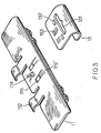
- FIG. 3 shows the undersides of the Carrier device 11 and the suspension device 13.
- the former comprises there a projection 114 between the curved elements 112 and, on both sides adjacent to the projection 114, two elongated Cutouts 115 with a web 115 '.
- 4 is for further Illustrate again the top of the hanger 13 shown.
- the spaced, rectangular ones are clearly recognizable trained elevations 132 with their openings 132 ', the also rectangular opening 133 and the elongated hole 131.
- the suspension device 13 is so at its upper end shaped so that it fits positively on the curved Adapts intermediate piece 113 of the carrier device 11.
- Your maximum deflection corresponds to the difference between the length of the rectangular opening 133 and the length of the Projection 114.
- the webs engage 115 'locking into the openings 132' of the elevations 132.
- To the Hanging the clamping plate on a wall becomes the elongated hole 131 passed through a nail or wall hook.
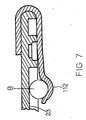
- Fig. 5 shows a cross-sectional view showing the connection of the Carrier device 11 with the holding element 12 using the U-shaped Fastener A illustrates.
- the lead A groove 121 ' is embedded in the holding element 121.
- the protrusion 121 is shaped at its front end to be at assembly in the first groove 1131 'on the top of the receiving element 1131 is recorded.
- the attachment of the Holding element 12 on the carrier device 11 takes place with the help of the U-shaped Fastening element A, which at both free ends each has a hook A1. It encompasses the projection 1131 and Clamping the projection 121, the hooks A1 in the grooves 121 ' or 1131 ". In this way, the projection 121 and the receptacle 1131 compressed, thereby creating a reliable joint-like connection between the carrier device 11 and the holding element 12 is produced.
- the clamping device 1 can be attached to one of the four sides of the plate 2.
- the projections 111 of the carrier device are first assembled 11 inserted into a recess 21, so that the elevations 111 'in the Bulges 22 are included and thus the Carrier device 11 is secured. Then one after the other Holding element 12, the suspension device 13 and the two Fastening elements A in the manner already described above and Way assembled.
Landscapes
- Sheet Holders (AREA)
- General Details Of Gearings (AREA)
- Clamps And Clips (AREA)
Abstract
Description
Die Klemmplatte weist eine Klemmvorrichtung 1 und eine Platte 2 auf, die eine rechteckige, in ihren Eckbereichen abgerundete Form besitzt. In die Rückseite der Platte 2 sind vier Vertiefungen 21 eingelassen, die jeweils parallel zu einer Längs- bzw. Querkante 24 orientiert sind und sich entlang der jeweiligen Kante erstrecken. In allen Vertiefungen 21 wird eine Mehrzahl äquidistanter Ausbuchtungen 22 zur Verfügung gestellt, die für eine lösbare Befestigung der Klemmvorrichtung 1 vorgesehen sind (s. Fig. 2). Die Vorderseite der Platte 2 hat hingegen eine glatte Oberfläche.
Die Klemmvorrichtung 1 besitzt eine Trägereinrichtung 11 und ein Halteelement 12, die - wie in Fig. 2 detailliert dargestellt - miteinander verbunden sind. Ferner weist die Klemmplatte eine Aufhängvorrichtung 13 mit einem Langloch 131 auf, die für die Montage der Klemmplatte an einer Wand ausgelegt ist.
- 1
- Klemmvorrichtung
- 2
- Platte
- 11
- Trägereinrichtung
- 12
- Halteelement
- 13
- Aufhängvorrichtung
- 21
- Vertiefung
- 22
- Ausbuchtung
- 23
- ausgesparter Bereich
- 24
- Kante
- 111
- Vorsprung
- 111'
- Erhebung
- 112
- geschwungenes Element
- 112'
- Spalt
- 113
- gebogenens Zwischenstück
- 114
- Vorsprung
- 115
- längliche Aussparung
- 115'
- Steg
- 121
- hervorstehendes Element
- 121'
- Nut
- 131
- Langloch
- 132
- Erhebung
- 132'
- Öffnung
- 133
- rechteckige Öffnung
- 1131
- Aufnahmeelement
- 1131'
- erste Nut
- 1131"
- zweite Nut
- A
- U-förmiges Befestigungselement
- A1
- Haken
- B
- Schreibgerät
Claims (15)
- Klemmplatte mit einer Platte (2), einer Klemmvorrichtung (1), die mindestens im Bereich einer Kante (24) der Platte (2) anbringbar ist, einer Trägereinrichtung (11) sowie einem gelenkig mit der Trägereinrichtung (11) verbundenen Halteelement (12) mit Klemmfunktion, dadurch gekennzeichnet, dass die Trägereinrichtung (11) mit mindestens einem Aufnahmeelement (1131) versehen ist, und dass das Haltelement (12) für den Eingriff in das Aufnahmeelement (1131) mindestens ein hervorstehendes Elemente (121) aufweist, und dass mindestens ein Befestigungselement (A) für eine klammernde Verbindung des Aufnahmeelements (1131) mit dem hervorstehenden Element (121) vorgesehen ist.
- Klemmplatte nach Anspruch 1, dadurch gekennzeichnet, dass eine erste Nut (1131') an einer Oberseite des Aufnahmeelements (1131) angeordnet ist, und dass das hervorstehende Element (121) für einen formschlüssigen Eingriff mit der ersten Nut (1131') ausgebildet ist.
- Klemmplatte nach einem der Ansprüche 1 oder 2, dadurch gekennzeichnet, dass eine zweite Nut (1131") an der Unterseite des Aufnahmeelements (1131) angeordnet ist, und dass das hervorstehende Element (121) an seiner Oberseite eine Nut (121') besitzt, und dass das Befestigungselement (A) klammernd in die zweite Nut (1131") des Aufnahmeelements (1131) und in die Nut (121') des hervorstehenden Elements (121) eingreift.
- Klemmplatte nach einem der Ansprüche 1 bis 3, dadurch gekennzeichnet, dass das Befestigungselement (A) einen im wesentlichen U-förmigen Querschnitt besitzt, und dass die offenen Enden (A1) des Befestigungselements (A) hakenförmig ausgebildet sind.
- Klemmplatte nach einem der vorhergehenden Ansprüche, dadurch gekennzeichnet, dass die Trägereinrichtung (11) mit einer Mehrzahl beabstandeter Aufnahmeelemente (1131) versehen ist und dass das Haltelement (12) für den Eingriff in die Aufnahmeelemente (1131) eine Mehrzahl hervorstehender Elemente (121) aufweist, und dass Befestigungselemente (A) für eine klammernde Verbindung des Aufnahmeelements (1131) mit dem hervorstehenden Element (121) vorgesehen sind.
- Klemmplatte nach einem der vorhergehenden Ansprüche, dadurch gekennzeichnet, dass die Klemmplatte eine Befestigungseinrichtung für die Klemmvorrichtung aufweist.
- Klemmplatte nach Anspruch 6, dadurch gekennzeichnet, dass die Platte (2) auf einer Seite entlang und im wesentlichen parallel zu einer Längskante und einer Querkante eine Vertiefung (21) mit einer Mehrzahl beabstandeter Aussparungen (22) aufweist, in denen die Klemmvorrichtung (1) befestigbar ist.
- Klemmplatte nach einem der Ansprüche 6 oder 7, dadurch gekennzeichnet, dass die Platte (2) auf einer Seite entlang und im wesentlichen parallel zu allen Kanten jeweils eine Vertiefung (21) mit einer Mehrzahl beabstandeter Aussparungen (22) aufweist, in denen die Klemmvorrichtung (1) befestigbar ist.
- Klemmplatte nach einem der Ansprüche 6 bis 8, dadurch gekennzeichnet, dass die Trägereinrichtung (11) der Klemmvorrichtung (1) auf einer Seite mindestens einen Vorsprung (111) mit einer Erhebung (111') aufweist, die in einer Aussparung (22) aufnehmbar ist.
- Klemmplatte nach einem der vorhergehenden Ansprüche, dadurch gekennzeichnet, dass die Klemmplatte eine Aufhängvorrichtung (13) aufweist.
- Klemmplatte nach Anspruch 10, dadurch gekennzeichnet, dass die Aufhängvorrichtung (13) ausziehbar ist.
- Klemmplatte nach einem der Ansprüche 10 oder 11, dadurch gekennzeichnet, dass die Aufhängvorrichtung (13) an der Klemmvorrichtung (1) anbringbar ist.
- Klemmplatte nach einem der vorhergehenden Ansprüche, dadurch gekennzeichnet, dass die Trägereinrichtung (11) mindestens ein Halteelement für ein Schreibgerät (B) aufweist.
- Klemmplatte nach Anspruch 13, dadurch gekennzeichnet, dass das Halteelement mindestens ein geschwungenes Element (112) aufweist, das zur Aufnahme und Befestigung eines Schreibgeräts (B) an einer Seite der Platte vorgesehen ist.
- Klemmplatte nach Anspruch 13 oder 14, dadurch gekennzeichnet, dass das geschwungene Element (112) integral mit und vom selben Material wie die Trägereinrichtung (11) gebildet ist.
Applications Claiming Priority (2)
| Application Number | Priority Date | Filing Date | Title |
|---|---|---|---|
| US925480 | 1978-07-17 | ||
| US09/925,480 US6386589B1 (en) | 2001-08-10 | 2001-08-10 | Clipboard |
Publications (2)
| Publication Number | Publication Date |
|---|---|
| EP1285778A2 true EP1285778A2 (de) | 2003-02-26 |
| EP1285778A3 EP1285778A3 (de) | 2004-02-04 |
Family
ID=25451792
Family Applications (1)
| Application Number | Title | Priority Date | Filing Date |
|---|---|---|---|
| EP02010647A Withdrawn EP1285778A3 (de) | 2001-08-10 | 2002-05-11 | Klemmplatte |
Country Status (2)
| Country | Link |
|---|---|
| US (1) | US6386589B1 (de) |
| EP (1) | EP1285778A3 (de) |
Families Citing this family (9)
| Publication number | Priority date | Publication date | Assignee | Title |
|---|---|---|---|---|
| US6173955B1 (en) * | 1998-12-22 | 2001-01-16 | Mikohn Gaming Corporation | Poker dice casino game method of play |
| US6883769B2 (en) * | 2003-07-10 | 2005-04-26 | Ellis N. Shamoon | Clipboard |
| US6971616B1 (en) | 2003-09-22 | 2005-12-06 | Lake Gary F | Clipboard |
| US6905104B1 (en) | 2004-03-03 | 2005-06-14 | Keith Offenhauer | Patient or visitor sign-in device |
| US7445246B1 (en) | 2007-11-27 | 2008-11-04 | Gary Plastic Packaging Corp. | Clipboard assembly |
| US20120091308A1 (en) | 2010-10-14 | 2012-04-19 | Small Larue D | LaRue's two-clip double sided clipboard |
| CN106739634A (zh) * | 2017-03-13 | 2017-05-31 | 乔赫扬 | 教育管理用文件夹 |
| WO2019246178A1 (en) * | 2018-06-20 | 2019-12-26 | Tracer Imaging Llc | System and method for applying an image to a substrate to form a display article |
| USD892214S1 (en) * | 2018-07-02 | 2020-08-04 | Robert Jordan | Chalk holder |
Family Cites Families (7)
| Publication number | Priority date | Publication date | Assignee | Title |
|---|---|---|---|---|
| US3638282A (en) * | 1971-01-13 | 1972-02-01 | Mattel Inc | Paper holddown clip |
| US4243249A (en) * | 1978-04-20 | 1981-01-06 | Goss H Calvin | Document holder assembly |
| DE8704616U1 (de) * | 1987-03-28 | 1987-07-09 | IMCO J. Michaelis GmbH & Co KG, 7000 Stuttgart | Durch eine Klammer zusammengehaltener Stapel aus übereinanderliegenden, flächenartigen Gegenständen |
| US4948172A (en) * | 1989-01-17 | 1990-08-14 | Chang Shih Ho | Combined clip board and pen holder |
| US5046760A (en) * | 1989-12-18 | 1991-09-10 | Krepp Charles M | General purpose clipboard |
| US5897934A (en) * | 1997-07-16 | 1999-04-27 | Yeh; Morgen | Writing/reading panel with hidden indication bar |
| CA2315292A1 (en) * | 2000-08-04 | 2002-02-04 | Ching Tsung Tsai | Collapsible clipboard |
-
2001
- 2001-08-10 US US09/925,480 patent/US6386589B1/en not_active Expired - Fee Related
-
2002
- 2002-05-11 EP EP02010647A patent/EP1285778A3/de not_active Withdrawn
Also Published As
| Publication number | Publication date |
|---|---|
| EP1285778A3 (de) | 2004-02-04 |
| US6386589B1 (en) | 2002-05-14 |
Similar Documents
| Publication | Publication Date | Title |
|---|---|---|
| DE3425827C1 (de) | Heftmechanik zum Abheften von gelochtem Schriftgut | |
| DE3410974A1 (de) | Deckenbefestigung fuer dekorationselemente und dergleichen | |
| DE202009002242U1 (de) | Eckverbindung | |
| EP1285778A2 (de) | Klemmplatte | |
| AT4818U1 (de) | Bilderrahmen | |
| DE202018106711U1 (de) | Profilsystem | |
| DE3245056A1 (de) | Elastische klemme | |
| DE69630205T2 (de) | Bildhalter | |
| WO2004111471A1 (de) | Hochlastverbindungselement für wände | |
| DE102011010828A1 (de) | Klemmvorrichtung zur lösbaren Befestigung eines Gerätegehäuses an einer Profilschiene | |
| DE202018001757U1 (de) | Snap-Befestigungselement | |
| DE102017124413B4 (de) | Bohrschablone und Verfahren zum Markieren oder Anbohren zweier Möbelplatten | |
| AT409977B (de) | Entwässerungskasten für eine papiermaschine | |
| DE3603876C2 (de) | ||
| EP2128046A1 (de) | Befestigungselement für eine Rollenleiste und Durchlaufregal | |
| DE202008005295U1 (de) | Verbindung | |
| EP0947766A2 (de) | Feuchtraumleuchte | |
| DE19709720C2 (de) | Befestigungsvorrichtung für eine Papierhaltemechanik eines Aktenordners | |
| DE3109561C2 (de) | Wechselbildhalterung | |
| DE102004057705A1 (de) | Klemmvorrichtung zur lösbaren Befestigung eines Gerätegehäuses an einer Profilschiene | |
| DE8002883U1 (de) | Kunststoff-Clip zur Befestigung von Verkleidungen in Kraftfahrzeugen o.dgl | |
| DE2704023A1 (de) | Schreib- und zeichenplatte | |
| DE8806432U1 (de) | Klemmrahmen | |
| DE202024104825U1 (de) | Befestigungsanordnung zwischen einem Halter und einer Kabeltragkomponente sowie Halter mit einem daran angeschlossenen Anschlussadapter | |
| DE8606422U1 (de) | Wandbefestigungselement für Flächen- und Kompaktheizkörper |
Legal Events
| Date | Code | Title | Description |
|---|---|---|---|
| PUAI | Public reference made under article 153(3) epc to a published international application that has entered the european phase |
Free format text: ORIGINAL CODE: 0009012 |
|
| AK | Designated contracting states |
Kind code of ref document: A2 Designated state(s): AT BE CH CY DE DK ES FI FR GB GR IE IT LI LU MC NL PT SE TR Designated state(s): AT BE CH CY DE DK ES FI FR GB GR IE IT LI LU MC NL PT SE TR |
|
| AX | Request for extension of the european patent |
Extension state: AL LT LV MK RO SI |
|
| PUAL | Search report despatched |
Free format text: ORIGINAL CODE: 0009013 |
|
| AK | Designated contracting states |
Kind code of ref document: A3 Designated state(s): AT BE CH CY DE DK ES FI FR GB GR IE IT LI LU MC NL PT SE TR |
|
| AX | Request for extension of the european patent |
Extension state: AL LT LV MK RO SI |
|
| 17P | Request for examination filed |
Effective date: 20040306 |
|
| AKX | Designation fees paid |
Designated state(s): AT BE CH CY DE DK ES FI FR GB GR IE IT LI LU MC NL PT SE TR |
|
| STAA | Information on the status of an ep patent application or granted ep patent |
Free format text: STATUS: THE APPLICATION IS DEEMED TO BE WITHDRAWN |
|
| 18D | Application deemed to be withdrawn |
Effective date: 20071201 |