EP1285798B1 - Toit de véhicule à déflecteur - Google Patents
Toit de véhicule à déflecteur Download PDFInfo
- Publication number
- EP1285798B1 EP1285798B1 EP20020018463 EP02018463A EP1285798B1 EP 1285798 B1 EP1285798 B1 EP 1285798B1 EP 20020018463 EP20020018463 EP 20020018463 EP 02018463 A EP02018463 A EP 02018463A EP 1285798 B1 EP1285798 B1 EP 1285798B1
- Authority
- EP
- European Patent Office
- Prior art keywords
- panel
- vehicle roof
- lifting
- roof according
- lid
- Prior art date
- Legal status (The legal status is an assumption and is not a legal conclusion. Google has not performed a legal analysis and makes no representation as to the accuracy of the status listed.)
- Expired - Lifetime
Links
Images




Classifications
-
- B—PERFORMING OPERATIONS; TRANSPORTING
- B60—VEHICLES IN GENERAL
- B60J—WINDOWS, WINDSCREENS, NON-FIXED ROOFS, DOORS, OR SIMILAR DEVICES FOR VEHICLES; REMOVABLE EXTERNAL PROTECTIVE COVERINGS SPECIALLY ADAPTED FOR VEHICLES
- B60J7/00—Non-fixed roofs; Roofs with movable panels, e.g. rotary sunroofs
- B60J7/02—Non-fixed roofs; Roofs with movable panels, e.g. rotary sunroofs of sliding type, e.g. comprising guide shoes
- B60J7/04—Non-fixed roofs; Roofs with movable panels, e.g. rotary sunroofs of sliding type, e.g. comprising guide shoes with rigid plate-like element or elements, e.g. open roofs with harmonica-type folding rigid panels
- B60J7/043—Sunroofs e.g. sliding above the roof
- B60J7/0435—Sunroofs e.g. sliding above the roof pivoting upwardly to vent mode and moving at the outside of the roof to fully open mode
Definitions
- the invention relates to a vehicle roof with at least one cover which can be exposed and displaced on its trailing edge and with a control mechanism for the cover, which has a rear lifting and displacing mechanism which is hinged near the trailing edge of the cover and comprises at least one control carriage connected to the cover. which is displaceably guided in lateral guide rails and driven.
- a vehicle roof with at least one lid is known, which can be raised to open by means of a release lever at its rear edge and then slid above the fixed vehicle roof.
- the displacement movement takes place by means of a first drive cable and the deployment movement takes place by means of a second drive cable movable in opposite directions to this.
- a deployment lever controlling the deployment lever is in constant engagement with the one drive cable via a rear carriage while a carriage near the leading edge, which is responsible for the sliding movement of the cover, is in constant engagement with the other drive cable movable in opposition thereto. Due to this constant coupling, complete separation of the deployment movement from the displacement movement is only possible to a limited extent, and only a relatively short travel path of the drive cable is available for the deployment movement.
- a disadvantage of the known roofs is that the lid is held in its closed position only on the deployment lever and a sliding carriage in the guide rail. If the vehicle equipped with such a roof is operated at high speed, the displaceable cover is pulled upwards at its trailing edge due to the negative pressure caused by the air flow passing over the vehicle, which may eventually lead to the cover being displaced from the roof frame lifted seal is lifted. The resulting gap noise is caused, which are perceived by the vehicle occupants as disturbing.
- the invention has for its object to provide a vehicle roof of the aforementioned type, the rear adjustment and lifting mechanism has increased stability in the lid closing position.
- engagement elements ensures that in the closed position of the lid, the lid and in particular the rear edge is securely locked with the roof-mounted engagement elements and is not pulled up even when strong forces acting on the rear Dekkel Scheme , In this way, a lifting of the cover of the seal provided on the roof frame and thus the emergence disturbing wind noise are excluded.
- the roof-fixed part may comprise a locking link into which engages the engagement element provided on the movable part of the lifting and shifting mechanism when the cover is closed.
- the engagement element may be formed on the movable part of the lifting and displacing mechanism as a laterally projecting locking angle, wherein at least the laterally projecting part of the blocking angle is preferably provided with a sliding element.
- the engagement elements may also be designed so that they counteract in the closed position of the lid expressions of the lid also down
- the stability of the closed vehicle roof can be further increased if a movable part of the lifting and shifting mechanism and a part connected to the cover in each case in the closed position of the lid have effective locking elements which oppose an expression of the lid upwards. Due to the double locking of the lid, on the one hand by means of the engagement elements and on the other hand by means of the locking elements, it is ensured that the lid even at a high directed against the inside of the lid pressure, as it could be caused in the event of a crash by the impact of a vehicle occupant against the lid bottom , can not be pushed up out of the roof opening.
- the movable part of the lifting and displacing mechanism may in turn be a deployment lever, preferably the same deployment lever, on which the engagement element associated with the movable part of the lifting and shifting mechanism is provided.
- the part connected to the lid can in this case be formed by a cover guide, which is in engagement with a part of the lifting and displacing mechanism and which allows a relative movement of the latter relative to the cover when it is exposed.
- the locking elements may be formed, for example, as downwardly bent or as laterally and upwardly projecting locking tabs.
- the presently explained vehicle roof is preferably used in such a vehicle, in which the cover above the fixed vehicle roof is displaced to the rear.
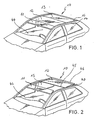
- a vehicle roof 10 (see Fig. 1) comprises a above a windshield 44 pivotally mounted Windabweiserlamelle 11, behind this Windabweiserlamelle 11 lying sliding cover 12 and adjoining the closed lid 12 solid roof panel 13.
- the side Windabweiserlamelle 11, the lid 12 and the roof panel 13 each bounded by a side rail 14.
- the vehicle roof 10 has a completely smooth-surfaced appearance.
- the cover 12 is slidable rearwardly over the fixed vehicle roof 10 to release a roof opening 15 (see FIG 2), no guides arranged above the fixed vehicle roof 10 are required for this purpose.
- the cover 12 is rather supported by means of laterally hinged in the region of the trailing edge 46 of the lid 12 supporting lever 40, which are movable in below the level of the fixed roof skin guides and which on exit up a flexible sealing element 16 partially displacing, which is arranged between the side rails 14 and the components 11, 12 and 13.
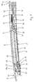
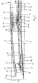
- the necessary for the issuing and moving the lid 12 mechanism is similar to the left and right side of the lid 12, so that only the mechanics of one side described and described below with reference to FIG. 3 to 14 will be explained.
- the opening and shifting mechanism for the cover 12 comprises a guide rail 17, which is formed as a profile part with longitudinally extending guideways.
- a front control slide 18 and a rear control slide 19 are guided longitudinally displaceable.
- the two control slides 18 and 19 are fixedly connected at a mutual distance with a drive cable 21.
- the control slides 18 and 19 are also connected to the front edge 45 and the trailing edge 46 of the lid 12, namely respectively via a slide guide or support lever for lifting and carrying the front edge 45 and the trailing edge 46 of the lid 12 in its adjustment between its closed and its open position, as in the following first for the leading edge 45 and then for the trailing edge 46 of the lid 12th will be explained in detail.
- a lateral vertical cover carrier 22 is arranged on the underside of the lid 12 in the region of the front edge 45 thereof.
- a laterally projecting slide pin 23 is fixedly mounted at a distance from the front edge 45 of the lid 12.
- the slide pin 23 engages in a slide track 24a a lifting link 24 which is fixedly mounted on the front control slide 18 or integrally formed therewith.
- the slide track 24a of the lift gate 24 has a rising from its rear end to its front end in the region of the front edge 45 of the lid 12 course.
- the slide track 24a is formed into an approximately L-shape with a front short bent leg portion and a rear long bent leg portion.
- the sliding pin 23 When the cover 12 is closed, the sliding pin 23 is located in the region of the rear end of the slide track 24a (FIG. 4) and the cover 12 is raised at the front and during the displacement of the cover 12 at the front elevated end of the slide track 24a (see, for example, FIG.
- the slide pin 23 moves in the slide track 24a due to a longitudinal displacement of the control carriage 18 caused by the drive cable 21, wherein the slide pin 23 from its in FIG. 3 with the lid 12 closed, by a rearward displacement of the front control carriage 18 to its upper position, in which the front edge 45 of the lid 12 is raised (see FIG. 7).
- the guide rail 17 further comprises a guide track 26 for the Sliding pin 25 which extends parallel to the carriage guide track 20 in the longitudinal direction of the guide rail 17.
- a link 27 for guiding the front edge 45 of the lid 12 in its raising and lowering movement.
- This gate 27 is fixedly connected to the guide rail 17 and the vehicle roof 10 and has a slide track 28, which adjoins the front end of the sliding pin guide track 26 of the guide rail 17 and extends downwards towards the front.
- the sliding pin 25 (see Figures 3 and 4) is located at the lower end of the slide track 28.
- the sliding pin 25 is largely free of play in the vehicle longitudinal direction (x-direction) and thus determines the exact position of the front edge 45 in the Closed position of the lid 12th
- the exact position of the front edge 45 in the vertical direction is determined by the slide pin 23 which is received in the rear portion of the slide track 24a in the vertical direction substantially free of play.
- the front edge 45 of the lid 12 is raised by means of the Hubkulisse 24 and the sliding pin 23 by backward process of the front control carriage 18, simultaneously moves the sliding pin 25 along the rearwardly rising slide track 28 upwards and finally enters the front end of the sliding pin Guideway 26 of the guide rail 17 (see FIG 7).
- the cover 12 has assumed a position in the region of its front edge 45, from which it can be moved to the rear.
- the cover 12 has, in the region of its trailing edge 46, a lid carrier 30 which extends downwards (see FIG.
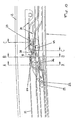
- a deployment lever 31 To raise the rear edge or the trailing edge 46 of the lid 12 is a deployment lever 31, the at his The front end is pivotably hinged to the rear steering slide r19 by means of a bearing pin 32 (see Fig. 10) and has a laterally projecting rear slider 33 at its rear end. With the lid closed (FIG. 3), the rear slider 33 engages up to a raised lid position or transfer position (FIG. 7) in a lid guide 34 on the lid carrier 30 which is open towards the rear (see, for example, FIG.
- a slide track 37 of the lifting link 36 extends from the front to the back initially rising, then substantially parallel to the longitudinal direction of the guide rail 17 and then sloping and opening into a guide track 38 of the guide rail 17, which may coincide with the carriage guide track 20.
- a support lever 40 for the trailing edge 46 of the lid 12 is hinged to the lid carrier 30.
- On the bearing pin 39 opposite end of the support lever 40 projects from this laterally a guide pin 41 which is guided in all positions of the trailing edge 46 of the lid 12 in a guide pin track 42 with respect to the former inner guide rail 17 outer guide rail 47.
- the guide pin track 42 extends in the longitudinal direction of the guide rail 47. Instead of the inner guide rail 17 and the outer guide rail 47, only one guide rail may be provided, which contains the said guideways.
- a support pin 43 (see Figure 5), which only after complete lifting of the trailing edge 46 of the lid 12 enters the guide pin track 42 and further movement the lid 12 slides backwards in this guide pin track 42 to support the lid pivoted up on the rear side together with the guide pin 41 guided in the guide pin track 42 instead of the opening lever 31.
- the closing movement of the lid 12 takes place in a coupled coupled forward movement of the two control slides 18 and 19 with a reverse sequence of the pivoting movements of the trailing edge 46 and the front edge 45 of the cover 12th
- engaging elements and preferably locking elements are provided to stabilize the lid in its closed position.
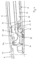
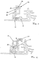
- an upwardly open cam slot 50 is provided on the top of the roof fixed Hubkulisse 36 which is in the lid closing position in engagement with an engaging member 52 which is provided in the upper region of the deployment lever 31.
- the engagement element 52 comprises a laterally projecting locking angle 54, which has a sliding element 56 on its upper end region protruding to the side, which is retracted into the sliding slot 50 in the closed position of the cover and fixes the cover 12 in a roof-fixed manner.
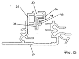
- FIG. Vehicle roof 10 shown locking elements, one of which is designed as a locking tab 48 and the other as a locking angle 49, as shown in FIG. 13 is shown.
- the locking tab 48 is formed on the cover guide 34 as a downwardly facing web in the front region thereof.
- the locking angle 49 protrudes sideways from the deployment lever 31 and engages in the closed position of the lid 12 as shown in FIG. 10, the locking tab 48.
- the rear slider 33 can be at a very strong pressure on the Inside the lid 12 are not rotated about its longitudinal axis from the cover guide 34 or torn out. In the closed position of the lid 12 thus a secure locking of the lid 12 is ensured via the release lever 31 with the guide rail 17 and thus with the fixed vehicle roof 10.
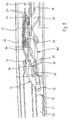
- FIG. 14 a transitional position is shown in which both the engagement members 50 and 52 and the locking members 48 and 49 are about to unlock. It is understood that the arrangement can also be made so that the locking and unlocking of the engagement elements 50 and 52 does not occur simultaneously with the locking or unlocking of the locking elements 48 and 49, but offset.
Landscapes
- Engineering & Computer Science (AREA)
- Mechanical Engineering (AREA)
- Fittings On The Vehicle Exterior For Carrying Loads, And Devices For Holding Or Mounting Articles (AREA)
- Body Structure For Vehicles (AREA)
- Lock And Its Accessories (AREA)
Claims (15)
- Toit de véhicule comprenant au moins un capot (12) coulissant et déployable sur son bord postérieur (46), et un mécanisme de commande du capot (12), présentant un mécanisme postérieur (19, 31) de levage et de coulissement qui est articulé sur ledit capot (12) à proximité du bord postérieur (46) de ce dernier, et englobe au moins un chariot de commande (19) relié audit capot (12), et pouvant être entraîné et guidé à coulissement dans des glissières latérales de guidage (17),
caractérisé par le fait
qu'une pièce mobile (31) du mécanisme de levage et de coulissement, et une pièce (36) faisant corps avec le pavillon, comportent des éléments (50, 52) de venue en prise qui sont opérants dans la position fermée du capot (12), et s'opposent à une expulsion dudit capot (12) vers le haut. - Toit de véhicule, selon la revendication 1,
caractérisé par le fait que la pièce mobile du mécanisme (19, 31) de levage et de coulissement est matérialisée par un levier de déploiement (31). - Toit de véhicule, selon la revendication 1 ou 2,
caractérisé par le fait que la pièce (36) faisant corps avec le pavillon englobe une coulisse de verrouillage (50) dans laquelle l'élément (52) de venue en prise, prévu sur la pièce mobile (31) du mécanisme de levage et de coulissement, pénètre au stade de la fermeture du capot (12). - Toit de véhicule, selon l'une des revendications précédentes,
caractérisé par le fait que l'élément (52) de venue en prise, situé sur la pièce mobile (31) du mécanisme de levage et de coulissement, est réalisé sous la forme d'une cornière de blocage (54) saillant latéralement. - Toit de véhicule, selon la revendication 4,
caractérisé par le fait qu'au moins la partie de la cornière de blocage (54), qui fait saillie latéralement, est pourvue d'un élément glissant (56). - Toit de véhicule, selon l'une des revendications précédentes,
caractérisé par le fait que, dans la position fermée du capot (12), les éléments (50, 52) de venue en prise s'opposent à une expulsion dudit capot (12) vers le bas. - Toit de véhicule, selon l'une des revendications précédentes,
caractérisé par le fait qu'une pièce mobile (31) du mécanisme (19, 31) de levage et de coulissement, et une pièce (22, 34) reliée au capot (12), comportent des éléments de verrouillage (48, respectivement 49) qui sont respectivement opérants dans la position fermée du capot (12), et s'opposent à une expulsion dudit capot (12) vers le haut. - Toit de véhicule, selon la revendication 7,
caractérisé par le fait que la pièce mobile du mécanisme (19, 31) de levage et de coulissement est matérialisée par un levier de déploiement (31). - Toit de véhicule, selon la revendication 7,
caractérisé par le fait que l'élément (52) de venue en prise prévu sur une pièce mobile du mécanisme (19, 31) de levage et de coulissement, et l'élément de verrouillage (49) prévu sur une pièce mobile dudit mécanisme de levage et de coulissement, sont prévus sur un seul et même levier de déploiement (31). - Toit de véhicule, selon l'une des revendications 7 à 9,
caractérisé par le fait que la pièce reliée au capot (12) est matérialisée par un guide (34) dudit capot qui est en prise avec une pièce (33) du mécanisme (19, 31) de levage et de coulissement et autorise, au stade du déploiement, un mouvement relatif de ladite pièce vis-à-vis dudit capot (12). - Toit de véhicule, selon l'une des revendications 7 à 10,
caractérisé par le fait que l'élément de verrouillage, situé sur la pièce (34) reliée au capot (12), est réalisé sous la forme d'une patte de verrouillage (49) coudée vers le bas. - Toit de véhicule, selon l'une des revendications 7 à 11,
caractérisé par le fait que l'élément de verrouillage, situé sur la pièce mobile (31) du mécanisme de levage et de coulissement, est réalisé sous la forme d'une cornière de verrouillage (49) saillant latéralement et vers le haut. - Toit de véhicule, selon l'une des revendications précédentes,
caractérisé par le fait que le capot (12) peut coulisser vers l'arrière au-dessus dudit toit fixe (10) du véhicule. - Toit de véhicule, selon l'une des revendications précédentes,
caractérisé par le fait que le mécanisme de levage et de coulissement englobe un levier de déploiement (31) qui est articulé à pivotement sur un chariot postérieur de commande (19) ; est relevé par une coulisse de levage (36) faisant corps avec le pavillon, lors d'un mouvement rétrograde dudit chariot postérieur de commande (19), en vue de soulever le bord postérieur (46) du capot (12) ; et supprime alors l'engagement actif des éléments de venue en prise, ainsi que des éléments de verrouillage (48, 49). - Toit de véhicule, selon la revendication 14,
caractérisé par le fait que, après la suppression de l'engagement actif des éléments de venue en prise, ainsi que des éléments de verrouillage (48, 49), le levier de déploiement (31) est désengage d'avec le capot (12) et délègue alors, à un levier d'appui (40) distinct l'appui du bord postérieur (46) dudit capot (12).
Applications Claiming Priority (2)
| Application Number | Priority Date | Filing Date | Title |
|---|---|---|---|
| DE2001140389 DE10140389C2 (de) | 2001-08-23 | 2001-08-23 | Fahrzeugdach |
| DE10140389 | 2001-08-23 |
Publications (2)
| Publication Number | Publication Date |
|---|---|
| EP1285798A1 EP1285798A1 (fr) | 2003-02-26 |
| EP1285798B1 true EP1285798B1 (fr) | 2006-05-24 |
Family
ID=7695765
Family Applications (1)
| Application Number | Title | Priority Date | Filing Date |
|---|---|---|---|
| EP20020018463 Expired - Lifetime EP1285798B1 (fr) | 2001-08-23 | 2002-08-16 | Toit de véhicule à déflecteur |
Country Status (3)
| Country | Link |
|---|---|
| EP (1) | EP1285798B1 (fr) |
| JP (1) | JP2003072378A (fr) |
| DE (2) | DE10140389C2 (fr) |
Families Citing this family (6)
| Publication number | Priority date | Publication date | Assignee | Title |
|---|---|---|---|---|
| DE10329536B4 (de) | 2003-06-30 | 2007-07-19 | Webasto Ag | Fahrzeugdach |
| DE102006060019B4 (de) * | 2006-12-19 | 2009-01-08 | Webasto Ag | Fahrzeugdach |
| DE102008024948B4 (de) * | 2008-05-23 | 2010-04-08 | Webasto Ag | Bauraumoptimierte Antriebsmechanik für Deckelelement |
| DE202010012974U1 (de) * | 2010-11-24 | 2012-02-27 | Inalfa Roof Systems Group B.V. | Offendachkonstruktion für ein Fahrzeug |
| EP2727755B1 (fr) * | 2012-10-30 | 2015-10-21 | Inalfa Roof Systems Group B.V. | Construction décapotable pour véhicule |
| DE102019104981A1 (de) * | 2019-02-27 | 2020-08-27 | Webasto SE | Öffnungsfähiges Fahrzeugdach mit einem Deckel |
Family Cites Families (7)
| Publication number | Priority date | Publication date | Assignee | Title |
|---|---|---|---|---|
| DE8229121U1 (de) * | 1982-10-16 | 1985-08-22 | Webasto-Werk W. Baier GmbH & Co, 8035 Gauting | Schiebedach für Fahrzeuge |
| NL9001686A (nl) * | 1990-07-25 | 1992-02-17 | Vermeulen Hollandia Octrooien | Dakpaneelsamenstel voor een motorvoertuig. |
| IT1261560B (it) * | 1993-08-11 | 1996-05-23 | Dispositivo per l'apertura e la chiusura di un tettuccio di automobile | |
| DE9410631U1 (de) * | 1994-07-01 | 1995-11-02 | Farmont, Rolf, Dr., 40474 Düsseldorf | Schiebedach |
| DE19713348C1 (de) * | 1997-03-29 | 1998-07-09 | Webasto Karosseriesysteme | Fahrzeugdach mit wenigstens einem an seiner Hinterkante anhebbaren und oberhalb des festen Fahrzeugdachs verschiebbaren Deckel |
| US6199944B1 (en) * | 1999-06-04 | 2001-03-13 | Asc Incorporated | Spoiler sunroof |
| DE10023314C1 (de) * | 2000-05-15 | 2001-08-09 | Webasto Vehicle Sys Int Gmbh | Öffnungsfähiges Fahrzeugdach mit verriegelbarem Deckel |
-
2001
- 2001-08-23 DE DE2001140389 patent/DE10140389C2/de not_active Expired - Fee Related
-
2002
- 2002-08-16 DE DE50206864T patent/DE50206864D1/de not_active Expired - Lifetime
- 2002-08-16 EP EP20020018463 patent/EP1285798B1/fr not_active Expired - Lifetime
- 2002-08-20 JP JP2002239826A patent/JP2003072378A/ja active Pending
Also Published As
| Publication number | Publication date |
|---|---|
| EP1285798A1 (fr) | 2003-02-26 |
| JP2003072378A (ja) | 2003-03-12 |
| DE10140389C2 (de) | 2003-11-27 |
| DE10140389A1 (de) | 2003-03-13 |
| DE50206864D1 (de) | 2006-06-29 |
Similar Documents
| Publication | Publication Date | Title |
|---|---|---|
| EP1172243B1 (fr) | Toit de véhicule équipé au moins d'un panneau coulissant au dessus de la partie fixe du toit | |
| EP1223065B1 (fr) | Toit de véhicule | |
| EP0381066B1 (fr) | Toit de véhicule ayant une découpure de toit fermant au moyen d'un couvercle | |
| EP2451665B2 (fr) | Dispositif de toit ouvrant, en particulier pour un véhicule automobile | |
| WO2007079747A1 (fr) | Toit de véhicule doté d'un élément de recouvrement mobile au-dessus d'une section de toit fixe | |
| DE102005007031B4 (de) | Fahrzeugdach mit einem oberhalb des Daches verschiebbaren Dachteil | |
| DE102007004258B4 (de) | Fahrzeugdach mit einem öffnungsfähigen Dachteil | |
| DE3425271A1 (de) | Fahrzeugdach | |
| EP1844967A1 (fr) | Système de toit coulissant | |
| DE102005007032B4 (de) | Fahrzeugdach mit einem oberhalb des Daches verschiebbaren Dachteil | |
| DE102016106001B4 (de) | Anordnung für ein Fahrzeugdach, Fahrzeugdach und Verfahren | |
| EP1500539A1 (fr) | Toit ouvrant pour véhicule | |
| DE102006062543B4 (de) | Fahrzeugdach mit einem oberhalb des Daches verschiebbaren Dachteil | |
| WO2021130001A1 (fr) | Toit de véhicule comprenant un système d'ouverture de toit doté de deux unités cinématiques | |
| DE10158174B4 (de) | Schiebehebedach für Fahrzeuge | |
| DE10023314C1 (de) | Öffnungsfähiges Fahrzeugdach mit verriegelbarem Deckel | |
| EP1922220B1 (fr) | Toit pour vehicule comprenant au moins deux elements de recouvrement | |
| DE202007001217U1 (de) | Fahrzeugdach mit einem oberhalb des Daches verschiebbaren Dachteil | |
| DE10140389C2 (de) | Fahrzeugdach | |
| EP2468548B1 (fr) | Dispositif de réglage d'une capote de toit pliable | |
| DE10226110B4 (de) | Fahrzeugdach | |
| DE102007003354B4 (de) | Fahrzeugdach mit einem oberhalb des Daches verschiebbaren Dachteil | |
| WO2007076784A1 (fr) | Toit de véhicule comprenant au moins un couvercle pouvant coulisser au-dessus d’un toit de véhicule fixe | |
| EP1247673B1 (fr) | Dispositif d'ajustage pour un panneau d'un toit coulissant | |
| DE102005059288B4 (de) | Fahrzeugdach mit wenigstens einem oberhalb eines festen Fahrzeugdachs verschiebbaren Deckel |
Legal Events
| Date | Code | Title | Description |
|---|---|---|---|
| PUAI | Public reference made under article 153(3) epc to a published international application that has entered the european phase |
Free format text: ORIGINAL CODE: 0009012 |
|
| AK | Designated contracting states |
Designated state(s): AT BE BG CH CY CZ DE DK EE ES FI FR GB GR IE IT LI LU MC NL PT SE SK TR Kind code of ref document: A1 Designated state(s): AT BE BG CH CY CZ DE DK EE ES FI FR GB GR IE IT LI LU MC NL PT SE SK TR |
|
| AX | Request for extension of the european patent |
Extension state: AL LT LV MK RO SI |
|
| 17P | Request for examination filed |
Effective date: 20030729 |
|
| AKX | Designation fees paid |
Designated state(s): DE FR GB NL |
|
| GRAP | Despatch of communication of intention to grant a patent |
Free format text: ORIGINAL CODE: EPIDOSNIGR1 |
|
| GRAS | Grant fee paid |
Free format text: ORIGINAL CODE: EPIDOSNIGR3 |
|
| GRAA | (expected) grant |
Free format text: ORIGINAL CODE: 0009210 |
|
| AK | Designated contracting states |
Kind code of ref document: B1 Designated state(s): DE FR GB NL |
|
| REG | Reference to a national code |
Ref country code: GB Ref legal event code: FG4D Free format text: NOT ENGLISH |
|
| REF | Corresponds to: |
Ref document number: 50206864 Country of ref document: DE Date of ref document: 20060629 Kind code of ref document: P |
|
| GBT | Gb: translation of ep patent filed (gb section 77(6)(a)/1977) |
Effective date: 20060619 |
|
| ET | Fr: translation filed | ||
| PLBE | No opposition filed within time limit |
Free format text: ORIGINAL CODE: 0009261 |
|
| STAA | Information on the status of an ep patent application or granted ep patent |
Free format text: STATUS: NO OPPOSITION FILED WITHIN TIME LIMIT |
|
| 26N | No opposition filed |
Effective date: 20070227 |
|
| REG | Reference to a national code |
Ref country code: FR Ref legal event code: PLFP Year of fee payment: 15 |
|
| REG | Reference to a national code |
Ref country code: FR Ref legal event code: PLFP Year of fee payment: 16 |
|
| REG | Reference to a national code |
Ref country code: FR Ref legal event code: PLFP Year of fee payment: 17 |
|
| PGFP | Annual fee paid to national office [announced via postgrant information from national office to epo] |
Ref country code: NL Payment date: 20190821 Year of fee payment: 18 |
|
| PGFP | Annual fee paid to national office [announced via postgrant information from national office to epo] |
Ref country code: DE Payment date: 20190822 Year of fee payment: 18 Ref country code: FR Payment date: 20190822 Year of fee payment: 18 |
|
| PGFP | Annual fee paid to national office [announced via postgrant information from national office to epo] |
Ref country code: GB Payment date: 20190827 Year of fee payment: 18 |
|
| REG | Reference to a national code |
Ref country code: DE Ref legal event code: R119 Ref document number: 50206864 Country of ref document: DE |
|
| REG | Reference to a national code |
Ref country code: NL Ref legal event code: MM Effective date: 20200901 |
|
| GBPC | Gb: european patent ceased through non-payment of renewal fee |
Effective date: 20200816 |
|
| PG25 | Lapsed in a contracting state [announced via postgrant information from national office to epo] |
Ref country code: FR Free format text: LAPSE BECAUSE OF NON-PAYMENT OF DUE FEES Effective date: 20200831 Ref country code: DE Free format text: LAPSE BECAUSE OF NON-PAYMENT OF DUE FEES Effective date: 20210302 |
|
| PG25 | Lapsed in a contracting state [announced via postgrant information from national office to epo] |
Ref country code: GB Free format text: LAPSE BECAUSE OF NON-PAYMENT OF DUE FEES Effective date: 20200816 |
|
| PG25 | Lapsed in a contracting state [announced via postgrant information from national office to epo] |
Ref country code: NL Free format text: LAPSE BECAUSE OF NON-PAYMENT OF DUE FEES Effective date: 20200901 |