EP1285981A1 - Dispositif de filage par extrusion de filaments - Google Patents
Dispositif de filage par extrusion de filaments Download PDFInfo
- Publication number
- EP1285981A1 EP1285981A1 EP02015685A EP02015685A EP1285981A1 EP 1285981 A1 EP1285981 A1 EP 1285981A1 EP 02015685 A EP02015685 A EP 02015685A EP 02015685 A EP02015685 A EP 02015685A EP 1285981 A1 EP1285981 A1 EP 1285981A1
- Authority
- EP
- European Patent Office
- Prior art keywords
- filter
- melt
- spinning device
- annular
- outlet
- Prior art date
- Legal status (The legal status is an assumption and is not a legal conclusion. Google has not performed a legal analysis and makes no representation as to the accuracy of the status listed.)
- Withdrawn
Links
- 238000009987 spinning Methods 0.000 title claims abstract description 44
- 239000000155 melt Substances 0.000 claims abstract description 39
- 238000011144 upstream manufacturing Methods 0.000 claims abstract 6
- 238000010438 heat treatment Methods 0.000 claims description 16
- 239000000463 material Substances 0.000 claims description 14
- 239000000843 powder Substances 0.000 claims description 4
- 239000013529 heat transfer fluid Substances 0.000 claims description 3
- 239000002184 metal Substances 0.000 claims description 3
- 238000005485 electric heating Methods 0.000 claims description 2
- 239000004576 sand Substances 0.000 claims description 2
- 229920000642 polymer Polymers 0.000 description 24
- 238000001914 filtration Methods 0.000 description 8
- 238000001125 extrusion Methods 0.000 description 5
- VYPSYNLAJGMNEJ-UHFFFAOYSA-N Silicium dioxide Chemical compound O=[Si]=O VYPSYNLAJGMNEJ-UHFFFAOYSA-N 0.000 description 3
- 238000001816 cooling Methods 0.000 description 3
- 230000000694 effects Effects 0.000 description 3
- 239000006004 Quartz sand Substances 0.000 description 2
- 239000000835 fiber Substances 0.000 description 2
- 230000003247 decreasing effect Effects 0.000 description 1
- 238000005553 drilling Methods 0.000 description 1
- -1 for example Chemical compound 0.000 description 1
- 238000004519 manufacturing process Methods 0.000 description 1
- 239000012254 powdered material Substances 0.000 description 1
- 238000007789 sealing Methods 0.000 description 1
- 238000000926 separation method Methods 0.000 description 1
Images


Classifications
-
- D—TEXTILES; PAPER
- D01—NATURAL OR MAN-MADE THREADS OR FIBRES; SPINNING
- D01D—MECHANICAL METHODS OR APPARATUS IN THE MANUFACTURE OF ARTIFICIAL FILAMENTS, THREADS, FIBRES, BRISTLES OR RIBBONS
- D01D4/00—Spinnerette packs; Cleaning thereof
- D01D4/06—Distributing spinning solution or melt to spinning nozzles
-
- D—TEXTILES; PAPER
- D01—NATURAL OR MAN-MADE THREADS OR FIBRES; SPINNING
- D01D—MECHANICAL METHODS OR APPARATUS IN THE MANUFACTURE OF ARTIFICIAL FILAMENTS, THREADS, FIBRES, BRISTLES OR RIBBONS
- D01D1/00—Treatment of filament-forming or like material
- D01D1/10—Filtering or de-aerating the spinning solution or melt
- D01D1/106—Filtering
-
- D—TEXTILES; PAPER
- D01—NATURAL OR MAN-MADE THREADS OR FIBRES; SPINNING
- D01D—MECHANICAL METHODS OR APPARATUS IN THE MANUFACTURE OF ARTIFICIAL FILAMENTS, THREADS, FIBRES, BRISTLES OR RIBBONS
- D01D4/00—Spinnerette packs; Cleaning thereof
Definitions
- the invention relates to a spinning device for extruding a filament sheet with an annular spinneret according to the preamble of claim 1.
- Such a spinning device is known from US 6,171,536.
- the known spinning device has an annular spinneret on an underside with a variety of nozzle holes through which a polymer melt is extruded into strand-like filaments.
- Such spinning devices are used in staple fiber plants, whereby the filament share after Cooling is combined into a bundle of threads.
- the polymer melt becomes immediate filtered before extrusion, so that the purity and homogeneity the polymer melt is guaranteed.
- the known spinning device an annular collection chamber, one in front of the spinneret trained outlet area and an upper inlet area.
- a filter device which is an annular filter element, is arranged in the inlet area has an approximately U-shaped cross section. To do this are an outer and an inner screen wall joined at one end and into the annular Inlet area of the collection chamber inserted. The opposite ends the sieve walls form the melt inlet for the collection chamber.
- the filter device used in the known spinning device enables an enlargement of the filter area but with the essential disadvantage that no depth effect can be achieved through the screen wall.
- the consequences are shorter Service life and decreasing due to the increasing pollution Throughputs.
- Another disadvantage of the known spinning device is that the high melt pressure to realize the nozzle diameter correspondingly strong Side walls of the collection chamber required.
- This object is achieved in that the inlet area of the Collection chamber through a plurality of filter chambers, each with one Melt inlet and a melt outlet is formed and that the filter device several substantially cylindrical filter elements, each with one has powdery filter material, each filter chamber one of the filter elements assigned.
- EP 0 178 570 A1 a spinning device is known in which a plurality of filter cartridges for filtration a polymer melt before extrusion through a spinneret become.
- the spinning device described is completely unsuitable, around an annular filament sheet required for the production of staple fibers extrude and on the other hand, the filter cartridges also have an insufficient Depth.
- the invention is based on essentially cylindrical filter elements, which each have a powdered filter material, in order to ensure sufficient To get depth filtering. Furthermore, the pressure load in the Filter chambers due to the relatively small diameter of the filter chambers in the The area of the filter device is very small.
- a particularly advantageous development of the invention provides that the filter elements each hollow cylindrical with one with the melt outlet of the filter chamber connected outlet opening are formed and that the filter elements each have a filter jacket made of powdered material from outside to inside Have filter material, between the filter jacket of the filter element and the filter chamber is formed a distance.
- the hollow cylindrical design of the filter element means that the paths covered by the polymer melt independently within the filter element from the entry of the polymer melt in the radial direction of the same length. It equal residence times are thus advantageously achieved.
- a particularly simple and effective structure of the filter element is through given the development of the spinning device according to claim 3. Doing so the filter jacket through an inner tube open to the outlet opening and a Inner tube enclosing outer tube formed. Between the inner tube and the Outer tube is a closed, ring-shaped jacket for receiving the powder Filter material arranged. In the inner tube and the outer tube are a large number of passage openings for the entry and exit of the polymer melt intended. There is a possibility that on the circumference of the inner tube and / or an additional screen jacket is arranged on the outer tube.
- the filter material is preferably covered by a metal powder or sand, for example, quartz sand.
- the filter chambers are used to obtain melt feed of the filtered melt spaced from each other in such a ring that the melt outlets of the filter chambers open directly to the outlet area of the collection chamber.
- the melt feed can advantageously be provided by several distribution channels the melt inlets of the filter chambers or by an annular Connect the distribution channel to the melt inlets of the filter chambers. in this connection it is essential that between the melt feed and the melt inlets the filter chambers each formed equal distances through the distribution channels are to different residence times of the polymer melt within the To avoid spinning device.
- annular perforated plate of the spinneret is arranged in front of the collecting chamber, so that improved mixing of the melt outlets of the filter chambers escaping melt flows in the outlet area of the collection chamber is achieved.
- the spinneret and the filter device In order to supply a cooling air flow required for cooling the filament sheet, are the spinneret and the filter device by an annular Carrier held. It is arranged on the inside of the carrier Heating element heating the melt-carrying parts of the spinning device guaranteed. Electric heating tapes are preferably used as the heating element used.
- the other areas of the carrier can advantageously be a heat transfer fluid heat, with the coat of the wearer and the front of the wearer are connected to a heating box containing the heat transfer fluid.
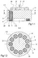
- Fig. 1 is a first embodiment of the spinning device according to the invention shown schematically.
- 1.1 is a schematic sectional view in FIG Longitudinal direction of the spinning device, in Fig. 1.2 schematically a cross section of the Spinning device and in Fig. 1.3 an enlarged section of the sectional view shown in Fig. 1.1.
- the spinning device has a heated support 17.
- the for heating the Carrier 17 required heating elements are not shown here.
- the carrier 17th serves to receive an annular spinneret 1, which is on the underside of the Carrier 17 is attached.
- the spinneret 1 has a large number of nozzle bores 5.
- An annular collecting chamber is formed above the spinneret 1, which have a lower annular outlet area 2.2 and an upper inlet area 2.1 contains.
- the outlet area 2.2 of the collecting chamber is annular formed and covers the entire surface of the spinneret 1. Within the Outlet area 2.2, a perforated plate 16 and an intermediate plate 29 are arranged.
- the perforated plate 16 contains a plurality of vertical bores 32 through which one with the annular chamber 33 formed between the spinneret 1 and the perforated plate 16 connected to the remaining sections of the outlet area 2.2 of the collection chamber is.
- the intermediate plate 29 forms the connection between the inlet area 2.1 and the outlet area 2.2 of the collection chamber.
- the inlet area 2.1 of the collection chamber is separated by several trained filter chambers 3 formed. Overall, are over the ring cross section the outlet area 2.2 eleven filter chambers 3 evenly distributed in introduced the carrier 17.
- the number of filter chambers 3 is exemplary.
- the filter chambers 3 each have an upper melt inlet 7 and a lower melt outlet 8.
- the melt outlets 8 of the filter chambers 3 are in accordance with the division of the filter chamber arrangement in the intermediate plate 29 formed.
- the inlet area 2.1 of the collecting chamber serves to receive a filter device.
- the filter device consists of several filter elements 4 which are each arranged in a filter chamber 3.
- the total of eleven filter elements 4 are hollow cylindrical and have a permeable filter jacket 11 on.
- the diameter of the filter jacket 11 is chosen such that between there is a distance between the wall of the filter chamber 3 and the filter element 4.
- the filter element 4 has an inner tube 12 which is closed at one end and is open at an opposite end.
- the open end of the inner tube 12 forms the outlet opening 10 of the filter element, which with the melt outlet 8 of the filter chamber 3 is connected.
- On the circumference of the inner tube 12 is on open end formed a circumferential collar 31 which extends in the axial direction on the intermediate plate 29 and sealing in the radial direction on the carrier 17th supported.
- the outer tube 13 encloses at a distance the inner tube 12 and extends to the closed End of the inner tube 12.
- a cover 24 is provided, which connects the inner tube 12 to the outer tube 13.
- the filter element 4 is protruding into the filter chamber 3, the collar 31 a separation in the filter chamber 3 between the melt inlet 7 and the Melt outlet 8 forms.
- the structure of the filter elements 4 of the filter device is identical, to achieve a uniform filtration of the melt.
- the melt inlets 7 of the filter chambers 3 are provided with a melt feed 6 connected.
- a distribution line system is provided, through which everyone individual filter chamber 3 is assigned a separate distribution line 15.
- the Distribution line system is fed by a spinning pump 21.
- the spinning pump 21 is connected to a melt generator, for example an extruder.
- a partial melt flow is one the melt inlets 7 supplied.
- a partial melt flow thus occurs in each of the filter chambers 3 the polymer melt.
- Distributed in the filter chamber 3 Polymer melt over the entire circumference of the filter jacket 11 and penetrates a through the openings 14 of the outer tube 13 in the filter jacket 11.
- the powdery filter material 9 is penetrated and the polymer melt is in a central through the openings 14 of the inner tube 12 Melt channel 30 initiated.
- the partial melt flow reaches the outlet area from the melt outlet 8 2.2 the collection chamber.
- the filter elements 4 have in the filter jacket 11 preferably a metal powder or quartz sand. This makes a high one Depth effect achieved in the filtration of the polymer melt.
- the Filter jacket 11 constructed and integrated in the filter chamber 3 that the Residence times of the polymer melt during the filtration are essentially independent from the point of entry are the same.
- relatively high differential pressures can be realized. The pressure load is due to the small diameter of the filter chambers in relation to the spinneret 3 limited.
- the structure of the filter element in the exemplary embodiment according to FIG. 1 is exemplary. So there is the possibility of additional filter screens inside and outside to arrange the pipes. Any filter materials can also be used insert into the jacket.
- 2 shows a further exemplary embodiment of the spinning device according to the invention shown. Components with the same function were used with identical ones Provide reference numerals. 2 is in its structure essentially identical to the previous embodiment, see above that only the essential differences are described here.
- the embodiment of the spinning device according to Fig. 2 has an annular Carrier 17.
- the annular carrier 17 is such in a heating box 20 integrated that the jacket 27 of the carrier 17 and the upper end face 28 of the carrier 17 are heated by a heat carrier contained in the heating box 20.
- the carrier 17 forms in the center a receptacle 34 for a not shown here Cooler.
- a heating element 19 is arranged on the inside 18 of the carrier 17.
- the heating element 19 is preferably designed as a heating tape that the entire inside 18 of the carrier 17 heated.
- the carrier 17 serves to receive a spinneret 1, a perforated plate 16, one Intermediate plate 29 and several filter elements 4.
- the arrangement and training the spinneret 1, the perforated plate 16, the intermediate plate 29 and the filter elements 4 is identical to the embodiment of FIG. 1, so that on the previous description is referred.
- the melt inlets 7 of the filter chambers 3 have an annular distribution channel 22 connected.
- the distribution channel 22 is via one or more melt lines 23 connected to a spinning pump 21 and a melt feed 6.
- the distribution channel 22 the melt lines 23 and the spinning pump 21 arranged in the heating box 20 and are heated.
- a polymer melt first via the spinning pump 21 in the annular Distribution channel 22 promoted.
- the polymer melt emerges from the distribution channel 22 each in partial flows in the assigned filter chambers 3. After the filtration the partial flows are brought together again in the outlet area of the collecting chamber 2.2 and mixed together. After passing through the perforated plate 16, the polymer melt becomes the plurality of filaments by means of the spinneret 1 extruded.
Landscapes
- Engineering & Computer Science (AREA)
- Mechanical Engineering (AREA)
- Textile Engineering (AREA)
- Spinning Methods And Devices For Manufacturing Artificial Fibers (AREA)
Applications Claiming Priority (2)
| Application Number | Priority Date | Filing Date | Title |
|---|---|---|---|
| DE10140581 | 2001-08-18 | ||
| DE10140581A DE10140581A1 (de) | 2001-08-18 | 2001-08-18 | Spinnvorrichtung |
Publications (1)
| Publication Number | Publication Date |
|---|---|
| EP1285981A1 true EP1285981A1 (fr) | 2003-02-26 |
Family
ID=7695888
Family Applications (1)
| Application Number | Title | Priority Date | Filing Date |
|---|---|---|---|
| EP02015685A Withdrawn EP1285981A1 (fr) | 2001-08-18 | 2002-07-18 | Dispositif de filage par extrusion de filaments |
Country Status (4)
| Country | Link |
|---|---|
| US (1) | US20030035855A1 (fr) |
| EP (1) | EP1285981A1 (fr) |
| CN (1) | CN1407144A (fr) |
| DE (1) | DE10140581A1 (fr) |
Families Citing this family (7)
| Publication number | Priority date | Publication date | Assignee | Title |
|---|---|---|---|---|
| DE10348766A1 (de) * | 2003-10-21 | 2005-06-02 | Saurer Gmbh & Co. Kg | Spinnkopf und Filtereinrichtung für derartigen Spulkopf |
| CN101845674B (zh) * | 2010-06-07 | 2011-09-28 | 扬州华美丙纶纺织有限公司 | 二层环吹风纤维喷丝头 |
| CN103320873A (zh) * | 2013-07-02 | 2013-09-25 | 昆明醋酸纤维有限公司 | 一种醋酸纤维纺丝精密剪切浆液过滤方法及装置 |
| CN108411387A (zh) * | 2018-04-20 | 2018-08-17 | 中国纺织科学研究院有限公司 | 熔体纺丝设备 |
| CN109797444B (zh) * | 2019-03-08 | 2024-04-09 | 青岛科技大学 | 一种高压电极内置便携式熔体静电纺丝装置 |
| CN110273187B (zh) * | 2019-06-18 | 2024-08-23 | 福建省长乐市天梭纺织实业有限公司 | 一种涤纶生产用纺丝工艺设备 |
| CN115418729B (zh) * | 2022-08-01 | 2023-08-08 | 浙江理工大学 | 用于制备有色超细洗涤棉复合纤维的熔体过滤装置 |
Citations (5)
| Publication number | Priority date | Publication date | Assignee | Title |
|---|---|---|---|---|
| US3071808A (en) * | 1960-06-11 | 1963-01-08 | British Nylon Spinners Ltd | Melt-spinning synthetic polymer filaments |
| US4088431A (en) * | 1974-05-07 | 1978-05-09 | Imperial Chemical Industries Limited | Melt spinning filter |
| US4494921A (en) * | 1983-08-08 | 1985-01-22 | E. I. Du Pont De Nemours And Company | Filter element |
| US4512731A (en) * | 1981-07-09 | 1985-04-23 | Celanese Corporation | Apparatus and process for filtering molten polymer |
| US4704077A (en) * | 1984-10-16 | 1987-11-03 | Barmag Ag | Melt spinning apparatus |
Family Cites Families (6)
| Publication number | Priority date | Publication date | Assignee | Title |
|---|---|---|---|---|
| DE1964051B2 (de) * | 1969-12-22 | 1976-09-23 | Zimmer Ag, 6000 Frankfurt | Verfahren zur herstellung hochmolekularer technischer filamente aus linearen plymeren |
| US4276011A (en) * | 1979-02-21 | 1981-06-30 | American Cyanamid Company | Spinnerette assembly |
| JPH06180613A (ja) * | 1992-12-14 | 1994-06-28 | Toshiba Mach Co Ltd | 加熱温度制御装置 |
| DE4338129A1 (de) * | 1993-11-08 | 1995-05-11 | Zimmer Ag | Verfahren zur Polymerschmelze-Filtration |
| US5462653A (en) * | 1994-02-15 | 1995-10-31 | Hills, Inc. | Apparatus for continuous polymer filtration |
| US6171536B1 (en) * | 1998-04-10 | 2001-01-09 | Arteva North America S.A.R.L. | Apparatus and method for melt spinning of molten polymeric material |
-
2001
- 2001-08-18 DE DE10140581A patent/DE10140581A1/de not_active Withdrawn
-
2002
- 2002-07-18 EP EP02015685A patent/EP1285981A1/fr not_active Withdrawn
- 2002-07-31 CN CN02125287.4A patent/CN1407144A/zh active Pending
- 2002-08-06 US US10/213,806 patent/US20030035855A1/en not_active Abandoned
Patent Citations (5)
| Publication number | Priority date | Publication date | Assignee | Title |
|---|---|---|---|---|
| US3071808A (en) * | 1960-06-11 | 1963-01-08 | British Nylon Spinners Ltd | Melt-spinning synthetic polymer filaments |
| US4088431A (en) * | 1974-05-07 | 1978-05-09 | Imperial Chemical Industries Limited | Melt spinning filter |
| US4512731A (en) * | 1981-07-09 | 1985-04-23 | Celanese Corporation | Apparatus and process for filtering molten polymer |
| US4494921A (en) * | 1983-08-08 | 1985-01-22 | E. I. Du Pont De Nemours And Company | Filter element |
| US4704077A (en) * | 1984-10-16 | 1987-11-03 | Barmag Ag | Melt spinning apparatus |
Also Published As
| Publication number | Publication date |
|---|---|
| US20030035855A1 (en) | 2003-02-20 |
| DE10140581A1 (de) | 2003-02-27 |
| CN1407144A (zh) | 2003-04-02 |
Similar Documents
| Publication | Publication Date | Title |
|---|---|---|
| DE3419822C2 (de) | Filtervorrichtung für Schneckenextruder | |
| EP2230336A1 (fr) | Tête de filage | |
| DE4224652C3 (de) | Spinnvorrichtung zum Schmelzspinnen insbesondere thermosplastischer Mehrkomponentenfäden | |
| EP0636190B1 (fr) | Installation de filage de fils thermoplastiques | |
| EP1285981A1 (fr) | Dispositif de filage par extrusion de filaments | |
| EP3092330A1 (fr) | Dispositif de filière | |
| DE19704621A1 (de) | Vorrichtung zum Reinigen viskosen Materials | |
| WO2012113668A1 (fr) | Dispositif de filage par fusion | |
| EP1288349B1 (fr) | Dispositif pour le filage au fondu et refroidissement de faisceaux de filaments | |
| DE1660469A1 (de) | Vorrichtung und Verfahren zum Herstellen konjugierter endloser Faeden | |
| EP1231302A1 (fr) | Dispositif pour le filage au fondu et refroidissement de faisceaux de filaments | |
| EP1678354B1 (fr) | Tete a filer et dispositif filtre pour une tete de filage | |
| EP3209820B1 (fr) | Dispositif et procédé de filage à chaud et de refroidissement d'un ensemble de filaments | |
| DE102016112170A1 (de) | Spinndüsenpaket | |
| DE102013011956A1 (de) | Spinndüsenvorrichtung | |
| DE10154859B4 (de) | Vorrichtung zum Schmelzspinnen von Mehrkomponentenfäden | |
| DE3210666A1 (de) | Fluidstrahlorgan, insbesondere fluidduese, zur herstellung texturierter bzw. strukturierter faeden | |
| EP1560952B1 (fr) | Procede et dispositif de filage par fusion et de refroidissement d'une pluralite de filaments synthetiques | |
| DE19701002A1 (de) | Vorrichtung zum Reinigen viskosen Materials | |
| CH327224A (de) | Schmelz-Spinnapparat | |
| DE4422536A1 (de) | Verfahren und Vorrichtung zur Herstellung von dünnwandigen Röhrchen | |
| DE102020007661A1 (de) | Vorrichtung zum Abkühlen einer ringförmig extrudierten Filamentschar | |
| DE10316674A1 (de) | Düsenkopf für einen Extruder | |
| DE102010005219A1 (de) | Vorrichtung zum Schmelzspinnen synthetischer Filamente | |
| DE8022113U1 (de) | Blastexturiervorrichtung |
Legal Events
| Date | Code | Title | Description |
|---|---|---|---|
| PUAI | Public reference made under article 153(3) epc to a published international application that has entered the european phase |
Free format text: ORIGINAL CODE: 0009012 |
|
| AK | Designated contracting states |
Kind code of ref document: A1 Designated state(s): AT BE BG CH CY CZ DE DK EE ES FI FR GB GR IE IT LI LU MC NL PT SE SK TR Designated state(s): AT BE BG CH CY CZ DE DK EE ES FI FR GB GR IE IT LI LU MC NL PT SE SK TR |
|
| AX | Request for extension of the european patent |
Extension state: AL LT LV MK RO SI |
|
| RIN1 | Information on inventor provided before grant (corrected) |
Inventor name: SCHIRBER, OLIVER Inventor name: DREYER, JOACHIM Inventor name: BRANDT, HOLGER Inventor name: BECK, ARNOLD Inventor name: RAVE, HENNING |
|
| 17P | Request for examination filed |
Effective date: 20030725 |
|
| AKX | Designation fees paid |
Designated state(s): CH DE IT LI |
|
| RAP1 | Party data changed (applicant data changed or rights of an application transferred) |
Owner name: SAURER GMBH & CO. KG |
|
| GRAP | Despatch of communication of intention to grant a patent |
Free format text: ORIGINAL CODE: EPIDOSNIGR1 |
|
| STAA | Information on the status of an ep patent application or granted ep patent |
Free format text: STATUS: THE APPLICATION IS DEEMED TO BE WITHDRAWN |
|
| 18D | Application deemed to be withdrawn |
Effective date: 20050114 |