EP1285983A1 - Dispositif d'entretien pour machine textile produisant des bobines croisées - Google Patents
Dispositif d'entretien pour machine textile produisant des bobines croisées Download PDFInfo
- Publication number
- EP1285983A1 EP1285983A1 EP02012291A EP02012291A EP1285983A1 EP 1285983 A1 EP1285983 A1 EP 1285983A1 EP 02012291 A EP02012291 A EP 02012291A EP 02012291 A EP02012291 A EP 02012291A EP 1285983 A1 EP1285983 A1 EP 1285983A1
- Authority
- EP
- European Patent Office
- Prior art keywords
- thread
- centering
- service unit
- guide plate
- cutting device
- Prior art date
- Legal status (The legal status is an assumption and is not a legal conclusion. Google has not performed a legal analysis and makes no representation as to the accuracy of the status listed.)
- Withdrawn
Links
- 239000004753 textile Substances 0.000 title claims description 4
- 238000005520 cutting process Methods 0.000 claims description 35
- 238000007383 open-end spinning Methods 0.000 claims description 12
- 239000002184 metal Substances 0.000 abstract 1
- 238000009987 spinning Methods 0.000 description 9
- 238000004804 winding Methods 0.000 description 5
- 235000013351 cheese Nutrition 0.000 description 4
- 238000006073 displacement reaction Methods 0.000 description 3
- 238000000034 method Methods 0.000 description 3
- 238000012546 transfer Methods 0.000 description 3
- 239000000835 fiber Substances 0.000 description 2
- 241000973497 Siphonognathus argyrophanes Species 0.000 description 1
- 238000013459 approach Methods 0.000 description 1
- 238000004140 cleaning Methods 0.000 description 1
- 230000001419 dependent effect Effects 0.000 description 1
- 238000013461 design Methods 0.000 description 1
- 238000011161 development Methods 0.000 description 1
- 230000014759 maintenance of location Effects 0.000 description 1
- 238000011017 operating method Methods 0.000 description 1
- 230000002093 peripheral effect Effects 0.000 description 1
- 238000003825 pressing Methods 0.000 description 1
Images


Classifications
-
- D—TEXTILES; PAPER
- D01—NATURAL OR MAN-MADE THREADS OR FIBRES; SPINNING
- D01H—SPINNING OR TWISTING
- D01H15/00—Piecing arrangements ; Automatic end-finding, e.g. by suction and reverse package rotation; Devices for temporarily storing yarn during piecing
- D01H15/013—Carriages travelling along the machines
-
- B—PERFORMING OPERATIONS; TRANSPORTING
- B65—CONVEYING; PACKING; STORING; HANDLING THIN OR FILAMENTARY MATERIAL
- B65H—HANDLING THIN OR FILAMENTARY MATERIAL, e.g. SHEETS, WEBS, CABLES
- B65H67/00—Replacing or removing cores, receptacles, or completed packages at paying-out, winding, or depositing stations
- B65H67/04—Arrangements for removing completed take-up packages and or replacing by cores, formers, or empty receptacles at winding or depositing stations; Transferring material between adjacent full and empty take-up elements
- B65H67/0405—Arrangements for removing completed take-up packages or for loading an empty core
- B65H67/0417—Arrangements for removing completed take-up packages or for loading an empty core for loading an empty core
- B65H67/0422—Arrangements for removing completed take-up packages or for loading an empty core for loading an empty core for loading a starter winding, i.e. a spool core with a small length of yarn wound on it; preparing the starter winding
-
- D—TEXTILES; PAPER
- D01—NATURAL OR MAN-MADE THREADS OR FIBRES; SPINNING
- D01H—SPINNING OR TWISTING
- D01H4/00—Open-end spinning machines or arrangements for imparting twist to independently moving fibres separated from slivers; Piecing arrangements therefor; Covering endless core threads with fibres by open-end spinning techniques
- D01H4/48—Piecing arrangements; Control therefor
- D01H4/50—Piecing arrangements; Control therefor for rotor spinning
-
- B—PERFORMING OPERATIONS; TRANSPORTING
- B65—CONVEYING; PACKING; STORING; HANDLING THIN OR FILAMENTARY MATERIAL
- B65H—HANDLING THIN OR FILAMENTARY MATERIAL, e.g. SHEETS, WEBS, CABLES
- B65H2701/00—Handled material; Storage means
- B65H2701/30—Handled filamentary material
- B65H2701/31—Textiles threads or artificial strands of filaments
Definitions
- the invention relates to a service unit for a Textile machine producing cross-wound bobbins according to the preamble of claim 1.
- auxiliary thread transport device has a thread delivery tube that can be pivoted into different working positions.
- a thread cutting device is integrated into the thread delivery tube at a distance from its mouth.
- the thread delivery tube can be defined either connected to a compressed air connection or to a suction air connection so that an auxiliary thread can be provided as well as disposed of by the auxiliary thread transport device.
- the thread laying device consists essentially of a pivoting thread guide and one Thread retention element, the thread guide plate a Thread guide contour with a thread guide notch and one Has thread laying slot.
- Thread guide plate that which can be acted upon by a thrust piston gear Thread guide plate is supported in its end position from the inside one of the coil frame arms.
- the Coil frame acted on something in the sense of "open” what in the worst case can lead to the fact that between the Coil frame arms in rotatable sleeve plates via friction locking held empty sleeve is insufficiently clamped so that it between sleeve and sleeve plate for a relative movement can come.
- Another disadvantage of this known device is the position of the thread cutting device. This means that the arrangement of the thread cutting device within the thread delivery tube provides a relatively large distance from the delivery tube mouth and thus also to the thread catching devices of the tube plate, with the result that after winding the thread start reserve, a relatively long thread end remains, which is very difficult to close is secure and often leads to the fact that the thread start reserve is destroyed again during the winding process.
- This known service unit has a swivel arm on which a thread delivery tube and a so-called manipulator with a head element which can be displaced in the direction of the bobbin frame are arranged.
- the manipulator acts during the thread transfer with a device arranged at the head end of a baffle arranged on the bobbin frame in the sense of "closing the frame” and thereby reliably prevents that there can be a harmful relative movement between the thread catcher arranged on the tube plate and the empty tube during the thread transfer.
- the empty sleeve is fixed between the sleeve plates with such a pressing force that it is ensured that the thread catching device arranged on the sleeve plate rotates in synchronism with the empty sleeve.
- a device arranged on the head element in the form of a thread guide edge also ensures that the thread produced in the open-end spinning device is first transferred to a thread catching device arranged on the tube plate and the collected thread is then deposited in a defined manner on the empty tube.
- Thread cutting device is closer to the mouth of the Thread delivery tube has been brought up, the Thread cutting device is still in that Delivery tube integrated, so that the above problems with unsecured thread ends not described could be completely eliminated.
- the The invention is therefore based on the object of a service unit to improve in that a correct application of the thread produced in the open-end spinning device empty tube held in the coil frame, in particular a secure one Setting the thread end is guaranteed.
- the embodiment of the invention has the particular advantage that the thread that is to be placed on an empty tube that is held between the tube plates of a bobbin frame is separated immediately next to the thread catching devices of the tube plate. This creates a relatively short thread end, which is also largely overwound by the thread start reserve and is thus securely fixed on the sleeve.
- the centering and guide plate which carries the thread cutting device according to the invention, by means of a thrust piston gear in an operating position right next to the pod, which the Has thread catcher, can be retracted. In this operating position, the centering and Guide plate with a centering gap on a centering approach Bobbin frame, so that the thread cutting device is always exact is positioned.
- Thread cutting device in an advantageous embodiment hook-shaped base body partially open towards the inside.
- a fixed cutting edge is integrated in the base body, one, viewed in side view, inclined at 45 ° Has cutting edge.
- Such a design ensures, on the one hand, that the thread produced in the open-end spinning device, initially still sucked off via the thread delivery tube, as soon as it has been gripped by the thread catching device of the core plate, is pulled over the cutting edge and thereby separated.
- such an arrangement of the cutting edge ensures that the operating personnel cannot accidentally come into contact with the cutting edge and injure themselves in the process.
- Open-end spinning machines of this type generally have a multiplicity of work stations 2 of the same type, each of which is equipped with a spinning device 3 and a winding device 4.
- the spinning device 3 the sliver 6 placed in a spinning can 5 is spun into a thread 7, which is then wound up on the winding device 4 to form a cheese 8.
- the spooling devices 4 have a spool frame 9 for rotatably holding a sleeve 10 and a spool drum 11 for driving the sleeve 10 or the cheese 8.
- the mostly double-row open-end spinning machines 1 have between their rows of jobs often a coil transport device 12, via the Completed packages 8 are disposed of.
- a service unit 16 a so-called piecing carriage, is arranged on or on the spinning machine 1, movable on guide rails 13, 14 and support rails 15.
- the drive 17 of the service unit 16 has rollers 18 or support wheels 19.
- the service unit 16 is supplied with electrical energy via a drag chain or, as indicated in FIG. 1, via a sliding contact device 20.
- Such service units 16 patrol along the work stations 2 of the open-end spinning machine 1 and intervene automatically when there is a need for action at one of the work stations 2.
- Such a need for action exists, for example, when one of the workplaces 2 has broken a thread or if a cheese 8 at one of the workstations has reached the prescribed diameter and against a Empty sleeve 10 must be replaced.
- the service unit 16 runs to the concerned job 2, positions itself there and searches in the case of a "normal" thread break with its thread search nozzle 21 the cracked, on the peripheral surface of the package 8 Accumulated thread end.
- FIG. 2 schematically shows a service unit 16 with its most important thread handling elements necessary for carrying out the aforementioned operating cases.
- Service unit 16 includes, among other things, a pivotally mounted thread search nozzle 21, the suction slot of which can be placed on the outer circumference of the package 8 can accommodate torn thread ends.
- the service unit 16 is also, as is known, equipped with a thread catcher 25, a thread puller 26, a thread feeder 27 with feed tongs 28 and thread separating device 29 and with a controllable thread take-off device consisting of a drivable take-off roller 30 and a pivotably arranged pressure roller 31.
- a frame opener 32, a pressure lever 33 and an auxiliary thread delivery and disposal device 34 are installed in the service unit 16 as further operating elements.
- the auxiliary thread delivery and disposal device 34 has in this case, for example, via a pipe system 35 which has a flexible connecting element 36, for example a hose, with one that can be swiveled into different positions Delivery tube 37 is connected.
- the delivery tube 37 is in turn fixed to a swivel arm 38 which is about a swivel axis 39 is pivotally defined.
- the pipe system 35 into which an auxiliary thread 45 drawn off from a supply spool 44 can be fed via a thread feed mechanism 43, has one in the entrance area Suction air connection 40, which can be activated via a valve 41, and a compressed air connection 46, which can be activated via a valve 47. Furthermore, a first thread separating device 42 can be arranged in the upper region of the pipe system 35.
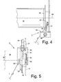
- the thread cutting device 51 according to the invention is shown in FIGS Figures 3 to 5 shown in more detail.
- FIG. 3 shows a side view of the front part of a bobbin frame arm of the bobbin frame 9, the thread delivery tube 37 and the centering and guide plate 50 carrying the thread cutting device 51.
- the end of the bobbin frame arm has a centering shoulder 55. It is also on the coil frame arm to a Rotation axis 60 freely rotatable, a sleeve plate 52 rotatably mounted, which is equipped on its outer circumference with a thread catching device 53.
- the centering and guide plate 50 is fixed on the piston rod 49 of a thrust piston gear 48, and can be moved into the operating position I shown by means of this thrust piston gear 48.
- the centering and guide plate 50 carries on its back the thread cutting device 51 according to the invention, which essentially consists of a base body 56 and a cutting edge 57.
- the base body 56 is hook-shaped, that is to say the base body 56 is partially open at the bottom.
- the cutting edge 57 is fixed within the base body opening, the cutting edge 58 of which, as shown, extends at an angle of approximately 45 °.
- FIG. 5 shows that the centering and guide plate 50 has a thread guide gap 59 in addition to a centering gap 54.
- the thread 7 guided in the thread guide gap 59 is guided to create a thread start reserve by lateral displacement of the centering and guide plate 50 such that the thread end cut by the thread cutting device 51 is wound over and is thereby fixed to the sleeve 10.
- the service unit 16 runs to the relevant work station 2, positions itself there and changes the full package 8 against an empty tube 10. The service unit 16 then spins the spinning device 3 of the relevant work station 2 again.
- the swivel arm 38 carrying the delivery tube 37 of the auxiliary thread delivery device 34 is in a rear position (not shown) for transferring an auxiliary thread 45 to the suction nozzle 21.
- the mouth of the delivery tube 37 is so in the region of the suction slot of the suction nozzle 21 that an auxiliary thread 45 delivered via the auxiliary thread delivery device 34 and emerging from the mouth of the delivery tube 37 can be immediately grasped by the suction nozzle 21.
- the pivot arm 38 is then pivoted into its front position, which is indicated in FIG. 2. This creates a thread chord (not shown) which, as is known and therefore not explained in more detail, is gripped by the thread handling elements of the service unit 16 described above.
- the thread is then, as usual, prepared and spun in the open-end spinning device 3 to a fiber ring running there.
- the thread 7 produced in the open-end spinning device 3 is first sucked off via the thread feed tube 37 following the auxiliary thread 45.
- the mouth of the thread delivery tube 37 is at this point in the area of the bobbin frame 9. That is, the mouth of the thread delivery tube 37 is positioned somewhat offset above the axis of rotation 60 of the bobbin frame arm.
- a thrust piston gear 48 arranged on the swivel arm 38 or the centering and guide plate 51 arranged on the piston rod 49 of the thrust piston gear 48 the thread 7 is brought into the area of a thread catching device 53 arranged on the sleeve plate 52 of the bobbin frame 9 and is grasped by the latter.
- the thread catching device 53 rotating in the direction R then ensures that the thread 7 held in the thread catching device 53 slides over the cutting edge 58 of the thread cutting device 51 and is thereby cut.
- a (not shown) push piston mechanism which is arranged parallel to the axis of rotation 60, provides for a lateral displacement of the previously slightly raised centering and guide plate 50 and thereby for the creation of a (not illustrated) thread start reserve. That is, the thread 7 guided in the thread guide gap 59 of the centering and guide plate 50 is wound with lateral displacement on the empty tube 10 so that the thread reserve thus created winds over the thread end and thereby secures it on the tube 10.
Landscapes
- Engineering & Computer Science (AREA)
- Textile Engineering (AREA)
- Mechanical Engineering (AREA)
- Replacing, Conveying, And Pick-Finding For Filamentary Materials (AREA)
- Spinning Or Twisting Of Yarns (AREA)
Applications Claiming Priority (2)
| Application Number | Priority Date | Filing Date | Title |
|---|---|---|---|
| DE10141046 | 2001-08-22 | ||
| DE10141046A DE10141046A1 (de) | 2001-08-22 | 2001-08-22 | Serviceaggregat für eine Kreuzspulen herstellende Textilmaschine |
Publications (1)
| Publication Number | Publication Date |
|---|---|
| EP1285983A1 true EP1285983A1 (fr) | 2003-02-26 |
Family
ID=7696189
Family Applications (1)
| Application Number | Title | Priority Date | Filing Date |
|---|---|---|---|
| EP02012291A Withdrawn EP1285983A1 (fr) | 2001-08-22 | 2002-06-05 | Dispositif d'entretien pour machine textile produisant des bobines croisées |
Country Status (5)
| Country | Link |
|---|---|
| US (1) | US20030038205A1 (fr) |
| EP (1) | EP1285983A1 (fr) |
| CN (1) | CN1407155A (fr) |
| CZ (1) | CZ20022315A3 (fr) |
| DE (1) | DE10141046A1 (fr) |
Cited By (2)
| Publication number | Priority date | Publication date | Assignee | Title |
|---|---|---|---|---|
| CN108642616A (zh) * | 2018-05-22 | 2018-10-12 | 卓郎(江苏)纺织机械有限公司 | 具有纺纱器打开状态检测装置的转杯纺纱机 |
| EP3431427A1 (fr) * | 2017-07-19 | 2019-01-23 | Maschinenfabrik Rieter AG | Procédé de fonctionnement d'un poste de travail d'un métier à filer ou d'un bobinoire et buse de fil |
Families Citing this family (5)
| Publication number | Priority date | Publication date | Assignee | Title |
|---|---|---|---|---|
| DE102007056561A1 (de) * | 2007-08-25 | 2009-02-26 | Oerlikon Textile Gmbh & Co. Kg | Kreuzspulen herstellende Textilmaschine |
| DE102007048720B4 (de) * | 2007-10-11 | 2019-01-31 | Saurer Spinning Solutions Gmbh & Co. Kg | Verfahren und Vorrichtung zum Betreiben einer Offenend-Rotorspinnmaschine |
| DE102019129499A1 (de) * | 2019-10-31 | 2021-05-06 | Saurer Spinning Solutions Gmbh & Co. Kg | Offenend-Spinnmaschine sowie Verfahren und Steuereinrichtung zum Betreiben einer solchen Offenend-Spinnmaschine |
| DE102021102752A1 (de) * | 2020-02-15 | 2021-08-19 | Oerlikon Textile Gmbh & Co. Kg | Verfahren zum Abnehmen von Fadenspulen und Spulenabnehmer |
| CN118308813B (zh) * | 2024-05-06 | 2026-01-16 | 浙江宝耀智能科技有限公司 | 一种移动式气流纺更换纱筒装置 |
Citations (4)
| Publication number | Priority date | Publication date | Assignee | Title |
|---|---|---|---|---|
| US3816990A (en) * | 1972-03-23 | 1974-06-18 | Krupp Gmbh | Device for exchanging bobbins on an open-end spinning machine |
| US4817380A (en) * | 1985-06-24 | 1989-04-04 | Schubert & Salzer | Process and device for piecing up an open-end friction spinning device |
| EP0473212A1 (fr) * | 1990-08-01 | 1992-03-04 | SAVIO MACCHINE TESSILI S.r.l. | Dispositif et procédé pour attraper et préparer le bout du fil pour le rattacher dans un métier à filer à bout libre |
| DE19917969A1 (de) * | 1999-04-21 | 2000-10-26 | Schlafhorst & Co W | Serviceaggregat für eine Kreuzspulen herstellende Textilmaschine |
Family Cites Families (15)
| Publication number | Priority date | Publication date | Assignee | Title |
|---|---|---|---|---|
| DE2501735A1 (de) * | 1975-01-17 | 1976-07-22 | Schlafhorst & Co W | Verfahren und vorrichtung zur automatisierung des auflaufspulenwechsels an einer spinnmaschine, insbesondere rotor- spinnmaschine |
| GB1536939A (en) * | 1975-04-17 | 1978-12-29 | Teijin Ltd | Method and device for forming a bunch winding on a fresh bobbin at the time of a doffing and donning operation |
| DE2542000C3 (de) * | 1975-09-20 | 1978-03-09 | Fried. Krupp Gmbh, 4300 Essen | Verfahren und Vorrichtung zum Bilden eines Anknüpftadens bestimmter Länge an Spulen von Textilmaschinen |
| DE3123494C2 (de) * | 1981-06-13 | 1992-07-09 | Schubert & Salzer Maschinenfabrik Ag, 8070 Ingolstadt | Verfahren und Vorrichtung zum Aufwinden eines neu angesponnenen Fadens auf eine in eine Spulvorrichtung eingelegte Leerhülse |
| JPS6077072A (ja) * | 1983-10-03 | 1985-05-01 | Yoshida Kogyo Kk <Ykk> | ワインダ−に対する糸掛け方法およびその装置 |
| IT1202589B (it) * | 1987-02-27 | 1989-02-09 | Savio Spa | Dispositivo e procedimento per la levata autromatica delle rocche in una macchina roccatrice |
| DE3734478A1 (de) * | 1987-10-12 | 1989-04-27 | Schubert & Salzer Maschinen | Verfahren und vorrichtung zum fuehren, halten und trennen eines fadens beim spulenwechsel |
| DE9100376U1 (de) * | 1990-01-20 | 1991-04-04 | Hacoba Textilmaschinen Gmbh & Co Kg, 5600 Wuppertal | Spulmaschine |
| DE4432702B4 (de) * | 1994-09-14 | 2005-08-18 | Saurer Gmbh & Co. Kg | Serviceeinrichtung für eine Kreuzspulen herstellende Textilmaschine |
| DE19517690A1 (de) * | 1995-05-13 | 1996-11-14 | Fritz Stahlecker | Vorrichtung zum Bilden einer Fadenreservewicklung nach einem Spulenwechsel an einem Spinnaggregat |
| DE19533833B4 (de) * | 1995-09-13 | 2004-08-05 | Saurer Gmbh & Co. Kg | Kreuzspulenwechseleinrichtung einer Kreuzspulen herstellenden Textilmaschine |
| DE19931878A1 (de) * | 1999-07-09 | 2001-01-18 | Rieter Ingolstadt Spinnerei | Verfahren und Vorrichtung zum Warten einer Textilmaschine |
| DE10007954B4 (de) * | 2000-02-22 | 2009-02-05 | Oerlikon Textile Gmbh & Co. Kg | Spulvorrichtung für eine Kreuzspulen herstellende Textilmaschine |
| US6375114B1 (en) * | 2000-06-29 | 2002-04-23 | Rieter Ingolstadt Spinnereimaschinenbau Ag | Process and an apparatus for the servicing of a textile machine |
| DE10139072B4 (de) * | 2001-08-09 | 2009-12-17 | Oerlikon Textile Gmbh & Co. Kg | Serviceaggregat zum Wiederanspinnen von Arbeitsstellen einer Offenend-Spinnmaschine |
-
2001
- 2001-08-22 DE DE10141046A patent/DE10141046A1/de not_active Withdrawn
-
2002
- 2002-06-05 EP EP02012291A patent/EP1285983A1/fr not_active Withdrawn
- 2002-07-02 CZ CZ20022315A patent/CZ20022315A3/cs unknown
- 2002-08-20 US US10/224,662 patent/US20030038205A1/en not_active Abandoned
- 2002-08-22 CN CN02130124.7A patent/CN1407155A/zh active Pending
Patent Citations (4)
| Publication number | Priority date | Publication date | Assignee | Title |
|---|---|---|---|---|
| US3816990A (en) * | 1972-03-23 | 1974-06-18 | Krupp Gmbh | Device for exchanging bobbins on an open-end spinning machine |
| US4817380A (en) * | 1985-06-24 | 1989-04-04 | Schubert & Salzer | Process and device for piecing up an open-end friction spinning device |
| EP0473212A1 (fr) * | 1990-08-01 | 1992-03-04 | SAVIO MACCHINE TESSILI S.r.l. | Dispositif et procédé pour attraper et préparer le bout du fil pour le rattacher dans un métier à filer à bout libre |
| DE19917969A1 (de) * | 1999-04-21 | 2000-10-26 | Schlafhorst & Co W | Serviceaggregat für eine Kreuzspulen herstellende Textilmaschine |
Cited By (4)
| Publication number | Priority date | Publication date | Assignee | Title |
|---|---|---|---|---|
| EP3431427A1 (fr) * | 2017-07-19 | 2019-01-23 | Maschinenfabrik Rieter AG | Procédé de fonctionnement d'un poste de travail d'un métier à filer ou d'un bobinoire et buse de fil |
| US10829338B2 (en) | 2017-07-19 | 2020-11-10 | Maschinenfabrik Rieter Ag | Method for operating a workstation of a spinning machine or winding machine |
| CN108642616A (zh) * | 2018-05-22 | 2018-10-12 | 卓郎(江苏)纺织机械有限公司 | 具有纺纱器打开状态检测装置的转杯纺纱机 |
| CN108642616B (zh) * | 2018-05-22 | 2021-03-26 | 卓郎(江苏)纺织机械有限公司 | 具有纺纱器打开状态检测装置的转杯纺纱机 |
Also Published As
| Publication number | Publication date |
|---|---|
| CZ20022315A3 (cs) | 2003-04-16 |
| DE10141046A1 (de) | 2003-03-06 |
| CN1407155A (zh) | 2003-04-02 |
| US20030038205A1 (en) | 2003-02-27 |
Similar Documents
| Publication | Publication Date | Title |
|---|---|---|
| EP1284313B1 (fr) | Procédé et dispositif de réamorçage de filature après changement de bobine sur une machine open-end | |
| DE10139074B4 (de) | Offenend-Rotorspinnmaschine | |
| EP2657380B1 (fr) | Procédé et dispositif de fonctionnement de postes de travail d'un métier à tisser à rotor à extrémité ouverte | |
| DE10139072B4 (de) | Serviceaggregat zum Wiederanspinnen von Arbeitsstellen einer Offenend-Spinnmaschine | |
| DE2939675A1 (de) | Spulenwechseleinrichtung fuer textilmaschinen | |
| CH618741A5 (fr) | ||
| DE10139075A1 (de) | Offenend-Rotorspinnmaschine | |
| DE102007048720B4 (de) | Verfahren und Vorrichtung zum Betreiben einer Offenend-Rotorspinnmaschine | |
| EP0716169B1 (fr) | Machine textile pour la fabrication de bobines à spires croisées | |
| DE4313523C2 (de) | Kreuzspulen herstellende OE-Spinnmaschine | |
| EP2444348B1 (fr) | Poignée de tube pour un agrégat de changement de bobines croisées | |
| DE102006047288A1 (de) | Arbeitsstelle einer Textilmaschine | |
| EP0805118A1 (fr) | Tête de bobinage pour la production des bobines croisées pour machines textiles | |
| EP1127831B1 (fr) | Dispositif de mise en service d'un poste de travail d'une machine textile pour la fabrication de bobines à spires croisées | |
| DE10201533B4 (de) | Offenend-Rotorspinnmaschine | |
| EP1285983A1 (fr) | Dispositif d'entretien pour machine textile produisant des bobines croisées | |
| DE19827605A1 (de) | Verfahren und Vorrichtung zum Aufnehmen eines Fadenendes von der Oberfläche einer Kreuzspule | |
| EP2824054B1 (fr) | Poste de travail d'une machine textile fabriquant des bobines croisées | |
| DE19858986A1 (de) | Bedienaggregat für eine Faserband verarbeitende Textilmaschine | |
| DE19917969A1 (de) | Serviceaggregat für eine Kreuzspulen herstellende Textilmaschine | |
| EP4051832B1 (fr) | Métier à filer à bout libre, procédé de controle de ce métier à filer et unité de controle | |
| EP0156306B1 (fr) | Bobinoir | |
| DE19935695A1 (de) | Verfahren zum Umrüsten und gleichzeitigen Modernisieren einer Offenend-Rotorspinnmaschine | |
| DE10117311C1 (de) | Verfahren und Vorrichtung zum Führen bifilar zulaufender synthetischer Fäden | |
| DE19939801A1 (de) | Serviceaggregat für eine Kreuzspulen herstellende Textilmaschine |
Legal Events
| Date | Code | Title | Description |
|---|---|---|---|
| PUAI | Public reference made under article 153(3) epc to a published international application that has entered the european phase |
Free format text: ORIGINAL CODE: 0009012 |
|
| AK | Designated contracting states |
Kind code of ref document: A1 Designated state(s): AT BE CH CY DE DK ES FI FR GB GR IE IT LI LU MC NL PT SE TR Designated state(s): AT BE CH CY DE DK ES FI FR GB GR IE IT LI LU MC NL PT SE TR |
|
| AX | Request for extension of the european patent |
Extension state: AL LT LV MK RO SI |
|
| RAP1 | Party data changed (applicant data changed or rights of an application transferred) |
Owner name: SAURER GMBH & CO. KG |
|
| 17P | Request for examination filed |
Effective date: 20030826 |
|
| AKX | Designation fees paid |
Designated state(s): CH DE IT LI |
|
| STAA | Information on the status of an ep patent application or granted ep patent |
Free format text: STATUS: THE APPLICATION IS DEEMED TO BE WITHDRAWN |
|
| 18D | Application deemed to be withdrawn |
Effective date: 20050104 |