EP1286033B1 - Verfahren zum Betreiben einer Brennkraftmaschine sowie Anfahrregler für ein Kraftfahrzeug - Google Patents
Verfahren zum Betreiben einer Brennkraftmaschine sowie Anfahrregler für ein Kraftfahrzeug Download PDFInfo
- Publication number
- EP1286033B1 EP1286033B1 EP02017006.4A EP02017006A EP1286033B1 EP 1286033 B1 EP1286033 B1 EP 1286033B1 EP 02017006 A EP02017006 A EP 02017006A EP 1286033 B1 EP1286033 B1 EP 1286033B1
- Authority
- EP
- European Patent Office
- Prior art keywords
- rotational speed
- speed
- torque
- model
- value
- Prior art date
- Legal status (The legal status is an assumption and is not a legal conclusion. Google has not performed a legal analysis and makes no representation as to the accuracy of the status listed.)
- Expired - Lifetime
Links
- 238000000034 method Methods 0.000 title claims description 32
- 238000002485 combustion reaction Methods 0.000 title claims description 18
- 230000008859 change Effects 0.000 claims description 37
- 230000006870 function Effects 0.000 claims description 12
- 230000008569 process Effects 0.000 claims description 6
- 230000004913 activation Effects 0.000 claims description 3
- 230000009849 deactivation Effects 0.000 claims description 3
- 230000015572 biosynthetic process Effects 0.000 claims 1
- 238000011144 upstream manufacturing Methods 0.000 claims 1
- 230000008901 benefit Effects 0.000 description 4
- 238000010586 diagram Methods 0.000 description 4
- 230000007704 transition Effects 0.000 description 3
- 230000006978 adaptation Effects 0.000 description 2
- 230000006399 behavior Effects 0.000 description 2
- 238000006243 chemical reaction Methods 0.000 description 2
- 230000001419 dependent effect Effects 0.000 description 2
- 230000004044 response Effects 0.000 description 2
- 230000003213 activating effect Effects 0.000 description 1
- 230000033228 biological regulation Effects 0.000 description 1
- 230000002349 favourable effect Effects 0.000 description 1
- 238000000926 separation method Methods 0.000 description 1
- 230000001629 suppression Effects 0.000 description 1
- 230000001960 triggered effect Effects 0.000 description 1
Images


Classifications
-
- B—PERFORMING OPERATIONS; TRANSPORTING
- B60—VEHICLES IN GENERAL
- B60W—CONJOINT CONTROL OF VEHICLE SUB-UNITS OF DIFFERENT TYPE OR DIFFERENT FUNCTION; CONTROL SYSTEMS SPECIALLY ADAPTED FOR HYBRID VEHICLES; ROAD VEHICLE DRIVE CONTROL SYSTEMS FOR PURPOSES NOT RELATED TO THE CONTROL OF A PARTICULAR SUB-UNIT
- B60W30/00—Purposes of road vehicle drive control systems not related to the control of a particular sub-unit, e.g. of systems using conjoint control of vehicle sub-units
- B60W30/18—Propelling the vehicle
-
- B—PERFORMING OPERATIONS; TRANSPORTING
- B60—VEHICLES IN GENERAL
- B60W—CONJOINT CONTROL OF VEHICLE SUB-UNITS OF DIFFERENT TYPE OR DIFFERENT FUNCTION; CONTROL SYSTEMS SPECIALLY ADAPTED FOR HYBRID VEHICLES; ROAD VEHICLE DRIVE CONTROL SYSTEMS FOR PURPOSES NOT RELATED TO THE CONTROL OF A PARTICULAR SUB-UNIT
- B60W10/00—Conjoint control of vehicle sub-units of different type or different function
- B60W10/02—Conjoint control of vehicle sub-units of different type or different function including control of driveline clutches
-
- B—PERFORMING OPERATIONS; TRANSPORTING
- B60—VEHICLES IN GENERAL
- B60W—CONJOINT CONTROL OF VEHICLE SUB-UNITS OF DIFFERENT TYPE OR DIFFERENT FUNCTION; CONTROL SYSTEMS SPECIALLY ADAPTED FOR HYBRID VEHICLES; ROAD VEHICLE DRIVE CONTROL SYSTEMS FOR PURPOSES NOT RELATED TO THE CONTROL OF A PARTICULAR SUB-UNIT
- B60W10/00—Conjoint control of vehicle sub-units of different type or different function
- B60W10/04—Conjoint control of vehicle sub-units of different type or different function including control of propulsion units
-
- B—PERFORMING OPERATIONS; TRANSPORTING
- B60—VEHICLES IN GENERAL
- B60W—CONJOINT CONTROL OF VEHICLE SUB-UNITS OF DIFFERENT TYPE OR DIFFERENT FUNCTION; CONTROL SYSTEMS SPECIALLY ADAPTED FOR HYBRID VEHICLES; ROAD VEHICLE DRIVE CONTROL SYSTEMS FOR PURPOSES NOT RELATED TO THE CONTROL OF A PARTICULAR SUB-UNIT
- B60W30/00—Purposes of road vehicle drive control systems not related to the control of a particular sub-unit, e.g. of systems using conjoint control of vehicle sub-units
- B60W30/18—Propelling the vehicle
- B60W30/18009—Propelling the vehicle related to particular drive situations
- B60W30/18027—Drive off, accelerating from standstill
-
- B—PERFORMING OPERATIONS; TRANSPORTING
- B60—VEHICLES IN GENERAL
- B60W—CONJOINT CONTROL OF VEHICLE SUB-UNITS OF DIFFERENT TYPE OR DIFFERENT FUNCTION; CONTROL SYSTEMS SPECIALLY ADAPTED FOR HYBRID VEHICLES; ROAD VEHICLE DRIVE CONTROL SYSTEMS FOR PURPOSES NOT RELATED TO THE CONTROL OF A PARTICULAR SUB-UNIT
- B60W30/00—Purposes of road vehicle drive control systems not related to the control of a particular sub-unit, e.g. of systems using conjoint control of vehicle sub-units
- B60W30/18—Propelling the vehicle
- B60W30/1819—Propulsion control with control means using analogue circuits, relays or mechanical links
-
- F—MECHANICAL ENGINEERING; LIGHTING; HEATING; WEAPONS; BLASTING
- F02—COMBUSTION ENGINES; HOT-GAS OR COMBUSTION-PRODUCT ENGINE PLANTS
- F02D—CONTROLLING COMBUSTION ENGINES
- F02D31/00—Use of speed-sensing governors to control combustion engines, not otherwise provided for
- F02D31/001—Electric control of rotation speed
- F02D31/007—Electric control of rotation speed controlling fuel supply
-
- F—MECHANICAL ENGINEERING; LIGHTING; HEATING; WEAPONS; BLASTING
- F02—COMBUSTION ENGINES; HOT-GAS OR COMBUSTION-PRODUCT ENGINE PLANTS
- F02D—CONTROLLING COMBUSTION ENGINES
- F02D37/00—Non-electrical conjoint control of two or more functions of engines, not otherwise provided for
- F02D37/02—Non-electrical conjoint control of two or more functions of engines, not otherwise provided for one of the functions being ignition
-
- F—MECHANICAL ENGINEERING; LIGHTING; HEATING; WEAPONS; BLASTING
- F02—COMBUSTION ENGINES; HOT-GAS OR COMBUSTION-PRODUCT ENGINE PLANTS
- F02D—CONTROLLING COMBUSTION ENGINES
- F02D41/00—Electrical control of supply of combustible mixture or its constituents
- F02D41/02—Circuit arrangements for generating control signals
- F02D41/021—Introducing corrections for particular conditions exterior to the engine
-
- F—MECHANICAL ENGINEERING; LIGHTING; HEATING; WEAPONS; BLASTING
- F02—COMBUSTION ENGINES; HOT-GAS OR COMBUSTION-PRODUCT ENGINE PLANTS
- F02D—CONTROLLING COMBUSTION ENGINES
- F02D41/00—Electrical control of supply of combustible mixture or its constituents
- F02D41/02—Circuit arrangements for generating control signals
- F02D41/04—Introducing corrections for particular operating conditions
- F02D41/10—Introducing corrections for particular operating conditions for acceleration
-
- F—MECHANICAL ENGINEERING; LIGHTING; HEATING; WEAPONS; BLASTING
- F02—COMBUSTION ENGINES; HOT-GAS OR COMBUSTION-PRODUCT ENGINE PLANTS
- F02P—IGNITION, OTHER THAN COMPRESSION IGNITION, FOR INTERNAL-COMBUSTION ENGINES; TESTING OF IGNITION TIMING IN COMPRESSION-IGNITION ENGINES
- F02P5/00—Advancing or retarding ignition; Control therefor
- F02P5/04—Advancing or retarding ignition; Control therefor automatically, as a function of the working conditions of the engine or vehicle or of the atmospheric conditions
- F02P5/145—Advancing or retarding ignition; Control therefor automatically, as a function of the working conditions of the engine or vehicle or of the atmospheric conditions using electrical means
- F02P5/15—Digital data processing
- F02P5/1502—Digital data processing using one central computing unit
- F02P5/1504—Digital data processing using one central computing unit with particular means during a transient phase, e.g. acceleration, deceleration, gear change
-
- B—PERFORMING OPERATIONS; TRANSPORTING
- B60—VEHICLES IN GENERAL
- B60W—CONJOINT CONTROL OF VEHICLE SUB-UNITS OF DIFFERENT TYPE OR DIFFERENT FUNCTION; CONTROL SYSTEMS SPECIALLY ADAPTED FOR HYBRID VEHICLES; ROAD VEHICLE DRIVE CONTROL SYSTEMS FOR PURPOSES NOT RELATED TO THE CONTROL OF A PARTICULAR SUB-UNIT
- B60W50/00—Details of control systems for road vehicle drive control not related to the control of a particular sub-unit, e.g. process diagnostic or vehicle driver interfaces
- B60W2050/0001—Details of the control system
- B60W2050/0002—Automatic control, details of type of controller or control system architecture
- B60W2050/0008—Feedback, closed loop systems or details of feedback error signal
- B60W2050/001—Proportional integral [PI] controller
-
- B—PERFORMING OPERATIONS; TRANSPORTING
- B60—VEHICLES IN GENERAL
- B60W—CONJOINT CONTROL OF VEHICLE SUB-UNITS OF DIFFERENT TYPE OR DIFFERENT FUNCTION; CONTROL SYSTEMS SPECIALLY ADAPTED FOR HYBRID VEHICLES; ROAD VEHICLE DRIVE CONTROL SYSTEMS FOR PURPOSES NOT RELATED TO THE CONTROL OF A PARTICULAR SUB-UNIT
- B60W50/00—Details of control systems for road vehicle drive control not related to the control of a particular sub-unit, e.g. process diagnostic or vehicle driver interfaces
- B60W2050/0001—Details of the control system
- B60W2050/0043—Signal treatments, identification of variables or parameters, parameter estimation or state estimation
- B60W2050/0052—Filtering, filters
-
- B—PERFORMING OPERATIONS; TRANSPORTING
- B60—VEHICLES IN GENERAL
- B60W—CONJOINT CONTROL OF VEHICLE SUB-UNITS OF DIFFERENT TYPE OR DIFFERENT FUNCTION; CONTROL SYSTEMS SPECIALLY ADAPTED FOR HYBRID VEHICLES; ROAD VEHICLE DRIVE CONTROL SYSTEMS FOR PURPOSES NOT RELATED TO THE CONTROL OF A PARTICULAR SUB-UNIT
- B60W2540/00—Input parameters relating to occupants
- B60W2540/10—Accelerator pedal position
-
- B—PERFORMING OPERATIONS; TRANSPORTING
- B60—VEHICLES IN GENERAL
- B60W—CONJOINT CONTROL OF VEHICLE SUB-UNITS OF DIFFERENT TYPE OR DIFFERENT FUNCTION; CONTROL SYSTEMS SPECIALLY ADAPTED FOR HYBRID VEHICLES; ROAD VEHICLE DRIVE CONTROL SYSTEMS FOR PURPOSES NOT RELATED TO THE CONTROL OF A PARTICULAR SUB-UNIT
- B60W2540/00—Input parameters relating to occupants
- B60W2540/14—Clutch pedal position
-
- B—PERFORMING OPERATIONS; TRANSPORTING
- B60—VEHICLES IN GENERAL
- B60W—CONJOINT CONTROL OF VEHICLE SUB-UNITS OF DIFFERENT TYPE OR DIFFERENT FUNCTION; CONTROL SYSTEMS SPECIALLY ADAPTED FOR HYBRID VEHICLES; ROAD VEHICLE DRIVE CONTROL SYSTEMS FOR PURPOSES NOT RELATED TO THE CONTROL OF A PARTICULAR SUB-UNIT
- B60W2710/00—Output or target parameters relating to a particular sub-units
- B60W2710/06—Combustion engines, Gas turbines
- B60W2710/0644—Engine speed
-
- F—MECHANICAL ENGINEERING; LIGHTING; HEATING; WEAPONS; BLASTING
- F02—COMBUSTION ENGINES; HOT-GAS OR COMBUSTION-PRODUCT ENGINE PLANTS
- F02D—CONTROLLING COMBUSTION ENGINES
- F02D41/00—Electrical control of supply of combustible mixture or its constituents
- F02D41/02—Circuit arrangements for generating control signals
- F02D41/14—Introducing closed-loop corrections
- F02D41/1401—Introducing closed-loop corrections characterised by the control or regulation method
- F02D2041/1409—Introducing closed-loop corrections characterised by the control or regulation method using at least a proportional, integral or derivative controller
-
- F—MECHANICAL ENGINEERING; LIGHTING; HEATING; WEAPONS; BLASTING
- F02—COMBUSTION ENGINES; HOT-GAS OR COMBUSTION-PRODUCT ENGINE PLANTS
- F02D—CONTROLLING COMBUSTION ENGINES
- F02D41/00—Electrical control of supply of combustible mixture or its constituents
- F02D41/02—Circuit arrangements for generating control signals
- F02D41/14—Introducing closed-loop corrections
- F02D41/1401—Introducing closed-loop corrections characterised by the control or regulation method
- F02D2041/1433—Introducing closed-loop corrections characterised by the control or regulation method using a model or simulation of the system
-
- F—MECHANICAL ENGINEERING; LIGHTING; HEATING; WEAPONS; BLASTING
- F02—COMBUSTION ENGINES; HOT-GAS OR COMBUSTION-PRODUCT ENGINE PLANTS
- F02D—CONTROLLING COMBUSTION ENGINES
- F02D2250/00—Engine control related to specific problems or objectives
- F02D2250/18—Control of the engine output torque
-
- Y—GENERAL TAGGING OF NEW TECHNOLOGICAL DEVELOPMENTS; GENERAL TAGGING OF CROSS-SECTIONAL TECHNOLOGIES SPANNING OVER SEVERAL SECTIONS OF THE IPC; TECHNICAL SUBJECTS COVERED BY FORMER USPC CROSS-REFERENCE ART COLLECTIONS [XRACs] AND DIGESTS
- Y02—TECHNOLOGIES OR APPLICATIONS FOR MITIGATION OR ADAPTATION AGAINST CLIMATE CHANGE
- Y02T—CLIMATE CHANGE MITIGATION TECHNOLOGIES RELATED TO TRANSPORTATION
- Y02T10/00—Road transport of goods or passengers
- Y02T10/10—Internal combustion engine [ICE] based vehicles
- Y02T10/40—Engine management systems
Definitions
- the invention relates to a method for operating an internal combustion engine of a motor vehicle according to the preamble of claim 1 and to a starting controller according to claim 17.
- a method and a device for improving the starting behavior of a motor vehicle wherein in a speed model, a speed of the internal combustion engine in dependence on a position of an accelerator pedal and / or other parameters of the motor vehicle is modeled as a model speed and a speed deviation between an actual speed and the Model speed is determined from the speed model, wherein in response to this speed deviation, an ignition angle and / or a cylinder filling is influenced such that the speed deviation is minimized.
- a method for detecting the vehicle drive torque when starting a vehicle is known.
- a model-based determination of the idling behavior of the engine is performed, comparing model output values with corresponding measured values or values derived therefrom, and determining the vehicle drive torque in accordance with the previously performed comparison.
- a control device for an internal combustion engine which at the start of the internal combustion engine for controlling the speed of the intake air flow controlled.
- a throttle valve is adjusted depending on the engine speed.
- the intake air control control In response to a difference between a predetermined maximum engine speed and the current engine speed is switched from the intake air control control to a Zündwinkel horrung.
- a torque estimate for engine speed control is known.
- the engine speed is adjusted by intervention in the ignition control to a desired reference engine speed.
- the invention has for its object to provide a method and a Anfahrregler the above type available, which specifically supports the driver when starting.
- a speed of the internal combustion engine as a function of a position of an accelerator pedal and / or other parameters of the motor vehicle modeled as a model speed and determines a speed deviation between an actual speed and the model speed from the speed model is, wherein depending on the speed deviation, an ignition angle and / or a cylinder filling is influenced in such a manner, wherein the speed deviation is minimized.
- influenced here is meant a control of a change amount for cylinder filling or ignition angle, wherein the amount of change to a value for ignition angle or
- Set values for the cylinder filling is added, i. For example, an ignition angle given by another side is changed by a certain amount.
- the control of the ignition angle and / or the cylinder filling in dependence on an engine speed and / or a vehicle speed is hidden.
- the influencing is carried out during startup of the motor vehicle from standstill.
- the driver is a Anfahrregler available, which supports him to achieve a smooth and smooth startup.
- the ignition angle and the cylinder charge are influenced in a first phase, wherein after a first zero crossing of the speed deviation and when a speed of the vehicle is greater than a predetermined value, only the ignition angle is affected.
- the influence of the ignition angle is suspended when the idle control in the opposite direction to the Anfahrregler torques engages raising.
- a desired torque is converted to the model speed via a PT1 filter, wherein the desired torque is determined from a desired torque of the driver according to a position of the accelerator pedal minus a loss torque.
- the speed deviation is determined by the fact that the actual speed is deducted from the model speed.
- a Luenberger observer is introduced by a factor is determined from a quotient of actual speed to speed of the motor vehicle over a characteristic and multiplied by the speed deviation to a proportional component of a torque change, that from the speed deviation via an integrator an integral part of the torque change is determined and that a sum of proportional and Integral component of the torque change is subtracted from the setpoint torque before entering the PT1 filter.
- a gain is determined as an input value for the integrator from the quotient of actual speed to speed of the motor vehicle via a characteristic curve.
- a gain and a time constant are determined as input values for the PT1 filter from the quotient of actual speed to speed of the motor vehicle via a respective characteristic curve.
- a switch-on condition for influencing the ignition time and the cylinder charge is determined from at least one predetermined value relating to the motor vehicle.
- the at least one predetermined value includes, for example, an error value from the determination of the vehicle speed, an error value from the determination of the engine speed, an idle bit, a condition "torque intervention active" and / or a vehicle speed.
- the determination of a control value for the change of ignition angle and cylinder filling is such that the value of the speed deviation is multiplied by a value from a characteristic corresponding to the speed deviation to a proportional portion of a necessary torque change, that a value of a change of the actual speed with a value from a characteristic is multiplied according to the change of the actual speed to a differential portion of a necessary torque change and that the proportional component and differential component of the torque change are added to a controller output for the ignition angle and / or the cylinder filling.
- the controller output is limited in its maximum and minimum values.
- the cylinder fill controller output is multiplied by a predetermined factor.
- a Anfahrregler for an internal combustion engine of a motor vehicle is proposed according to the invention with a first device for simulating a Speed of the internal combustion engine as a function of a position of an accelerator pedal as a model speed by means of a speed model and for determining a speed deviation between an actual speed and the model speed from the speed model, with a second means for determining a controller output for influencing the ignition angle and the cylinder filling in dependence on the speed deviation such that the speed deviation is minimized, wherein the first means for forming the speed model comprises a PT1 filter that converts a desired torque to the model speed, and wherein the first means comprises an integrator that returns an integral portion of the speed error to the desired torque.
- a third device for determining an activation and deactivation time is provided in each case for the controller output for influencing the ignition angle and the cylinder charge of the second device as a function of the speed deviation and a current vehicle speed.
- the first device additionally includes a Luenberger observer, which returns a proportional component of the speed deviation to the setpoint torque.
- a speed of the internal combustion engine is modeled as a model speed in dependence on a position of an accelerator pedal and a speed deviation between an actual speed and the model speed is determined from the speed model. Then, depending on the speed deviation, an ignition angle and / or a cylinder filling is influenced in such a way that the speed deviation is minimized.
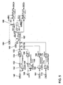
- a horizontal axis 10 The actual speed 12 of the internal combustion engine, the model speed 14, a controller output 16 for changing the ignition angle, so that an engine torque is changed accordingly, a controller output 18 for changing the cylinder charge, so that a Engine torque is changed accordingly, a position 20 of an accelerator pedal, which is manually operated by a driver, a speed 22 of the motor vehicle, a bit 23 B_anf, which signals "Anfahrregler active", and a clutch bit 24.
- On the vertical axis 26 is a value for the controller output
- on the vertical axis 28 is a vehicle speed and on the vertical axis 30 an actual speed is plotted.
- the driver easily actuates the accelerator pedal 20, so that the actual speed 12 increases accordingly. Since not yet engaged, first corresponds to the actual speed 12 of the model speed 14. However, by increasing engagement by the driver, the actual speed eventually drops. Since the driver in the course of the accelerator pedal is not pressed more, the actual speed 12 falls faster than it would be after the model speed 14 most favorable. The result is a speed deviation in the form of a difference Between actual speed 12 and model speed 14. In other words, the engine torque for the current starting situation is too low for lack of appropriate operation of the accelerator pedal. This leads to a corresponding controller output 16 and 18 for a change in the ignition angle and the cylinder filling such that the engine torque is increased.
- Fig. 2 illustrates the structure of a starting controller according to the invention.
- This comprises a first means 32 for determining the model speed in dependence on a position of the accelerator pedal and for determining a speed deviation between the actual speed and the model speed from the speed model, a second means 34 for determining a controller output for changing an ignition angle and a cylinder filling in dependence the speed deviation such that the speed deviation is minimized, and third means 36 for determining an activation and deactivation time respectively for the controller output for ignition angle and cylinder filling of the second device in dependence on the speed deviation and a current vehicle speed.
- An exemplary structure and operation of these three devices 32, 34 and 36 will be described below with reference to Fig. 3 to 5 explained.
- Fig. 3 illustrates the operation of the first device 32.
- An input 38 receives a desired torque mifa_w of the driver according to a position of the accelerator pedal, an input 40 receives a loss torque mdverl_w, and in subtracter 42 these two torque values are subtracted from each other at a target torque miob_w in memory location 44.
- a PT1 -Filter 46 receives as input the target torque miobs_m and converts this into a model speed of the start-up controller nanmod_w in memory location 48.
- the PT1 filter 46 receives an initialization value (iv) 50, a gain K 52 and a time constant (T) 54, the Determination will be explained later.
- the actual rotational speed 12 of the internal combustion engine is subtracted from the model rotational speed nanmod_w and a speed deviation dnobs_w in the memory location 58 is thus obtained.
- This value of the speed deviation dnobs_w is output at 60 as the output value of the first device.
- the first device 32 further includes a so-called. Luenberg observers. For this purpose, from a quotient of speed to speed nvquot_w in memory location 62 via a characteristic curve KLOBP 64, a factor obsp_w in memory location 66 determined in multiplier 68 with speed deviation dnobs_w from memory location 58 is multiplied to a proportional component of torque change dmobp_w in memory location 70 and in subtractor 72 subtracted from the target torque miob_w 44, so that in memory location 74, a correspondingly modified setpoint torque miobs_w as input for the PT1 filter 46 is available.
- Luenberg observers For this purpose, from a quotient of speed to speed nvquot_w in memory location 62 via a characteristic curve KLOBP 64, a factor obsp_w in memory location 66 determined in multiplier 68 with speed deviation dnobs_w from memory location 58 is multiplied to a proportional component of torque change dmo
- the Luenberger observer is also supplemented by an integral part.
- the speed deviation dnobs_w from memory location 58 is fed to an integrator 76, which converts the speed deviation dnobs_w into an integral portion of the torque change dmbi_w in memory location 78.
- This integral component of the torque change dmobi_w is added in adder 80 to the proportional component of the torque change dmobp_w in memory location 70, so that a torque change with proportional component and integral component dmobpi_w in memory location 82 is obtained.
- the integral component dmobi_w 78 flows into the subtraction at subtracter 72.
- a value obsk_w in memory location 86 is determined via a characteristic curve KLOBK 84 and fed to the integrator 76 as an input value for the gain K 88. Further, the integrator 76 receives an initialization value (iv) 90. In a block 92, the initialization of the PT1 filter 46 and integrator 76 is triggered on certain conditions, as will be described later. The integrator 76 always receives the initialization value 0. The initialization value 50 for the PT1 filter 46 is determined in a block 94 in dependence on the progress of the startup, as will also be described later.
- the input value for the gain K 52 for the PT1 filter 46 is determined from the quotient of speed to speed nvquot_w in memory location 62 by means of a characteristic KLPLK 96.
- the input value T 64 (Time constant) for the PT1 filter 46 is determined from the quotient of speed to speed nvquot_w in memory location 62 by means of a characteristic KLPLT 98 and written in memory location 100 as a value obst_w.
- the third device 36 receives as input values at 102 the instantaneous vehicle speed vfzg_w and at 104 the speed deviation dnobs_w from the first device. With these and possibly further values, the third device 36 determines whether switch-on conditions for the starting controller according to the invention are met and activates or deactivates the change of the ignition angle or the cylinder charge for controlling the torque output by the engine. The influence on the ignition angle or the cylinder filling is activated or deactivated separately. At an AND gate 106, different conditions must be met simultaneously, then a bit for "approach controller active with ignition angle adjustment" B_anf set and output at the output point 108.
- the polled conditions in the illustrated example include: The vehicle speed from the input 102 must be greater than a predetermined value VFZGMAX in memory location 110; a bit B_II 112 for the condition "idle” must not be set; a bit B_mdein 114 for the condition "torque intervention active" must not be set; an error bit for the speed E_n 116 must not be set; an error bit for the vehicle speed E_vfz 118 must not be set. Furthermore, in a block 120, a clutch bit and plausibility check is performed, the result of which must arrive positive in the AND gate 106.
- a bit for "Approach controller active without cylinder fill change" B_anol or a bit for "Approach controller active with cylinder fill change” B_anfl is set and output at output points 124, 126.
- the selection as to whether the bit B_anfl or B_anol is set is carried out as follows: When the bit B_anf is set for the first time, the input S is activated in a FLIPFLOP 130. Subsequently, the output Q is set high and an AND gate 132 switches the bit B_anfl to the output 124. At another AND gate 122 various other conditions are queried.
- These queried conditions in the illustrated example include: The vehicle speed from the input 102 must be greater than zero; the speed deviation from the input 104 must be less than a predetermined value DNMOTAB in memory location 128; the bit for "Anfahrregler active with ignition angle adjustment B_anf "must be set, in other words:
- the reset input R of the FLIPFLOP 130 is set in the area of the first intersection point (134 in Fig. 1 ) of model speed 14 and actual speed 12 (speed deviation near zero) activated. Then, the output Q of the FLIPFLOP 130 becomes “low”, the output of the AND gate 132 becomes “low”, thereby turning on another AND gate 138 because of the negation 136, and outputting the B_anol bit at the output 126.
- startup is divided into two phases, before point 144 (first phase) and after point 144 (second phase).
- first phase the starting controller influences the engine torque via the ignition angle (ignition path, rapid reaction of the torque) and the cylinder filling (air path, slow reaction of the torque).
- second phase of the Anfahrregler takes only a change of the ignition angle on the engine torque influence.
- a reset is made at the start of the startup process when B_anf is set for the first time.
- initialization value 50 for the PT1 filter 46 the instantaneous actual speed 12 of the internal combustion engine is determined in block 94.
- the transition to the second phase ie shortly after the intersection 134 ( Fig. 1 )
- initialization value 50 for the PT1 filter 46 by means of the switch 140 calculates a value from the content FNIBINI of the storage location 142, from the speed deviation dnobs_w from the storage location 58, and from the model speed nanmod_w from the storage location 48. This explains in Fig. 1 the jump of the model speed 14 at point 144.
- Fig. 5 Finally shows the actual controller 34, which determines from the speed deviation dnobs_w at input 146 and the change of the actual speed dnmot_w in memory 148, the controller output for the torque change by influencing the cylinder charge dmanl_w and the torque change by influencing the ignition dman_w.
- a factor as a function of dnobs_w is determined from a characteristic KLANFP 150 and multiplied in multiplier 152 by dnobs_w to a proportional component of the controller output dmanp_w in memory location 154.
- a characteristic KLANFD 156 becomes a factor as a function of dnmot_w is determined and multiplied in multiplier 158 by dnmot_w to a differential component of the controller output dmand_w in memory location 160.
- these proportional and integral components are combined from memory locations 154, 160.
- a factor fanfn in the memory location 168 is calculated via a characteristic KLANFN 166, with which the controller output is masked out with increasing actual speed via the multiplier 170.
- a factor fanfv in the memory location 176 is calculated via a characteristic KLANFV 174, with which the controller output is masked out as the vehicle speed increases via the multiplier 178.
- the controller outputs dmanl_w and dman_w are limited in their respective maximum and minimum values. Via the input 180 and switch 182, the control is activated only when the bit B_anf is set. Through the input 184 and the switch 186, the control of the cylinder filling is activated only when the bit B_anfl is set.
- the Anfahrregler invention reduces a drop in the actual speed 12 during the starting process and suppresses vibrations during the starting process (Antiruckelregelung). However, this vibration suppression can also be activated during a gear change.
- the recognition of which gear is currently engaged takes place via the quotient of speed to speed nvquot_w in memory location 62 (FIG. Fig. 3 ).
- the actual speed or engine speed 12 naturally breaks during engagement as a result of the additional clutch torque. The height of the break depends on the dynamics of the engagement and the speed level at the beginning of the process.
- the Anfahrregler specifically counteracts this speed drop by influencing the torque output by the engine.
- the Anfahrregler satisfies the various requirements for smoothness, efficiency, plausibility and cost-effectiveness and only intervenes to assist the driver the startup or a gear change.
- a model speed is determined from the speed model (PT1 filter 46) based on the driver's desired torque. From the difference of model speed and engine speed of the starting or a gear change is identified. If this is done, the driver's desired torque is increased accordingly.
- An essential advantage of the starting controller according to the invention lies in the strict separation of interventions in the torque balance on the faster ignition path (ignition angle change) on the one hand and on the slower filling path (Cylinder charge change) on the other hand.
- ignition angle change ignition angle change
- Cylinder charge change Cylinder charge change
- the model speed nanmod_w 48 is calculated from a relatively slow first-order delay element (PT1 filter 46).
- the second phase does not start exactly at the intersection 134 but a little later because in memory location 128 (FIG. Fig. 4 ) a negative value not equal to zero is entered. This determines the point 144 ( Fig. 1 ).
- the various characteristics mentioned serve to tune the speed model to the real conditions.
Landscapes
- Engineering & Computer Science (AREA)
- Mechanical Engineering (AREA)
- Chemical & Material Sciences (AREA)
- Combustion & Propulsion (AREA)
- Transportation (AREA)
- General Engineering & Computer Science (AREA)
- Automation & Control Theory (AREA)
- Theoretical Computer Science (AREA)
- Signal Processing (AREA)
- Combined Controls Of Internal Combustion Engines (AREA)
- Electrical Control Of Air Or Fuel Supplied To Internal-Combustion Engine (AREA)
Description
- Die Erfindung betrifft ein Verfahren zum Betreiben einer Brennkraftmaschine eines Kraftfahrzeuges gemäß dem Oberbegriff des Anspruchs 1 sowie einen Anfahrregler gemäß Anspruch 17.
- Beim manuellem Anfahren eines Kraftfahrzeuges muß ein Fahrer die Betätigung von Fahrpedal und Kupplungspedal genau abstimmen, um ein weiches und ruckelfreies Anfahren zu erzielen. Dies gelingt jedoch nicht immer in der gewünschten Weise. In Extremfällen betätigt der Fahrer das Gaspedal zu wenig und läßt die Kupplung zu schnell kommen, dann wird wegen des großen Trägheitsmomentes des Kraftfahrzeuges und des zu geringen Antriebsmomentes des Motors dieser abgewürgt oder es kommt zu einem ruckartigen Anfahren. Andererseits führt ein zu starkes Betätigen des Gaspedals zu einem unerwünschten Aufheulen des Motors.
- Aus der
EP 0 930 424 A2 ist ein Verfahren und eine Vorrichtung zur Verbesserung des Anfahrverhaltens eines Kraftfahrzeuges bekannt, wobei in einem Drehzahlmodell eine Drehzahl der Brennkraftmaschine in Abhängigkeit von einer Stellung eines Fahrpedales und/oder anderen Parametern des Kraftfahrzeuges als Modelldrehzahl nachgebildet wird und eine Drehzahlabweichung zwischen einer Ist-Drehzahl und der Modell-Drehzahl aus dem Drehzahlmodell bestimmt wird, wobei in Abhängigkeit von dieser Drehzahlabweichung ein Zündwinkel und/oder eine Zylinderfüllung derart beeinflusst wird, daß die Drehzahlabweichung minimiert wird. - Aus der
DE 198 02 217 A1 ist ein Verfahren zum ermittler des Fahrzeugantriebsmomentes beim Anfahren eines Fahrzeuges bekannt. Hierbei erfolgt ein modellbasiertes Ermitteln des Leerlaufverhaltens des Motors, vergleichen von Modellausgangswerten mit entsprechenden Messwerten oder davon abgeleiteten Werten und Ermitteln des Fahrzeugantriebsmomentes nach Maßgabe des vorher durchgeführten Vergleiches. - Aus der
EP 1 079 089 A2 ist eine Steuereinrichtung für eine Brennkraftmaschine bekannt, welche beim Starten der Brennkraftmaschine für die Kontrolle der Drehzahl den Einlassluftstrom kontrolliert. Hierbei wird eine Drosselklappe in Abhängigkeit der Motordrehzahl eingestellt. In Abhängigkeit einer Differenz zwischen einer vorbestimmten maximalen Motordrehzahl und der aktuellen Motordrehzahl wird von der Einlassluftkontrollsteuerung auf eine Zündwinkelsteuerung umgeschaltet. - Aus der
DE 196 49 424 A1 ist eine Drehmomentenabschätzung für eine Motorgeschwindigkeitssteuerung bekannt. Hierbei wird die Motordrehzahl mittels Eingriff in die Zündungssteuerung auf eine erwünschte Referenz-Motordrehzahl eingeregelt. - Der Erfindung liegt die Aufgabe zugrunde, einen Verfahren und einen Anfahrregler der obengenannten Art zur Verfügung zu stellen, welches den Fahrer gezielt beim Anfahren unterstützt.
- Diese Aufgabe wird erfindungsgemäß durch ein Verfahren der o.g. Art mit den in Anspruch 1 gekennzeichneten Merkmalen und durch einen Anfahrregler gemäß Anspruch 17 gelöst. Vorteilhafte Ausgestaltungen der Erfindung sind in den abhängigen Ansprüchen angegeben.
- Dazu ist es bei einem Verfahren der o.g. Art erfindungsgemäß vorgesehen, daß in einem Drehzahlmodell eine Drehzahl der Brennkraftmaschine in Abhängigkeit von einer Stellung eines Fahrpedals und/oder anderen Parametern des Kraftfahrzeuges als Modelldrehzahl nachgebildet und eine Drehzahlabweichung zwischen einer Istdrehzahl und der Modelldrehzahl aus dem Drehzahlmodell bestimmt wird, wobei in Abhängigkeit von der Drehzahlabweichung ein Zündwinkel und/oder eine Zylinderfüllung derart beeinflusst wird, wobei die Drehzahlabweichung minimiert wird. Mit dem Ausdruck "beeinflusst" ist hierbei eine Regelung eines Änderungsbetrages für Zylinderfüllung bzw. Zündwinkel gemeint, wobei der Änderungsbetrag zu einem Wert für Zündwinkel bzw.
- Einstellwerten für die Zylinderfüllung hinzugefügt wird, d.h. es wird beispielsweise ein von anderer Seite vorgegebener Zündwinkel um einen bestimmten Betrag verändert. Zusätzlich wird die Regelung des Zündwinkels und/oder der Zylinderfüllung in Abhängigkeit von einer Motordrehzahl und/oder einer Fahrzeuggeschwindigkeit ausgeblendet.
- Dies hat den Vorteil, daß für den Fahrer ein Regler zur Verfügung steht, welcher den Fahrer beim Anfahren unabhängig vom gewählten oder eingelegten Gang zum Erzielen eines ruckelfreien Übergangs unterstützt.
- In besonders vorteilhafter Weise wird die Beeinflussung während eines Anfahrens des Kraftfahrzeuges aus dem Stillstand durchgeführt. Hierdurch steht dem Fahrer ein Anfahrregler zur Verfügung, welcher ihn zum Erzielen eines weichen und ruckelfreien Anfahrens unterstützt. Nach Beginn des Anfahrens wird in einer ersten Phase der Zündwinkel und die Zylinderfüllung beeinflußt, wobei nach einem ersten Nulldurchgang der Drehzahlabweichung und wenn eine Geschwindigkeit des Fahrzeuges größer als ein vorbestimmter Wert ist, nur noch der Zündwinkel beeinflußt wird.
- Um ein Entgegenwirken von einer Leerlaufregelung und der Beeinflussung des Zündwinkels zu verhindern, wird die Beeinflussung des Zündwinkels ausgesetzt, wenn die Leerlaufregelung in entgegengesetzter Richtung zum Anfahrregler Drehmomente anhebend eingreift.
- In einer bevorzugten Ausführungsform wird in dem Drehzahlmodell ein Solldrehmoment über ein PT1-Filter in die Modelldrehzahl umgewandelt, wobei das Solldrehmoment aus einem Wunschdrehmoment des Fahrers gemäß einer Stellung des Fahrpedals abzüglich eines Verlustdrehmomentes bestimmt wird. Die Drehzahlabweichung wird dabei dadurch bestimmt, daß von der Modelldrehzahl die Istdrehzahl abgezogen wird.
- Ein Luenberger-Beobachter wird dadurch eingeführt, daß aus einem Quotienten von Istdrehzahl zu Geschwindigkeit des Kraftfahrzeugs über eine Kennlinie ein Faktor bestimmt und mit der Drehzahlabweichung zu einem Proportionalanteil einer Drehmomentänderung multipliziert wird, daß aus der Drehzahlabweichung über einen Integrator ein Integralanteil der Drehmomentänderung bestimmt wird, und daß eine Summe aus Proportionalanteil und Integralanteil der Drehmomentänderung von dem Solldrehmoment vor dem Eingang in das PT1-Filter abgezogen wird.
- Zur dynamischen Anpassung des Integrators sowie zur Abstimmung des Drehzahlmodells wird aus dem Quotienten von Istdrehzahl zu Geschwindigkeit des Kraftfahrzeugs über eine Kennlinie eine Verstärkung als Eingangswert für den Integrator bestimmt.
- Zur dynamischen Anpassung des PT1-Filters sowie zur Abstimmung des Drehzahlmodells werden aus dem Quotienten von Istdrehzahl zu Geschwindigkeit des Kraftfahrzeugs über eine jeweilige Kennlinie eine Verstärkung sowie eine Zeitkonstante als Eingangswerte für das PT1-Filter bestimmt.
- Um sicher zu stellen, daß die Beeinflussung bei vorbestimmten Betriebszuständen des Kraftfahrzeuges einsetzt, wird aus wenigstens einem vorbestimmten, das Kraftfahrzeug betreffenden Wert eine Einschaltbedingung für die Beeinflussung des Zündzeitpunktes und der Zylinderfüllung bestimmt. Der wenigstens eine vorbestimmte Wert umfaßt beispielsweise einen Fehlerwert aus der Bestimmung der Fahrzeuggeschwindigkeit, einen Fehlerwert aus der Bestimmung der Motordrehzahl, ein Leerlauf-Bit, eine Bedingung "Momenteneingriff aktiv" und/oder eine Fahrzeuggeschwindigkeit.
- Die Bestimmung eines Regelwertes für die Änderung von Zündwinkel und Zylinderfüllung erfolgt derart, daß der Wert der Drehzahlabweichung mit einem Wert aus einer Kennlinie entsprechend der Drehzahlabweichung zu einem Proportionalanteil einer notwendigen Drehmomentänderung multipliziert wird, daß ein Wert einer Änderung der Istdrehzahl mit einem Wert aus einer Kennlinie entsprechend der Änderung der Istdrehzahl zu einem Differentialanteil einer notwendigen Drehmomentänderung multipliziert wird und daß Proportionalanteil und Differentialanteil der Drehmomentänderung zu einem Reglerausgang für den Zündwinkel und/oder die Zylinderfüllung addiert werden. Der Reglerausgang wird in seinem maximalen und minimalen Wert begrenzt. Der Reglerausgang für die Zylinderfüllung wird mit einem vorbestimmten Faktor multipliziert.
- Ferner wird erfindungsgemäß ein Anfahrregler für eine Brennkraftmaschine eines Kraftfahrzeuges vorgeschlagen mit einer ersten Einrichtung zum Nachbilden einer Drehzahl der Brennkraftmaschine in Abhängigkeit von einer Stellung eines Fahrpedals als Modelldrehzahl mittels eines Drehzahlmodells und zum Bestimmen einer Drehzahlabweichung zwischen einer Istdrehzahl und der Modelldrehzahl aus dem Drehzahlmodell, mit einer zweiten Einrichtung zum Bestimmen eines Reglerausgangs zum Beeinflussen des Zündwinkels und der Zylinderfüllung in Abhängigkeit von der Drehzahlabweichung derart, daß die Drehzahlabweichung minimiert ist, wobei die erste Einrichtung zum Ausbilden des Drehzahlmodelles einen PT1-Filter umfasst, der einen Solldrehmoment in die Modelldrehzahl umwandelt und wobei die erste Einrichtung einen integrator umfasst, der einen Integralanteil der Drehzahlabweichung auf das Solldrehmoment rückkoppelt.
- Dies hat den Vorteil, daß für den Fahrer ein Regler zur Verfügung steht, welcher den Fahrer beim Anfahren unabhängig vom gewählten oder eingelegten Gang zum Erzielen eines ruckelfreien Übergangs unterstützt.
- Zum Sicherstellen einer Regelung nur bei bestimmten Betriebszuständen ist eine dritte Einrichtung zum Bestimmen eines Aktivierungs- und Deaktivierungszeitpunktes jeweils für den Reglerausgang zum Beeinflussen des Zündwinkels und der Zylinderfüllung der zweiten Einrichtung in Abhängigkeit von der Drehzahlabweichung und einer momentanen Fahrzeuggeschwindigkeit vorgesehen.
- Die erste Einrichtung umfaßt dabei zusätzlich einen Luenberger-Beobachter, der einen Proportionalanteil der Drehzahlabweichung auf das Solldrehmoment rückkoppelt.
- Weitere Merkmale, Vorteile und vorteilhafte Ausgestaltungen der Erfindung ergeben sich aus den abhängigen Ansprüchen, sowie aus der nachstehenden Beschreibung der Erfindung anhand der beigefügten Zeichnungen. Diese zeigen in
- Fig. 1
- eine graphische Veranschaulichung des erfindungsgemäßen Verfahrens als Anfahrregler,
- Fig. 2
- ein schematisches Blockschaltbild eines erfindungsgemäßen Anfahrreglers,
- Fig. 3
- ein schematisches Funktionsdiagramm einer ersten Einrichtung mit Drehzahlmodell und mit Luenberger-Beobachter des Anfahrreglers gemäß
Fig. 2 , - Fig. 4
- ein schematisches Funktionsdiagramm einer dritten Einrichtung zum Aktivieren bzw. Deaktivieren der Regelung des Anfahrreglers gemäß
Fig. 2 und - Fig. 5
- ein schematisches Funktionsdiagramm einer zweiten Einrichtung (Reglereinrichtung) des Anfahrreglers gemäß
Fig. 2 . - Bei dem erfindungsgemäßen Verfahren zum Betreiben einer Brennkraftmaschine eines Kraftfahrzeuges wird in einem Drehzahlmodell eine Drehzahl der Brennkraftmaschine in Abhängigkeit von einer Stellung eines Fahrpedals als Modelldrehzahl nachgebildet und eine Drehzahlabweichung zwischen einer Istdrehzahl und der Modelldrehzahl aus dem Drehzahlmodell bestimmt. Dann wird in Abhängigkeit von der Drehzahlabweichung ein Zündwinkel und/oder eine Zylinderfüllung derart beeinflußt, daß die Drehzahlabweichung minimiert wird. Dies wird nachfolgend anhand von
Fig. 1 näher erläutert, die das erfindungsgemäße Verfahren bei der Funktion eines Anfahrreglers veranschaulicht. Hierzu ist über die Zeit auf einer horizontalen Achse 10 folgendes aufgetragen: Die Istdrehzahl 12 der Brennkraftmaschine, die Modelldrehzahl 14, ein Reglerausgang 16 zum Ändern des Zündwinkels, so daß ein Motormoment entsprechend geändert wird, ein Reglerausgang 18 zum Ändern der Zylinderfüllung, so daß ein Motormoment entsprechend geändert wird, eine Stellung 20 eines Fahrpedals, welches von einem Fahrer manuell betätigt wird, eine Geschwindigkeit 22 des Kraftfahrzeuges, ein Bit 23 B_anf, welches "Anfahrregler aktiv" signalisiert, und ein Kupplungsbit 24. Auf der vertikalen Achse 26 ist ein Wert für den Reglerausgang, auf der vertikalen Achse 28 ist eine Fahrzeuggeschwindigkeit und auf der vertikalen Achse 30 ist eine Istdrehzahl aufgetragen. - Der Fahrer betätigt leicht das Fahrpedal 20, so daß die Istdrehzahl 12 entsprechend ansteigt. Da noch nicht eingekuppelt ist, entspricht zunächst die Istdrehzahl 12 der Modelldrehzahl 14. Durch zunehmendes Einkuppeln seitens des Fahrers fällt jedoch die Istdrehzahl schließlich ab. Da der Fahrer im weiteren Verlauf das Fahrpedal nicht stärker betätigt, fällt die Istdrehzahl 12 schneller als es nach der Modelldrehzahl 14 am günstigsten wäre. Es entsteht eine Drehzahlabweichung in Form einer Differenz zwischen Istdrehzahl 12 und Modelldrehzahl 14. Mit anderem Worten ist das Motormoment für die momentane Anfahrsituation mangels entsprechender Betätigung des Fahrpedals zu niedrig. Dies führt zu einem entsprechenden Reglerausgang 16 und 18 für eine Änderung des Zündwinkels und der Zylinderfüllung derart, daß das Motormoment erhöht wird. In der Folge reduziert sich der Abstand zwischen der Istdrehzahl 12 und der Modelldrehzahl 14 (Drehzahlabweichung wird im Betrag kleiner) bis sich die Graphen für die Istdrehzahl 12 und die Modelldrehzahl 14 treffen. Zu diesem Zeitpunkt wird die Regelung über die Zylinderfüllung (Graph 18) beendet und nur noch der Zündwinkel geändert, so daß die Differenz zwischen der Istdrehzahl 12 und der Modelldrehzahl 14 (Drehzahlabweichung) minimal wird. Mit zunehmender Geschwindigkeit 22 des Kraftfahrzeuges und zunehmender Istdrehzahl 12 der Brennkraftmaschine wird dann auch die Beeinflussung des Zündwinkels (Graph 16) weich ausgeblendet.
-
Fig. 2 veranschaulicht den Aufbau eines erfindungsgemäßen Anfahrreglers. Dieser umfaßt eine erste Einrichtung 32 zum Bestimmen der Modelldrehzahl in Abhängigkeit von einer Stellung des Fahrpedals und zum Bestimmen einer Drehzahlabweichung zwischen der Istdrehzahl und der Modelldrehzahl aus dem Drehzahlmodell, eine zweiten Einrichtung 34 zum Bestimmen eines Reglerausgangs zum Ändern eines Zündwinkels und einer Zylinderfüllung in Abhängigkeit von der Drehzahlabweichung derart, daß die Drehzahlabweichung minimiert ist, und eine dritte Einrichtung 36 zum Bestimmen eines Aktivierungs- und Deaktivierungszeitpunktes jeweils für den Reglerausgang für Zündwinkel und Zylinderfüllung der zweiten Einrichtung in Abhängigkeit von der Drehzahlabweichung und einer momentanen Fahrzeuggeschwindigkeit. Ein beispielhafter Aufbau und eine Funktionsweise dieser drei Einrichtungen 32, 34 sowie 36 wird nachfolgend anhand derFig. 3 bis 5 erläutert. -
Fig. 3 veranschaulicht die Funktionsweise der ersten Einrichtung 32. Ein Eingang 38 erhält ein Wunschdrehmoment mifa_w des Fahrers gemäß einer Stellung des Fahrpedals, ein Eingang 40 erhält ein Verlustdrehmoment mdverl_w und in Subtrahierer 42 werden diese beiden Drehmomentwerte voneinander abgezogen zu einem Solldrehmoment miob_w in Speicherstelle 44. Ein PT1-Filter 46 erhält als Eingang das Solldrehmoment miobs_m und setzt dieses in eine Modelldrehzahl des Anfahrreglers nanmod_w in Speicherstelle 48 um. Hierzu erhält das PT1-Filter 46 einen Initialisierungswert (iv) 50, eine Verstärkung K 52 und eine Zeitkonstante (T) 54, deren Bestimmung später erläutert wird. Im Subtrahierer 56 wird von der Modelldrehzahl nanmod_w die Istdrehzahl 12 der Brennkraftmaschine abgezogen und so eine Drehzahlabweichung dnobs_w in Speicherstelle 58 erhalten. Dieser Wert der Drehzahlabweichung dnobs_w wird bei 60 als Ausgangswert der ersten Einrichtung ausgegeben. - Neben dem Drehzahlmodell des PT1-Filters 46 enthält die erste Einrichtung 32 ferner einen sogen. Luenberger-Beobachter. Hierzu wird aus einem Quotienten von Drehzahl zu Geschwindigkeit nvquot_w in Speicherstelle 62 über eine Kennlinie KLOBP 64 ein Faktor obsp_w in Speicherstelle 66 bestimmt in einem Multiplizierer 68 mit der Drehzahlabweichung dnobs_w aus Speicherstelle 58 zu einem Proportionalanteil der Drehmomentänderung dmobp_w in Speicherstelle 70 multipliziert und im Subtrahierer 72 von dem Solldrehmoment miob_w 44 abgezogen, so daß in Speicherstelle 74 ein entsprechend modifiziertes Solldrehmoment miobs_w als Eingang für das PT1-Filter 46 zur Verfügung steht.
- Der Luenberger-Beobachter ist ferner noch durch einen Integralanteil ergänzt. Hierzu wird die Drehzahlabweichung dnobs_w aus Speicherstelle 58 einem Integrator 76 zugeführt, der die Drehzahlabweichung dnobs_w in einen Integralanteil der Drehmomentänderung dmbi_w in Speicherstelle 78 umsetzt. Dieser Integralanteil der Drehmomentänderung dmobi_w wird in Addierer 80 zum Proportionalanteil der Drehmomentänderung dmobp_w in Speicherstelle 70 hinzuaddiert, so daß man eine Drehmomentänderung mit Proportionalanteil und Integralanteil dmobpi_w in Speicherstelle 82 erhält. Dadurch fließt in die Subtraktion bei Subtrahierer 72 der Integralanteil dmobi_w 78 mit ein. Aus dem Quotienten von Drehzahl zu Geschwindigkeit nvquot_w in Speicherstelle 62 wird über eine Kennlinie KLOBK 84 ein Wert obsk_w in Speicherstelle 86 bestimmt und als Eingangswert für die Verstärkung K 88 dem Integrator 76 zugeführt. Ferner erhält der Integrator 76 einen Initialisierungswert (iv) 90. In einem Block 92 wird die Initialisierung von PT1-Filter 46 und Integrator 76 zu bestimmten Bedingungen ausgelöst, wie noch später beschrieben wird. Der Integrator 76 erhält immer den Initialisierungswert 0. Der Initialisierungswert 50 für das PT1-Filter 46 wird in einem Block 94 in Abhängigkeit vom Fortschritt des Anfahrens bestimmt, wie ebenfalls später näher beschrieben wird. Der Eingangswert für die Verstärkung K 52 für das PT1-Filter 46 wird aus dem Quotienten von Drehzahl zu Geschwindigkeit nvquot_w in Speicherstelle 62 mittels einer Kennlinie KLPLK 96 bestimmt. Der Eingangswert T 64 (Zeitkonstante) für das PT1-Filter 46 wird aus dem Quotienten von Drehzahl zu Geschwindigkeit nvquot_w in Speicherstelle 62 mittels einer Kennlinie KLPLT 98 bestimmt und in Speicherstelle 100 als Wert obst_w geschrieben.
- Der Aufbau bzw. die Funktionsweise der dritten Einrichtung 36 wird nunmehr anhand der
Fig. 4 beschrieben. Die dritte Einrichtung 36 erhält als Eingangswerte bei 102 die momentane Fahrzeuggeschwindigkeit vfzg_w und bei 104 die Drehzahlabweichung dnobs_w aus der ersten Einrichtung. Mit diesen und ggf. weiteren Werten bestimmt die dritte Einrichtung 36, ob Einschaltbedingungen für den erfindungsgemäßen Anfahrregler erfüllt sind und aktiviert bzw. deaktiviert die Änderung des Zündwinkels bzw. der Zylinderfüllung zur Regelung des vom Motor abgegebenen Drehmomentes. Die Einflußnahme auf den Zündwinkel bzw. die Zylinderfüllung wird dabei getrennt aktiviert bzw. deaktiviert. An einem UND-Gatter 106 müssen verschiedene Bedingungen gleichzeitig erfüllt sein, dann wird ein Bit für "Anfahrregler aktiv mit Zündwinkelverstellung" B_anf gesetzt und an der Ausgabestelle 108 ausgegeben. Die abgefragten Bedingungen umfassen in dem dargestellten Beispiel folgendes: Die Fahrzeuggeschwindigkeit aus dem Eingang 102 muß größer sein als ein vorbestimmter Wert VFZGMAX in Speicherstelle 110; ein Bit B_II 112 für die Bedingung "Leerlauf" darf nicht gesetzt sein; ein Bit B_mdein 114 für die Bedingung "Momenteneingriff aktiv" darf nicht gesetzt sein; ein Fehlerbit für die Drehzahl E_n 116 darf nicht gesetzt sein; ein Fehlerbit für die Fahrzeuggeschwindigkeit E_vfz 118 darf nicht gesetzt sein. Ferner erfolgt in einem Block 120 eine Kupplungsbit- und Plausibilitätsprüfung, dessen Ergebnis positiv im UND-Gatter 106 ankommen muß. - In Abhängigkeit von weiteren Bedingungen wird wahlweise ein Bit für "Anfahrregler aktiv ohne Änderung Zylinderfüllung" B_anol oder ein Bit für "Anfahrregler aktiv mit Änderung Zylinderfüllung" B_anfl gesetzt und an den Ausgabestellen 124, 126 ausgegeben. Die Auswahl, ob das Bit B_anfl oder B_anol gesetzt wird erfolgt dabei folgendermaßen: Beim ersten Setzen des Bits B_anf wird in einem FLIPFLOP 130 der Seteingang S aktiviert. Daraufhin wird der Ausgang Q hoch gesetzt und ein UND-Gatter 132 schaltet das Bit B_anfl auf den Ausgang 124. An einem weiteren UND-Gatter 122 werden verschiedene weitere Bedingungen abgefragt. Diese abgefragten Bedingungen umfassen in dem dargestellten Beispiel folgendes: Die Fahrzeuggeschwindigkeit aus dem Eingang 102 muß größer als null sein; die Drehzahlabweichung aus dem Eingang 104 muß kleiner als ein vorbestimmter Wert DNMOTAB in Speicherstelle 128 sein; das Bit für "Anfahrregler aktiv mit Zündwinkelverstellung B_anf" muß gesetzt sein. Mit anderen Worten: Der Reseteingang R des FLIPFLOP 130 wird im Bereich des ersten Schnittpunktes (134 in
Fig. 1 ) von Modelldrehzahl 14 und Istdrehzahl 12 (Drehzahlabweichung nahe null) aktiviert. Dann wird der Ausgang Q des FLIPFLOP 130 "niedrig/low", der Ausgang des UND-Gatters 132 wird "niedrig/low", wodurch wegen der Negation 136 ein weiteres UND-Gatter 138 durchschaltet und das Bit B_anol am Ausgang 126 ausgibt. Gleichzeitig fällt das Bit B_anfl am Ausgang 124 weg. Dadurch ist das Anfahren in zwei Phasen geteilt, vor dem Punkt 144 (erste Phase) und nach dem Punkt 144 (zweite Phase). In der ersten Phase erfolgt eine Einflußnahme des Anfahrreglers auf das Motordrehmoment über den Zündwinkel (Zündpfad, schnelle Reaktion des Drehmomentes) und die Zylinderfüllung (Luftpfad, langsame Reaktion des Drehmomentes). In der zweiten Phase nimmt der Anfahrregler nur noch über eine Änderung des Zündwinkels auf das Motordrehmoment Einfluß. - Deswegen sind in Block 92 in
Fig. 3 zwei Bedingungen für einen Reset von PT1-Filter 46 und Integrator 76 vorgesehen. Zunächst erfolgt ein Reset am Beginn des Anfahrvorganges, wenn B_anf das erste mal gesetzt wird. Als Initialisierungswert 50 für das PT1-Filter 46 wird in Block 94 die momentane Istdrehzahl 12 der Brennkraftmaschine bestimmt. Beim Übergang in die zweite Phase, d.h. kurz nach dem Schnittpunkt 134 (Fig. 1 ), erfolgt wegen der positiven Flanke des Bits B_anol, d.h. wenn die Regelung des Luftpfades abgeworfen wird, eine erneute Initialisierung von PT1-Filter 46 und Integrator 76. Hierbei wird jedoch in Block 94 als Initialisierungswert 50 für das PT1-Filter 46 mittels des Schalters 140 ein Wert aus dem Inhalt FNIBINI der Speicherstelle 142, aus der Drehzahlabweichung dnobs_w aus der Speicherstelle 58 und aus der Modelldrehzahl nanmod_w aus der Speicherstelle 48 berechnet. Dies erklärt inFig. 1 den Sprung der Modelldrehzahl 14 am Punkt 144. -
Fig. 5 zeigt schließlich den eigentlichen Regler 34, der aus der Drehzahlabweichung dnobs_w am Eingang 146 und der Änderung der Istdrehzahl dnmot_w in Speicherstelle 148 den Reglerausgang für die Drehmomentänderung mittels Beeinflussung der Zylinderfüllung dmanl_w und die Drehmomentänderung mittels Beeinflussung des Zündzeitpunktes dman_w bestimmt. Hierzu wird aus einer Kennlinie KLANFP 150 ein Faktor in Abhängigkeit von dnobs_w ermittelt und im Multiplikator 152 mit dnobs_w zu einem Proportionalanteil des Reglerausgangs dmanp_w in Speicherstelle 154 multipliziert. Ferner wird aus einer Kennlinie KLANFD 156 ein Faktor in Abhängigkeit von dnmot_w ermittelt und im Multiplikator 158 mit dnmot_w zu einem Differentialanteil des Reglerausgangs dmand_w in Speicherstelle 160 multipliziert. Im Addierer 162 werden dieser Proportional- und Integralanteil aus den Speicherstellen 154, 160 zusammen geführt. Aus der Istdrehzahl nmot_w am Eingang 164 wird über eine Kennlinie KLANFN 166 ein Faktor fanfn in Speicherstelle 168 berechnet, mit dem über den Multiplikator 170 der Reglerausgang mit zunehmender Istdrehzahl ausgeblendet wird. Aus der Fahrzeuggeschwindigkeit vfzg_w am Eingang 172 wird über eine Kennlinie KLANFV 174 ein Faktor fanfv in Speicherstelle 176 berechnet, mit dem über den Multiplikator 178 der Reglerausgang mit zunehmender Fahrzeuggeschwindigkeit ausgeblendet wird. Die Reglerausgänge dmanl_w und dman_w werden in ihrem jeweiligen Maximal- und Minimalwert begrenzt. Über den Eingang 180 und Schalter 182 wird die Regelung nur aktiviert, wenn das Bit B_anf gesetzt ist. Über den Eingang 184 und den Schalter 186 wird die Regelung der Zylinderfüllung nur aktiviert, wenn das Bit B_anfl gesetzt ist. - Der Erfindungsgemäße Anfahrregler verringert ein Absinken der Istdrehzahl 12 beim Anfahrvorgang und unterdrückt Schwingungen beim Anfahrvorgang (Antiruckelregelung). Diese Schwingungsunterdrückung kann jedoch auch bei einem Gangwechsel aktiviert werden. Die Erkennung, welcher Gang gerade eingelegt ist erfolgt dabei über den Quotienten aus Drehzahl zu Geschwindigkeit nvquot_w in Speicherstelle 62 (
Fig. 3 ). Bei einem typischen Anfahrvorgang bricht die Istdrehzahl bzw. Motordrehzahl 12 während des Einkuppelns naturgemäß als Folge des zusätzlichen Kupplungsmomentes ein. Die Höhe des Einbruches hängt von der Dynamik des Einkuppelns und vom Drehzahlniveau zu Beginn des Vorganges ab. Der Anfahrregler wirkt diesem Drehzahleinbruch durch Einflußnahme auf das vom Motor abgegebene Drehmoment gezielt entgegen. Der Anfahrregler genügt dabei den verschiedenen Forderungen nach Laufruhe, Wirksamkeit, Plausibilität sowie Wirtschaftlichkeit und greift lediglich unterstützend ein, um dem Fahrer den Anfahrvorgang oder einen Gangwechsel zu erleichtern. Hierzu wird aus dem Drehzahlmodell (PT1-Filter 46) auf Basis des Fahrerwunschmomentes eine Modelldrehzahl ermittelt. Aus der Differenz von Modelldrehzahl und Motordrehzahl wird der Anfahrvorgang oder ein Gangwechsel identifiziert. Ist dies geschehen, so wird das Fahrerwunschmoment entsprechend angehoben. - Ein wesentlicher Vorteil des erfindungsgemäßen Anfahrreglers liegt in der strikten Trennung von Eingriffen in die Momentenbilanz auf dem schnelleren Zündungspfad (Zündwinkeländerung) einerseits und auf dem langsameren Füllungspfad (Zylinderfüllungsänderung) andererseits. Während des eigentlichen Anfahr- oder Schaltvorgangs (erste Phase) mit einbrechender Motordrehzahl ist sowohl der schnelle als auch der langsame Eingriff aktiv. Die anschließenden Schwingungen im Antriebsstrang in der zweiten Phase werden nur noch durch Eingriffe auf dem schnelleren Zündungspfad bedämpft.
- Die Modelldrehzahl nanmod_w 48 wird aus einem relativ langsamen Verzögerungsglied 1. Ordnung (PT1-Filter 46) berechnet. Die zweite Phase beginnt nicht genau am Schnittpunkt 134 sondern etwas später, weil in Speicherstelle 128 (
Fig. 4 ) ein negativer Wert ungleich null eingetragen ist. Dieser bestimmt den Punkt 144 (Fig. 1 ). Die verschiedenen erwähnten Kennlinien dienen zum Abstimmen des Drehzahlmodells auf die realen Gegebenheiten.
Claims (19)
- Verfahren zum Betreiben einer Brennkraftmaschine eines Kraftfahrzeuges wobei in einem Drehzahlmodell eine Drehzahl der Brennkraftmaschine in Abhängigkeit von einer Stellung eines Fahrpedals und/oder anderen Parametern des Kraftfahrzeuges als Modelldrehzahl nachgebildet und eine Drehzahlabweichung zwischen einer Istdrehzahl und der Modelldrehzahl aus dem Drehzahlmodell bestimmt wird, wobei in Abhängigkeit von der Drehzahlabweichung ein Zündwinkel und/oder eine Zylinderfüllung derart beeinflußt wird, daß die Drehzahlabweichung minimiert wird,
dadurch gekennzeichnet, dass die Regelung von Zündwinkel und/oder Zylinderfüllung in Abhängigkeit von einer Motordrehzahl und/oder einer Fahrzeuggeschwindigkeit ausgeblendet wird. - Verfahren nach Anspruch 1, dadurch gekennzeichnet, daß die Beeinflussung während eines Anfahrens des Kraftfahrzeuges aus dem Stillstand durchgeführt wird.
- Verfahren nach Anspruch 2, dadurch gekennzeichnet, daß nach Beginn des Anfahrens in einer ersten Phase der Zündwinkel und die Zylinderfüllung beeinflußt wird, wobei nach einem ersten Nulldurchgang der Drehzahlabweichung und wenn eine Geschwindigkeit des Fahrzeuges größer als ein vorbestimmter Wert ist, nur noch der Zündwinkel beeinflußt wird.
- Verfahren nach wenigstens einem der vorhergehenden Ansprüche, dadurch gekennzeichnet, daß die Beeinflussung des Zündwinkels ausgesetzt wird, wenn die Leerlaufregelung in entgegengesetzter Richtung zur Beeinflussung des Zündwinkels Drehmomente anhebend eingreift.
- Verfahren nach wenigstens einem der vorhergehenden Ansprüche, dadurch gekennzeichnet, daß in dem Drehzahlmodell ein Solldrehmoment über ein PT1-Filter in die Modelldrehzahl umgewandelt wird.
- Verfahren nach Anspruch 5, dadurch gekennzeichnet, daß das Solldrehmoment aus einem Wunschdrehmoment des Fahrers gemäß einer Stellung des Fahrpedals abzüglich eines Verlustdrehmomentes bestimmt wird.
- Verfahren nach Anspruch 5 oder 6, dadurch gekennzeichnet, daß die Drehzahlabweichung dadurch bestimmt wird, daß von der Modelldrehzahl die Istdrehzahl abgezogen wird.
- Verfahren nach wenigstens einem der Ansprüche 5 bis 7, dadurch gekennzelchhet, daß aus einem Quotienten von Istdrehzahl zu Geschwindigkeit des Kraftfahrzeugs über eine Kennlinie ein Faktor bestimmt und mit der Drehzahlabweichung zu einem Proportionalanteil einer Drehmomentänderung multipliziert wird, daß aus der Drehzahlabweichung über einen Integrator ein Integralanteil der Drehmomentänderung bestimmt wird, und daß eine Summe aus Proportionalanteil und Integralanteil der Drehmomentänderung von dem Solldrehmoment vor dem Eingang in das PT1-Filter abgezogen wird.
- Verfahren nach Anspruch 8, dadurch gekennzeichnet, daß aus dem Quotienten von Istdrehzahl zu Geschwindigkeit des Kraftfahrzeugs über eine Kennlinie eine Verstärkung als Eingangswert für den Integrator bestimmt wird.
- Verfahren nach wenigstens einem der Ansprüche 5 bis 9, dadurch gekennzeichnet, daß aus dem Quotienten von Istdrehzahl zu Geschwindigkeit des Kraftfahrzeugs über eine Kennlinie eine Verstärkung als Eingangswert für das PT1-Filter bestimmt wird.
- Verfahren nach wenigstens einem der Ansprüche 5 bis 10, dadurch gekennzeichnet, daß aus dem Quotienten von Istdrehzahl zu Geschwindigkeit des Kraftfahrzeugs über eine Kennlinie eine Zeitkonstante als Eingangswert für das PT1-Filter bestimmt wird.
- Verfahren nach wenigstens einem der vorhergehenden Ansprüche, dadurch gekennzeichnet, daß aus wenigstens einem vorbestimmten, das Kraftfahrzeug betreffenden Wert eine Einschaltbedingung für die Beeinflussung des Zündzeitpunktes und der Zylinderfüllung bestimmt wird.
- Verfahren nach Anspruch 12, dadurch gekennzeichnet, daß der wenigstens eine vorbestimmte Wert einen Fehlerwert aus der Bestimmung der Fahrzeuggeschwindigkeit, einen Fehlerwert aus der Bestimmung der Motordrehzahl, ein Leerlauf-Bit, eine Bedingung "Momenteneingriff aktiv" und/oder eine Fahrzeuggeschwindigkeit umfaßt.
- Verfahren nach wenigstens einem der vorhergehenden Ansprüche, dadurch gekennzeichnet, daß der Wert der Drehzahlabweichung mit einem Wert aus einer Kennlinie entsprechend der Drehzahlabweichung zu einem Proportionalanteil einer notwendigen Drehmomentänderung multipliziert wird, daß ein Wert einer Änderung der Istdrehzahl mit einem Wert aus einer Kennlinie entsprechend der Änderung der Istdrehzahl zu einem Differentialanteil einer notwendigen Drehmomentänderung multipliziert wird und daß Proportionalanteil und Differentialanteil der Drehmomentänderung zu einem Reglerausgang für den Zündwinkel und/oder die Zylinderfüllung addiert werden.
- Verfahren nach Anspruch 14, dadurch gekennzeichnet, daß der Reglerausgang in seinem maximalen und minimalen Wert begrenzt wird.
- Verfahren nach Anspruch 14 oder 15, dadurch gekennzeichnet, daß der Reglerausgang für die Zylinderfüllung mit einem vorbestimmten Faktor multipliziert wird.
- Anfahrregler für eine Brennkraftmaschine eines Kraftfahrzeuges welcher zur Durchführung eines Verfahrens nach einem der Ansprüche 1 bis 16 ausgebildet ist, mit einer ersten Einrichtung (32) zum Nachbilden einer Drehzahl der Brennkraftmaschine in Abhängigkeit von einer Stellung eines Fahrpedals als Modelldrehzahl (14) mittels eines Drehzahlmodells (46) und zum Bestimmen einer Drehzahlabweichung (58) zwischen einer Istdrehzahl (12) und der Modelldrehzahl (14) aus dem Drehzahlmodell (46), mit einer zweiten Einrichtung (34) zum Bestimmen eines Reglerausgangs zum Beeinflussen des Zündwinkels und der Zylinderfüllung in Abhängigkeit von der Drehzahlabweichung (58) derart, daß die Drehzahlabweichung (58) minimiert ist, wobei die erste Einrichtung (32) zum Ausbilden des Drehzahlmodells einen PT1-Filter (46) umfaßt, der ein Solldrehmoment (74) in die Modelldrehzahl (14, 48) umwandelt, und wobei die erste Einrichtung (32) einen Integrator (76) umfaßt, der einen Integralanteil der Drehzahlabweichung (78) auf das Solldrehmoment (44) rückkoppelt.
- Anfahrregler nach Anspruch 17, dadurch gekennzelchnet, daß eine dritte Einrichtung (36) zum Bestimmen eines Aktivierungs- und Deaktivierungszeitpunktes jeweils für den Reglerausgang zum Beeinflussen des Zündwinkel und der Zylinderfüllung der zweiten Einrichtung (34) in Abhängigkeit von der Drehzahlabweichung (58) und einer momentanen Fahrzeuggeschwindigkeit (22) vorgesehen ist.
- Anfahrregler nach Anspruch 17, dadurch gekennzeichnet, daß die erste Einrichtung (32) einen Luenberger-Beobachter umfaßt, der einen Proportionalanteil der Drehzahlabweichung (70) auf das Solldrehmoment (44) rückkoppelt.
Applications Claiming Priority (2)
| Application Number | Priority Date | Filing Date | Title |
|---|---|---|---|
| DE10141003 | 2001-08-21 | ||
| DE10141003A DE10141003A1 (de) | 2001-08-21 | 2001-08-21 | Verfahren zum Betreiben einer Brennkraftmaschine sowie Anfahrregler für ein Kraftfahrzeug |
Publications (3)
| Publication Number | Publication Date |
|---|---|
| EP1286033A2 EP1286033A2 (de) | 2003-02-26 |
| EP1286033A3 EP1286033A3 (de) | 2008-10-29 |
| EP1286033B1 true EP1286033B1 (de) | 2013-05-22 |
Family
ID=7696157
Family Applications (1)
| Application Number | Title | Priority Date | Filing Date |
|---|---|---|---|
| EP02017006.4A Expired - Lifetime EP1286033B1 (de) | 2001-08-21 | 2002-07-27 | Verfahren zum Betreiben einer Brennkraftmaschine sowie Anfahrregler für ein Kraftfahrzeug |
Country Status (2)
| Country | Link |
|---|---|
| EP (1) | EP1286033B1 (de) |
| DE (1) | DE10141003A1 (de) |
Families Citing this family (8)
| Publication number | Priority date | Publication date | Assignee | Title |
|---|---|---|---|---|
| DE10243143B4 (de) * | 2002-09-17 | 2007-12-27 | Siemens Ag | Verfahren und System zur Anfahrunterstützung für ein Kraftfahrzeug |
| DE10355186B4 (de) * | 2003-11-26 | 2014-04-03 | Volkswagen Ag | Verfahren und Vorrichtung zur Motorsteuerung |
| DE102004005450B4 (de) * | 2004-02-04 | 2017-05-24 | Robert Bosch Gmbh | Verfahren und Vorrichtung zur Steuerung einer Brennkraftmaschine insbesondere eines Kraftfahrzeugs mittels phasenvoreilender Signalpfade |
| DE102004011938A1 (de) * | 2004-03-11 | 2005-09-29 | Volkswagen Ag | Verfahren und Vorrichtung zur Anfahrregelung eines Kraftfahrzeugs |
| KR101162397B1 (ko) * | 2004-11-04 | 2012-07-04 | 고쿠리츠 다이가쿠 호우징 도쿄 가이요우 다이가쿠 | 선박용 디젤기관의 연료분사 제어방법 및 그 장치 |
| DE102006033025B4 (de) | 2006-07-17 | 2018-03-22 | Robert Bosch Gmbh | Verfahren zum Betreiben einer Brennkraftmaschine eines Kraftfahrzeugs |
| DE102007006932A1 (de) | 2007-02-13 | 2008-08-14 | Robert Bosch Gmbh | Verfahren zum Betreiben einer Brennkraftmaschine eines Kraftfahrzeugs |
| FR2926770B1 (fr) * | 2008-01-28 | 2010-05-21 | Peugeot Citroen Automobiles Sa | Procede d'aide au decollage d'un vehicule automobile equipe d'une boite de vitesses manuelle par regulation de regime et dispositif associe. |
Family Cites Families (5)
| Publication number | Priority date | Publication date | Assignee | Title |
|---|---|---|---|---|
| US5577474A (en) | 1995-11-29 | 1996-11-26 | General Motors Corporation | Torque estimation for engine speed control |
| DE19802217A1 (de) | 1997-10-17 | 1999-04-22 | Itt Mfg Enterprises Inc | Verfahren und Vorrichtung zum Ermitteln des Fahrzeugantriebsmoments beim Anfahren eines Fahrzeugs, zum Ermitteln einer extern verursachten, ein Fahrzeug antreibenden oder bremsenden Größe sowie zum Unterstützen des Anfahrens am Berg |
| DE19801206A1 (de) | 1998-01-15 | 1999-07-22 | Volkswagen Ag | Verfahren und Vorrichtung zur Verbesserung des Anfahrverhaltens eines Kraftfahrzeuges mit Handschaltgetriebe |
| US6505594B1 (en) | 1999-08-23 | 2003-01-14 | Toyota Jidosha Kabushiki Kaisha | Control apparatus for internal combustion engine and method of controlling internal combustion engine |
| US6182636B1 (en) * | 1999-10-18 | 2001-02-06 | Ford Global Technologies, Inc. | Lean burn engine speed control |
-
2001
- 2001-08-21 DE DE10141003A patent/DE10141003A1/de not_active Ceased
-
2002
- 2002-07-27 EP EP02017006.4A patent/EP1286033B1/de not_active Expired - Lifetime
Also Published As
| Publication number | Publication date |
|---|---|
| DE10141003A1 (de) | 2003-03-06 |
| EP1286033A2 (de) | 2003-02-26 |
| EP1286033A3 (de) | 2008-10-29 |
Similar Documents
| Publication | Publication Date | Title |
|---|---|---|
| DE102006000431B4 (de) | Geschwindigkeitsregelungsvorrichtung und -verfahren für Fahrzeuge | |
| DE69020223T2 (de) | Verfahren zur Korrektur von Daten, die bei einem Kupplungssteuerungsvorgang verwendet werden. | |
| DE112009004374B4 (de) | Fahrzeugsteuerungsvorrichtung | |
| DE3715423C2 (de) | ||
| DE19833909B4 (de) | Vorrichtung und Verfahren zur drehmomentgestützten Fahrzeuggeschwindigkeitsregelung | |
| DE19509492C2 (de) | Verfahren und Vorrichtung zur Geschwindigkeitsbegrenzung eines Kraftfahrzeuges | |
| DE102007009688A1 (de) | Verfahren und Vorrichtung zum Ermitteln eines gradientenlimitierten Summen-Solldrehmoments aus einem Solldrehmoment einer Drehzahlregelung | |
| WO1997043531A1 (de) | Verfahren und vorrichtung zur steuerung einer brennkraftmaschine | |
| EP0703110A1 (de) | Verfahren und Vorrichtung zur Geschwindigkeitsbegrenzung eines Kraftfahrzeuges | |
| EP1286033B1 (de) | Verfahren zum Betreiben einer Brennkraftmaschine sowie Anfahrregler für ein Kraftfahrzeug | |
| DE102019119822A1 (de) | Fahrzeugsteuerungsvorrichtung | |
| EP3983777B1 (de) | Verfahren und kontrollvorrichtung zum kontrollieren eines fahrzeugs | |
| DE69827104T2 (de) | Drosselklappensteuergerät mit Begrenzung der Stellung der Drosselklappe im Fall vom Abwürgen des Motors | |
| DE3644137C2 (de) | ||
| DE3935439C2 (de) | Anordnung zur Betätigung einer Kraftfahrzeug-Reibungskupplung beim Anfahren | |
| WO2000017004A1 (de) | Steuer- bzw. regelvorrichtung für ein von einem elektromotor antreibbarees fahrzeug | |
| DE4417802B4 (de) | Vorrichtung zur Regelung der Motorleistung oder der Fahrgeschwindigkeit eines Fahrzeugs | |
| DE19642006A1 (de) | Steuervorrichtung für stufenlos veränderliches Getriebe | |
| EP1432899B1 (de) | Verfahren und vorrichtung zum betreiben eines antriebsmotors eines fahrzeugs | |
| DE3919108C2 (de) | Verfahren zur Steuerung eines Betriebsparameters eines Kraftfahrzeugs bei dynamischen Betriebszuständen | |
| EP1042137A1 (de) | Verfahren und vorrichtung zur steuerung der geschwindigkeit eines fahrzeugs | |
| DE10205375A1 (de) | Verfahren und Vorrichtung zur Steuerung einer Brennkraftmaschine, insbesondere zur Regelung der Drehzahl der Brennkraftmaschine | |
| DE10305871A1 (de) | Verfahren zum Regeln eines Fahrzeugantriebes | |
| DE4223253A1 (de) | Steuereinrichtung für ein Fahrzeug | |
| WO2018069159A1 (de) | Vereinfachte regelstrategie für ein hybrid-fahrzeug für verringerte emissionswerte |
Legal Events
| Date | Code | Title | Description |
|---|---|---|---|
| PUAI | Public reference made under article 153(3) epc to a published international application that has entered the european phase |
Free format text: ORIGINAL CODE: 0009012 |
|
| AK | Designated contracting states |
Kind code of ref document: A2 Designated state(s): AT BE BG CH CY CZ DE DK EE ES FI FR GB GR IE IT LI LU MC NL PT SE SK TR |
|
| AX | Request for extension of the european patent |
Extension state: AL LT LV MK RO SI |
|
| PUAL | Search report despatched |
Free format text: ORIGINAL CODE: 0009013 |
|
| AK | Designated contracting states |
Kind code of ref document: A3 Designated state(s): AT BE BG CH CY CZ DE DK EE ES FI FR GB GR IE IT LI LU MC NL PT SE SK TR |
|
| AX | Request for extension of the european patent |
Extension state: AL LT LV MK RO SI |
|
| 17P | Request for examination filed |
Effective date: 20090429 |
|
| AKX | Designation fees paid |
Designated state(s): CZ DE ES FR GB IT |
|
| 17Q | First examination report despatched |
Effective date: 20090709 |
|
| RAP1 | Party data changed (applicant data changed or rights of an application transferred) |
Owner name: VOLKSWAGEN AKTIENGESELLSCHAFT |
|
| GRAP | Despatch of communication of intention to grant a patent |
Free format text: ORIGINAL CODE: EPIDOSNIGR1 |
|
| GRAS | Grant fee paid |
Free format text: ORIGINAL CODE: EPIDOSNIGR3 |
|
| GRAA | (expected) grant |
Free format text: ORIGINAL CODE: 0009210 |
|
| AK | Designated contracting states |
Kind code of ref document: B1 Designated state(s): CZ DE ES FR GB IT |
|
| REG | Reference to a national code |
Ref country code: GB Ref legal event code: FG4D Free format text: NOT ENGLISH |
|
| REG | Reference to a national code |
Ref country code: DE Ref legal event code: R096 Ref document number: 50215770 Country of ref document: DE Effective date: 20130718 |
|
| PG25 | Lapsed in a contracting state [announced via postgrant information from national office to epo] |
Ref country code: ES Free format text: LAPSE BECAUSE OF FAILURE TO SUBMIT A TRANSLATION OF THE DESCRIPTION OR TO PAY THE FEE WITHIN THE PRESCRIBED TIME-LIMIT Effective date: 20130902 |
|
| PG25 | Lapsed in a contracting state [announced via postgrant information from national office to epo] |
Ref country code: CZ Free format text: LAPSE BECAUSE OF FAILURE TO SUBMIT A TRANSLATION OF THE DESCRIPTION OR TO PAY THE FEE WITHIN THE PRESCRIBED TIME-LIMIT Effective date: 20130522 |
|
| PG25 | Lapsed in a contracting state [announced via postgrant information from national office to epo] |
Ref country code: IT Free format text: LAPSE BECAUSE OF FAILURE TO SUBMIT A TRANSLATION OF THE DESCRIPTION OR TO PAY THE FEE WITHIN THE PRESCRIBED TIME-LIMIT Effective date: 20130522 |
|
| PLBE | No opposition filed within time limit |
Free format text: ORIGINAL CODE: 0009261 |
|
| STAA | Information on the status of an ep patent application or granted ep patent |
Free format text: STATUS: NO OPPOSITION FILED WITHIN TIME LIMIT |
|
| 26N | No opposition filed |
Effective date: 20140225 |
|
| REG | Reference to a national code |
Ref country code: DE Ref legal event code: R097 Ref document number: 50215770 Country of ref document: DE Effective date: 20140225 |
|
| REG | Reference to a national code |
Ref country code: FR Ref legal event code: PLFP Year of fee payment: 14 |
|
| REG | Reference to a national code |
Ref country code: FR Ref legal event code: PLFP Year of fee payment: 15 |
|
| REG | Reference to a national code |
Ref country code: FR Ref legal event code: PLFP Year of fee payment: 16 |
|
| REG | Reference to a national code |
Ref country code: FR Ref legal event code: PLFP Year of fee payment: 17 |
|
| PGFP | Annual fee paid to national office [announced via postgrant information from national office to epo] |
Ref country code: DE Payment date: 20180731 Year of fee payment: 17 Ref country code: FR Payment date: 20180726 Year of fee payment: 17 |
|
| PGFP | Annual fee paid to national office [announced via postgrant information from national office to epo] |
Ref country code: GB Payment date: 20180731 Year of fee payment: 17 |
|
| REG | Reference to a national code |
Ref country code: DE Ref legal event code: R119 Ref document number: 50215770 Country of ref document: DE |
|
| GBPC | Gb: european patent ceased through non-payment of renewal fee |
Effective date: 20190727 |
|
| PG25 | Lapsed in a contracting state [announced via postgrant information from national office to epo] |
Ref country code: GB Free format text: LAPSE BECAUSE OF NON-PAYMENT OF DUE FEES Effective date: 20190727 Ref country code: DE Free format text: LAPSE BECAUSE OF NON-PAYMENT OF DUE FEES Effective date: 20200201 |
|
| PG25 | Lapsed in a contracting state [announced via postgrant information from national office to epo] |
Ref country code: FR Free format text: LAPSE BECAUSE OF NON-PAYMENT OF DUE FEES Effective date: 20190731 |