EP1286055A1 - Nassläuferpumpe - Google Patents
Nassläuferpumpe Download PDFInfo
- Publication number
- EP1286055A1 EP1286055A1 EP02017197A EP02017197A EP1286055A1 EP 1286055 A1 EP1286055 A1 EP 1286055A1 EP 02017197 A EP02017197 A EP 02017197A EP 02017197 A EP02017197 A EP 02017197A EP 1286055 A1 EP1286055 A1 EP 1286055A1
- Authority
- EP
- European Patent Office
- Prior art keywords
- shaft
- support element
- pump
- contact surface
- rotor
- Prior art date
- Legal status (The legal status is an assumption and is not a legal conclusion. Google has not performed a legal analysis and makes no representation as to the accuracy of the status listed.)
- Granted
Links
- 238000001816 cooling Methods 0.000 claims abstract description 3
- 239000002826 coolant Substances 0.000 claims description 2
- 238000005461 lubrication Methods 0.000 claims 1
- 239000012526 feed medium Substances 0.000 abstract 1
- 239000007788 liquid Substances 0.000 description 4
- 238000004804 winding Methods 0.000 description 4
- 101100390736 Danio rerio fign gene Proteins 0.000 description 2
- 101100390738 Mus musculus Fign gene Proteins 0.000 description 2
- 238000009434 installation Methods 0.000 description 1
- 230000001737 promoting effect Effects 0.000 description 1
- 238000007789 sealing Methods 0.000 description 1
- 238000011144 upstream manufacturing Methods 0.000 description 1
- 238000009736 wetting Methods 0.000 description 1
Images

Classifications
-
- F—MECHANICAL ENGINEERING; LIGHTING; HEATING; WEAPONS; BLASTING
- F04—POSITIVE - DISPLACEMENT MACHINES FOR LIQUIDS; PUMPS FOR LIQUIDS OR ELASTIC FLUIDS
- F04D—NON-POSITIVE-DISPLACEMENT PUMPS
- F04D29/00—Details, component parts, or accessories
- F04D29/04—Shafts or bearings, or assemblies thereof
- F04D29/046—Bearings
- F04D29/047—Bearings hydrostatic; hydrodynamic
-
- F—MECHANICAL ENGINEERING; LIGHTING; HEATING; WEAPONS; BLASTING
- F04—POSITIVE - DISPLACEMENT MACHINES FOR LIQUIDS; PUMPS FOR LIQUIDS OR ELASTIC FLUIDS
- F04D—NON-POSITIVE-DISPLACEMENT PUMPS
- F04D13/00—Pumping installations or systems
- F04D13/02—Units comprising pumps and their driving means
- F04D13/06—Units comprising pumps and their driving means the pump being electrically driven
- F04D13/0606—Canned motor pumps
- F04D13/0633—Details of the bearings
Definitions
- the invention relates to a wet rotor pump, i.e. a pump-motor unit that for example from a centrifugal pump and an electric DC motor consists.
- a wet rotor pump i.e. a pump-motor unit that for example from a centrifugal pump and an electric DC motor consists.
- Such wet rotor pumps are particularly suitable for conveying coolant suitable in motor vehicle engines.
- a wet rotor pump with a pump wheel draws a medium through a suction channel and towards one Dispensing channel promotes.
- the impeller is attached to a shaft.
- On the same Shaft is attached to a motor rotor of a motor.
- the Motor rotor flows around.
- To convey electrically conductive liquids is the Motor rotor surrounded with a can.
- the stand package of the engine with the Windings is outside the containment shell, which is preferably made of plastic exists, arranged. Through the can, through the between the motor rotor and a gap is formed in the inside of the pot, flow in the medium sealing of the motor rotor from the environment is guaranteed.
- Wet rotor pumps used to pump electrically non-conductive Liquids such as petrol are not used Containment shell, as a seal against the stand package and Windings is not required.
- the common shaft carrying the motor rotor and the impeller is through two radial bearings in the area of the pump wheel or at the opposite end the shaft is stored in the containment shell or in a housing. Because of in that Differential pressures occurring in the pumped medium cause axial forces. additionally are axial forces on the shaft due to the magnetic forces transfer. For axial storage, it is known to close an axial bearing on the rotor fasten, which is supported on a bearing seat inserted in the containment shell. Both as radial and as axial bearings can only be used with wet rotor pumps Plain bearings are used because the life of ball and roller bearings is too low within liquids. The provision of a thrust bearing between the containment shell and the rotor increases the assembly effort of the wet rotor pump.
- the object of the invention is the axial mounting of the shaft Simplify wet rotor pump and reduce assembly effort.
- the wet rotor pump has one provided in the intake duct Support element on.
- the support element which in the flow direction Pump wheel connected upstream is used to absorb axial forces.
- This points the support element has a contact surface against which an inflow surface of the Pump wheel starts up.
- the axial bearing according to the invention thus has only one Contact surface on, since it was found that the axial forces occurring at Wet rotor pumps due to the pressure difference between the intake duct and the behind the impeller, i.e. in the area of the motor rotor only act against the flow direction of the medium.
- a The contact surface for absorbing axial forces is therefore sufficient. Also on Axial forces caused by the electric motor due to magnetic forces point in the same direction when installing the motor.
- the assembly is the wet rotor pump considerably simplified, because when assembling the pump the inflow surface of the impeller automatically on the contact surface of the Support element rests and thus ensures the axial bearing of the shaft is. A separate installation of an additional axial bearing is not necessary. An additional bearing seat is therefore not necessary.
- the support element carries a radial bearing of the shaft.
- the support element preferably has a cylindrical opening, in a radial bearing is provided.
- the radial bearing is preferably around a bearing sleeve inserted into the opening of the support element.
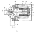
- the wet rotor pump has a pump wheel 10, through the rotation of which medium in the direction of an arrow 12 through an intake duct 14 and in Direction of an arrow 16 is conveyed through a delivery channel 18.
- the Intake duct 14 and discharge duct 18 are part of a pump cover 20, in which the pump wheel 10 is arranged.
- the impeller 10 has a shaft 22 firmly connected.
- a motor rotor 24 Motor 26 firmly connected.
- the motor rotor 24 is of a winding 28 having stand package 30 surrounded.
- the stand package 30 is opposite the motor rotor or rotor 24 axially offset to the left in FIG. 1, so that the magnetic axial pull acts in the same direction as the hydraulic axial pull.
- the pump 26 is used to cool the motor 26 Medium.
- the medium passes behind the pump wheel in the conveying direction 12 10 in a rotor chamber 32.
- electronic components come into contact with the medium.
- the Motor rotor 24 surrounded with a containment shell 34. Through the can 34 is a narrow gap between the motor rotor 24 and an inside of the containment shell 34 trained.
- the can 34 is connected to a housing half 36 and sealed against this.
- the containment shell 34 and the housing half 36 can also form a unit.
- a second housing half 38 is with the first Housing half 36 connected and encloses the motor 26.
- the shaft 22 is supported in a first radial bearing 40, which is a the containment shell 34 has bearing sleeve 42 held.
- the opposite Shaft end to which the pump wheel 10 is attached is according to the invention in a support element 44 is mounted.
- the support element has a Opening 46 on.
- the opening 46 is cylindrical and coaxial with the shaft 22.
- a bearing sleeve 48 through which a plain bearing in the Support element 44 is formed.
- the axial bearing of the shaft 22 is carried out according to the invention by the Support element provided, extending essentially radially to the shaft 22 Approach surface.
- the contact surface is an opening 46 surrounding annulus.
- Axial forces into the other Direction i.e. to the right in the figure, do not occur. Even those through the Axial forces caused by motor 26 point to the left or are in the figure less than the forces caused by the pressure difference.
- the inflow surface 52 is preferably convex (FIG. 2), but can through geometric elements such as Grooves or similar (Fig. 3,4) that an improved Wetting the contact surface between the contact surface 50 and the inflow surface 52 serve, be supplemented and touches a flat, radially extending contact surface 50. Possibly. the contact surface 50 is concave, so that in addition a radial Alignment of the pump wheel 10 takes place.
- the design of the inflow surface 52 and contact surface 54 can also be reversed.
- the support element 44 is connected to the intake pipe 14 via webs 54. Preferably on the circumference of the shaft 22 to the central axis rotationally symmetrical support element three webs 54 are provided.
- the outer contour of the support element 44 is preferably streamlined, so that the medium flowing in the direction of arrow 12 from the support element the impeller 10 is steered.
- the inflow side of the Support element in cross-section partially elliptical.
- the rotor 24 and the pump wheel 10 are first placed on the shaft 22 attached. Grooves or the like can be used for fixation. be provided. The impeller 10 is pushed onto the shaft 22 until it abuts a shoulder 58. The shaft end 60 of the shaft 22 is then inserted into the support element 44 arranged bearing sleeve 48 inserted. After inserting the shaft 22 in the sleeve 48 is the inflow surface 52 of the impeller 10 on the thrust surface 50 of the support element 44.
- By mounting the shaft 22 in the area of Pump wheel 10 is a very precise positioning of the pump wheel 10 in the Pump cover 20 possible. This ensures a minimal leakage gap.
Landscapes
- Engineering & Computer Science (AREA)
- Mechanical Engineering (AREA)
- General Engineering & Computer Science (AREA)
- Physics & Mathematics (AREA)
- Fluid Mechanics (AREA)
- Structures Of Non-Positive Displacement Pumps (AREA)
Abstract
Description
- Fig. 1
- eine prinzipielle schematische Querschnittsansicht einer erfindungsgemäßen Naßläuferpumpe, und
- Fign.2-4
- bevorzugte Ausführungsformen einer Anströmfläche.
Claims (6)
- Naßläuferpumpe, insbesondere zur Kühlmittelförderung in Kraftfahrzeug-Motoren, mit
einem in Förderrichtung (12) einem Ansaugkanal (14) nachgeschalteten Pumpenrad (10),
einem über eine gemeinsame Welle (22) mit dem Pumpenrad (10) verbundenen Motorläufer (24),
einem den Motorläufer (24) umgebenden Spalttopf (34), wobei der Motorläufer (24) zur Kühlung von Fördermedium umspült wird, und
mindestens einem Radiallager (40,48),
gekennzeichnet durch
ein im Ansaugkanal (14) vorgesehenes Abstützelement (44) mit einer Anlauffläche (50), gegen die eine Anströmfläche (52) des Pumpenrades (10) zur Aufnahme von Axialkräften anläuft. - Naßläuferpumpe nach Anspruch 1, dadurch gekennzeichnet, dass die Anlauffläche (50) und/oder die Anströmfläche (52) radial zur Welle (22) verlaufen.
- Naßläuferpumpe nach Anspruch 1 oder 2, dadurch gekennzeichnet, dass die Anlauffläche (50) oder die Anströmfläche (52) konvex ist.
- Naßläuferpumpe nach einem der Ansprüche 1-3, dadurch gekennzeichnet, dass die Anlauffläche (54) oder vorzugsweise die Anströmfläche (52) durch Geometrieelemente, die einer Verbesserung der Schmierung der Kontaktfläche dienen, ergänzt sind.
- Naßläuferpumpe nach einem der Ansprüche 1-4, dadurch gekennzeichnet, dass das Abstützelement (44) ein Radiallager (48) der Welle (22) trägt.
- Naßläuferpumpe nach einem der Ansprüche 1-5, dadurch gekennzeichnet, dass das Abstützelement (44) über Stege (54) mit dem Ansaugkanal (14) verbunden ist.
Applications Claiming Priority (2)
| Application Number | Priority Date | Filing Date | Title |
|---|---|---|---|
| DE10140613 | 2001-08-18 | ||
| DE10140613A DE10140613A1 (de) | 2001-08-18 | 2001-08-18 | Naßläuferpumpe |
Publications (2)
| Publication Number | Publication Date |
|---|---|
| EP1286055A1 true EP1286055A1 (de) | 2003-02-26 |
| EP1286055B1 EP1286055B1 (de) | 2006-02-08 |
Family
ID=7695908
Family Applications (1)
| Application Number | Title | Priority Date | Filing Date |
|---|---|---|---|
| EP02017197A Expired - Lifetime EP1286055B1 (de) | 2001-08-18 | 2002-07-31 | Nassläuferpumpe |
Country Status (4)
| Country | Link |
|---|---|
| US (1) | US6939115B2 (de) |
| EP (1) | EP1286055B1 (de) |
| DE (2) | DE10140613A1 (de) |
| ES (1) | ES2253479T3 (de) |
Cited By (1)
| Publication number | Priority date | Publication date | Assignee | Title |
|---|---|---|---|---|
| DE10352487A1 (de) * | 2003-07-22 | 2005-02-10 | BSH Bosch und Siemens Hausgeräte GmbH | Pumpe mit integriertem Motor |
Families Citing this family (17)
| Publication number | Priority date | Publication date | Assignee | Title |
|---|---|---|---|---|
| GB2399863B (en) * | 2003-03-28 | 2007-01-03 | Alfred William Crook | Gas compressor |
| EP1719916B1 (de) * | 2005-05-07 | 2008-07-23 | Grundfos Management A/S | Pumpenaggregat |
| JP4293207B2 (ja) * | 2006-07-21 | 2009-07-08 | 株式会社日立製作所 | 電動ポンプ |
| DE102007010050A1 (de) * | 2007-03-01 | 2008-09-04 | Continental Automotive Gmbh | Kreiselpumpe mit einem Spiralgehäuse |
| DE102007010051A1 (de) * | 2007-03-01 | 2008-09-04 | Continental Automotive Gmbh | Kreiselpumpe mit einem Spiralgehäuse |
| JP5529714B2 (ja) * | 2010-11-12 | 2014-06-25 | 三菱重工業株式会社 | 電動過給機の回転軸支持構造 |
| DE102011075227A1 (de) * | 2011-05-04 | 2012-11-08 | BSH Bosch und Siemens Hausgeräte GmbH | Axiallager für einen elektrischen Antrieb |
| US9360015B2 (en) | 2012-07-16 | 2016-06-07 | Magna Powertrain Of America, Inc. | Submerged rotor electric water pump with structural wetsleeve |
| DE102012216196A1 (de) * | 2012-09-12 | 2014-03-13 | E.G.O. Elektro-Gerätebau GmbH | Pumpe |
| DE102013014139A1 (de) * | 2012-12-21 | 2014-06-26 | Brose Fahrzeugteile GmbH & Co. Kommanditgesellschaft, Würzburg | Elektromotorische Wasserpumpe |
| JP2014145269A (ja) * | 2013-01-28 | 2014-08-14 | Asmo Co Ltd | 車両用ポンプ装置 |
| AU2014352977A1 (en) | 2013-11-20 | 2016-06-09 | Endostim, Inc. | Systems and methods for electrical stimulation of biological systems |
| DE102016202417A1 (de) * | 2016-02-17 | 2017-08-17 | Bühler Motor GmbH | Kreiselpumpe |
| KR102130283B1 (ko) | 2018-07-27 | 2020-08-05 | 주식회사 코아비스 | 임펠러 지지구조를 포함하는 워터 펌프 |
| KR102365863B1 (ko) * | 2021-06-09 | 2022-02-23 | 주식회사 코아비스 | 워터 펌프 |
| DE102021207404A1 (de) | 2021-07-13 | 2023-01-19 | Robert Bosch Gesellschaft mit beschränkter Haftung | Pumpenvorrichtung, insbesondere Magnetkupplungspumpenvorrichtung |
| DE102023205260A1 (de) | 2023-06-06 | 2024-12-12 | Robert Bosch Gesellschaft mit beschränkter Haftung | Fluidpumpe, insbesondere Kühlmittelpumpe |
Citations (6)
| Publication number | Priority date | Publication date | Assignee | Title |
|---|---|---|---|---|
| FR1157493A (fr) * | 1956-08-28 | 1958-05-29 | Emerjy | Perfectionnements aux groupes électro-pompes pour chauffage central et analogues |
| FR1272780A (fr) * | 1960-11-02 | 1961-09-29 | Hollesens Fabrikker H | Perfectionnements apportés aux pompes à liquides entraînées par moteurs électriques |
| FR1414030A (fr) * | 1964-09-04 | 1965-10-15 | Rech S Et D Expl S Ind Soc D | Perfectionnements aux motopompes |
| US3433164A (en) * | 1967-03-03 | 1969-03-18 | Buffalo Forge Co | Motor-pump unit |
| DE1811430A1 (de) * | 1968-11-25 | 1970-06-11 | Gummi Jaeger Kg Gmbh & Cie | Hydraulische Stroemungsmaschine |
| US3853429A (en) * | 1972-09-14 | 1974-12-10 | Eheim G | Motor pump combination |
Family Cites Families (17)
| Publication number | Priority date | Publication date | Assignee | Title |
|---|---|---|---|---|
| US2799227A (en) * | 1954-07-21 | 1957-07-16 | Westinghouse Electric Corp | Thrust bearing |
| US3060861A (en) * | 1959-06-15 | 1962-10-30 | Klein Schanzlin & Becker Ag | Rotary pumps without shaft packing |
| NL261455A (de) * | 1960-02-23 | |||
| US3090655A (en) * | 1960-10-14 | 1963-05-21 | Gen Motors Corp | Thrust bearing |
| US3186513A (en) * | 1962-11-09 | 1965-06-01 | James T E Dunn | Method and mechanism for lubricating the bearings of a pump rotor and motor combination for pumping an abradant-containing liquid |
| DE2338395C3 (de) * | 1973-07-28 | 1984-04-05 | SWF-Spezialfabrik für Autozubehör Gustav Rau GmbH, 7120 Bietigheim-Bissingen | Kraftstoffförderpumpe, insbesondere für Kraftfahrzeuge |
| JPS5735196A (en) * | 1980-08-09 | 1982-02-25 | Sansou Denki Kk | Motor-driven pump |
| JPS5773892A (en) * | 1980-10-27 | 1982-05-08 | Teikoku Denki Seisakusho:Kk | Operation monitor for magnetic coupling pump |
| JPS60234120A (ja) * | 1984-05-07 | 1985-11-20 | Canon Inc | 動圧スラスト軸受 |
| JPH0647991B2 (ja) * | 1986-05-15 | 1994-06-22 | 三菱電機株式会社 | スクロ−ル圧縮機 |
| FR2649450A1 (fr) * | 1989-07-07 | 1991-01-11 | Rena Sa | Pompe rotative a entrainement electrique |
| US5599112A (en) * | 1995-08-17 | 1997-02-04 | Ansimag Inc. | Axial bearing having a variable coefficient of friction for monitoring wear |
| DE19545561A1 (de) | 1995-12-07 | 1997-06-12 | Pierburg Ag | Pumpe-Motoreinheit |
| GB2307947B (en) * | 1995-12-08 | 1999-08-18 | Aisan Ind | Magnetically coupled pump |
| DE19618767A1 (de) * | 1996-05-10 | 1997-11-13 | Wilo Gmbh | Selbsteinstellendes Axiallager für Hochdruckkreiselpumpen |
| DE19956380C1 (de) * | 1999-11-24 | 2001-01-04 | Bosch Gmbh Robert | Flüssigkeitspumpe mit einem Motorgehäuse und Verfahren zur Herstellung eines Motorgehäuses |
| US6309188B1 (en) * | 2000-06-07 | 2001-10-30 | Michael Danner | Magnetic drive centrifugal pump having ceramic bearings, ceramic thrust washers, and a water cooling channel |
-
2001
- 2001-08-18 DE DE10140613A patent/DE10140613A1/de not_active Withdrawn
-
2002
- 2002-07-31 EP EP02017197A patent/EP1286055B1/de not_active Expired - Lifetime
- 2002-07-31 DE DE50205779T patent/DE50205779D1/de not_active Expired - Lifetime
- 2002-07-31 ES ES02017197T patent/ES2253479T3/es not_active Expired - Lifetime
- 2002-08-02 US US10/211,963 patent/US6939115B2/en not_active Expired - Fee Related
Patent Citations (6)
| Publication number | Priority date | Publication date | Assignee | Title |
|---|---|---|---|---|
| FR1157493A (fr) * | 1956-08-28 | 1958-05-29 | Emerjy | Perfectionnements aux groupes électro-pompes pour chauffage central et analogues |
| FR1272780A (fr) * | 1960-11-02 | 1961-09-29 | Hollesens Fabrikker H | Perfectionnements apportés aux pompes à liquides entraînées par moteurs électriques |
| FR1414030A (fr) * | 1964-09-04 | 1965-10-15 | Rech S Et D Expl S Ind Soc D | Perfectionnements aux motopompes |
| US3433164A (en) * | 1967-03-03 | 1969-03-18 | Buffalo Forge Co | Motor-pump unit |
| DE1811430A1 (de) * | 1968-11-25 | 1970-06-11 | Gummi Jaeger Kg Gmbh & Cie | Hydraulische Stroemungsmaschine |
| US3853429A (en) * | 1972-09-14 | 1974-12-10 | Eheim G | Motor pump combination |
Cited By (1)
| Publication number | Priority date | Publication date | Assignee | Title |
|---|---|---|---|---|
| DE10352487A1 (de) * | 2003-07-22 | 2005-02-10 | BSH Bosch und Siemens Hausgeräte GmbH | Pumpe mit integriertem Motor |
Also Published As
| Publication number | Publication date |
|---|---|
| EP1286055B1 (de) | 2006-02-08 |
| US6939115B2 (en) | 2005-09-06 |
| ES2253479T3 (es) | 2006-06-01 |
| DE10140613A1 (de) | 2003-03-06 |
| US20030035740A1 (en) | 2003-02-20 |
| DE50205779D1 (de) | 2006-04-20 |
Similar Documents
| Publication | Publication Date | Title |
|---|---|---|
| EP1286055B1 (de) | Nassläuferpumpe | |
| EP1309070A2 (de) | Nassläuferpumpe mit Schutzeinrichtung gegen Korrosion | |
| DE2750801C2 (de) | Pumpe, insbesondere Faßpumpe | |
| WO2009037019A1 (de) | Pumpenrotor für eine spaltrohrpumpe | |
| DE102013017975A1 (de) | Elektromotorisch angetriebene Flüssigkeitspumpe, insbesondere zur Zwangsschmierung eines Schaltgetriebes für Kraftfahrzeuge | |
| DE102018125031A1 (de) | Pumpe, insbesondere für einen Flüssigkeitskreislauf in einem Fahrzeug | |
| EP1191232A2 (de) | Elektrisch angetriebene Kühlmittelpumpe | |
| EP2072826A1 (de) | Rotor für einem Spaltrohrmotor | |
| DE102016105309A1 (de) | Magnetkupplungspumpe | |
| WO2020074318A1 (de) | Pumpe, insbesondere für einen flüssigkeitskreislauf in einem fahrzeug | |
| DE2262569A1 (de) | Foerderaggregat fuer fluessigkeiten | |
| WO2007033818A1 (de) | Spaltrohr | |
| DE69527605T2 (de) | Lageranordnung zur Verwendung in einer Pumpe | |
| DE19939522A1 (de) | Elektromotorisch angetriebene Kreiselpumpe mit außenliegendem Rotor | |
| EP2721301A1 (de) | Tauchpumpe und verfahren zum zusammenbau einer tauchpumpe | |
| DE102021133692A1 (de) | Elektrische Kraftfahrzeug-Fluidpumpe | |
| WO2010100021A2 (de) | Flügelzellenpumpe | |
| DE29716110U1 (de) | Magnetkupplungspumpe | |
| DE10301613B4 (de) | Motor-Pumpeneinheit | |
| EP1945955B1 (de) | Fluidpumpe | |
| DE202004013080U1 (de) | Magnetkupplungspumpe | |
| DE102021133447A1 (de) | Magnetkupplungspumpenanordnung | |
| DE102021212381A1 (de) | Pumpe und Kraftfahrzeug mit mindestens einer derartigen Pumpe | |
| DE102019115774A1 (de) | Pumpe, insbesondere Pumpe für einen Flüssigkeitskreislauf in einem Fahrzeug, mit einem Kranz eines Laufrades, eintauchend in ein Gehäuse | |
| DE102020118009A1 (de) | Schraubenspindelpumpe zur Förderung eines Fluids |
Legal Events
| Date | Code | Title | Description |
|---|---|---|---|
| PUAI | Public reference made under article 153(3) epc to a published international application that has entered the european phase |
Free format text: ORIGINAL CODE: 0009012 |
|
| AK | Designated contracting states |
Kind code of ref document: A1 Designated state(s): AT BE BG CH CY CZ DE DK EE ES FI FR GB GR IE IT LI LU MC NL PT SE SK TR |
|
| AX | Request for extension of the european patent |
Extension state: AL LT LV MK RO SI |
|
| 17P | Request for examination filed |
Effective date: 20030408 |
|
| AKX | Designation fees paid |
Designated state(s): DE ES FR GB IT |
|
| 17Q | First examination report despatched |
Effective date: 20041123 |
|
| GRAP | Despatch of communication of intention to grant a patent |
Free format text: ORIGINAL CODE: EPIDOSNIGR1 |
|
| GRAS | Grant fee paid |
Free format text: ORIGINAL CODE: EPIDOSNIGR3 |
|
| GRAA | (expected) grant |
Free format text: ORIGINAL CODE: 0009210 |
|
| AK | Designated contracting states |
Kind code of ref document: B1 Designated state(s): DE ES FR GB IT |
|
| REG | Reference to a national code |
Ref country code: GB Ref legal event code: FG4D Free format text: NOT ENGLISH |
|
| GBT | Gb: translation of ep patent filed (gb section 77(6)(a)/1977) |
Effective date: 20060309 |
|
| REF | Corresponds to: |
Ref document number: 50205779 Country of ref document: DE Date of ref document: 20060420 Kind code of ref document: P |
|
| REG | Reference to a national code |
Ref country code: ES Ref legal event code: FG2A Ref document number: 2253479 Country of ref document: ES Kind code of ref document: T3 |
|
| PGFP | Annual fee paid to national office [announced via postgrant information from national office to epo] |
Ref country code: FR Payment date: 20060714 Year of fee payment: 5 |
|
| PGFP | Annual fee paid to national office [announced via postgrant information from national office to epo] |
Ref country code: GB Payment date: 20060720 Year of fee payment: 5 |
|
| PGFP | Annual fee paid to national office [announced via postgrant information from national office to epo] |
Ref country code: IT Payment date: 20060731 Year of fee payment: 5 |
|
| ET | Fr: translation filed | ||
| PLBE | No opposition filed within time limit |
Free format text: ORIGINAL CODE: 0009261 |
|
| STAA | Information on the status of an ep patent application or granted ep patent |
Free format text: STATUS: NO OPPOSITION FILED WITHIN TIME LIMIT |
|
| 26N | No opposition filed |
Effective date: 20061109 |
|
| GBPC | Gb: european patent ceased through non-payment of renewal fee |
Effective date: 20070731 |
|
| PG25 | Lapsed in a contracting state [announced via postgrant information from national office to epo] |
Ref country code: GB Free format text: LAPSE BECAUSE OF NON-PAYMENT OF DUE FEES Effective date: 20070731 |
|
| REG | Reference to a national code |
Ref country code: FR Ref legal event code: ST Effective date: 20080331 |
|
| PG25 | Lapsed in a contracting state [announced via postgrant information from national office to epo] |
Ref country code: FR Free format text: LAPSE BECAUSE OF NON-PAYMENT OF DUE FEES Effective date: 20070731 |
|
| REG | Reference to a national code |
Ref country code: ES Ref legal event code: FD2A Effective date: 20070801 |
|
| PG25 | Lapsed in a contracting state [announced via postgrant information from national office to epo] |
Ref country code: ES Free format text: LAPSE BECAUSE OF NON-PAYMENT OF DUE FEES Effective date: 20070801 |
|
| PG25 | Lapsed in a contracting state [announced via postgrant information from national office to epo] |
Ref country code: IT Free format text: LAPSE BECAUSE OF NON-PAYMENT OF DUE FEES Effective date: 20070731 |
|
| PGFP | Annual fee paid to national office [announced via postgrant information from national office to epo] |
Ref country code: DE Payment date: 20160721 Year of fee payment: 15 |
|
| REG | Reference to a national code |
Ref country code: DE Ref legal event code: R119 Ref document number: 50205779 Country of ref document: DE |
|
| PG25 | Lapsed in a contracting state [announced via postgrant information from national office to epo] |
Ref country code: DE Free format text: LAPSE BECAUSE OF NON-PAYMENT OF DUE FEES Effective date: 20180201 |