EP1286059A2 - Système de séparation des canaux pour fluide sous pression et élément structurel du canal - Google Patents
Système de séparation des canaux pour fluide sous pression et élément structurel du canal Download PDFInfo
- Publication number
- EP1286059A2 EP1286059A2 EP20020018451 EP02018451A EP1286059A2 EP 1286059 A2 EP1286059 A2 EP 1286059A2 EP 20020018451 EP20020018451 EP 20020018451 EP 02018451 A EP02018451 A EP 02018451A EP 1286059 A2 EP1286059 A2 EP 1286059A2
- Authority
- EP
- European Patent Office
- Prior art keywords
- channel
- pressure medium
- subdivision
- locking
- duct
- Prior art date
- Legal status (The legal status is an assumption and is not a legal conclusion. Google has not performed a legal analysis and makes no representation as to the accuracy of the status listed.)
- Granted
Links
- 239000012530 fluid Substances 0.000 title claims description 10
- 238000007789 sealing Methods 0.000 claims abstract description 36
- 230000003993 interaction Effects 0.000 claims description 3
- 238000000638 solvent extraction Methods 0.000 claims description 2
- 238000005192 partition Methods 0.000 description 7
- 239000000565 sealant Substances 0.000 description 7
- 230000000694 effects Effects 0.000 description 4
- 238000000034 method Methods 0.000 description 4
- 230000008569 process Effects 0.000 description 4
- 238000003780 insertion Methods 0.000 description 2
- 230000037431 insertion Effects 0.000 description 2
- 238000004519 manufacturing process Methods 0.000 description 2
- 239000000463 material Substances 0.000 description 2
- 229910052751 metal Inorganic materials 0.000 description 2
- 239000002184 metal Substances 0.000 description 2
- 229910052782 aluminium Inorganic materials 0.000 description 1
- XAGFODPZIPBFFR-UHFFFAOYSA-N aluminium Chemical compound [Al] XAGFODPZIPBFFR-UHFFFAOYSA-N 0.000 description 1
- 230000004888 barrier function Effects 0.000 description 1
- 230000008901 benefit Effects 0.000 description 1
- 230000005540 biological transmission Effects 0.000 description 1
- 230000000295 complement effect Effects 0.000 description 1
- 239000002131 composite material Substances 0.000 description 1
- 238000010276 construction Methods 0.000 description 1
- 238000011161 development Methods 0.000 description 1
- 230000018109 developmental process Effects 0.000 description 1
- 230000004069 differentiation Effects 0.000 description 1
- 239000000834 fixative Substances 0.000 description 1
- 230000012447 hatching Effects 0.000 description 1
- 238000001746 injection moulding Methods 0.000 description 1
- 230000010354 integration Effects 0.000 description 1
- 230000013011 mating Effects 0.000 description 1
- 230000002093 peripheral effect Effects 0.000 description 1
- 238000009420 retrofitting Methods 0.000 description 1
Images
Classifications
-
- F—MECHANICAL ENGINEERING; LIGHTING; HEATING; WEAPONS; BLASTING
- F15—FLUID-PRESSURE ACTUATORS; HYDRAULICS OR PNEUMATICS IN GENERAL
- F15B—SYSTEMS ACTING BY MEANS OF FLUIDS IN GENERAL; FLUID-PRESSURE ACTUATORS, e.g. SERVOMOTORS; DETAILS OF FLUID-PRESSURE SYSTEMS, NOT OTHERWISE PROVIDED FOR
- F15B13/00—Details of servomotor systems ; Valves for servomotor systems
- F15B13/02—Fluid distribution or supply devices characterised by their adaptation to the control of servomotors
- F15B13/06—Fluid distribution or supply devices characterised by their adaptation to the control of servomotors for use with two or more servomotors
- F15B13/08—Assemblies of units, each for the control of a single servomotor only
- F15B13/0803—Modular units
- F15B13/0807—Manifolds
- F15B13/0814—Monoblock manifolds
-
- F—MECHANICAL ENGINEERING; LIGHTING; HEATING; WEAPONS; BLASTING
- F15—FLUID-PRESSURE ACTUATORS; HYDRAULICS OR PNEUMATICS IN GENERAL
- F15B—SYSTEMS ACTING BY MEANS OF FLUIDS IN GENERAL; FLUID-PRESSURE ACTUATORS, e.g. SERVOMOTORS; DETAILS OF FLUID-PRESSURE SYSTEMS, NOT OTHERWISE PROVIDED FOR
- F15B13/00—Details of servomotor systems ; Valves for servomotor systems
- F15B13/02—Fluid distribution or supply devices characterised by their adaptation to the control of servomotors
- F15B13/06—Fluid distribution or supply devices characterised by their adaptation to the control of servomotors for use with two or more servomotors
- F15B13/08—Assemblies of units, each for the control of a single servomotor only
- F15B13/0803—Modular units
- F15B13/0878—Assembly of modular units
- F15B13/0885—Assembly of modular units using valves combined with other components
- F15B13/0892—Valves combined with fluid components
-
- F—MECHANICAL ENGINEERING; LIGHTING; HEATING; WEAPONS; BLASTING
- F16—ENGINEERING ELEMENTS AND UNITS; GENERAL MEASURES FOR PRODUCING AND MAINTAINING EFFECTIVE FUNCTIONING OF MACHINES OR INSTALLATIONS; THERMAL INSULATION IN GENERAL
- F16L—PIPES; JOINTS OR FITTINGS FOR PIPES; SUPPORTS FOR PIPES, CABLES OR PROTECTIVE TUBING; MEANS FOR THERMAL INSULATION IN GENERAL
- F16L41/00—Branching pipes; Joining pipes to walls
- F16L41/02—Branch units, e.g. made in one piece, welded, riveted
- F16L41/03—Branch units, e.g. made in one piece, welded, riveted comprising junction pieces for four or more pipe members
-
- Y—GENERAL TAGGING OF NEW TECHNOLOGICAL DEVELOPMENTS; GENERAL TAGGING OF CROSS-SECTIONAL TECHNOLOGIES SPANNING OVER SEVERAL SECTIONS OF THE IPC; TECHNICAL SUBJECTS COVERED BY FORMER USPC CROSS-REFERENCE ART COLLECTIONS [XRACs] AND DIGESTS
- Y10—TECHNICAL SUBJECTS COVERED BY FORMER USPC
- Y10T—TECHNICAL SUBJECTS COVERED BY FORMER US CLASSIFICATION
- Y10T137/00—Fluid handling
- Y10T137/5109—Convertible
Definitions
- the invention relates to a subdivision device for fluid-tight Subdivision of one provided in a duct component Pressure medium channel in two successive channel sections, with one to the desired subdivision point duct dividers that can be inserted into the respective pressure medium duct, the with for sealing interaction with the Sealing means provided in the channel wall of the pressure medium channel is equipped, and with fixing means for fixing the Channel divider at the subdivision point.
- the invention relates to a channel component that at least has a pressure medium channel and with a subdivision device of the type mentioned above.
- DE 197 04 006 C2 describes a valve carrier Duct component that consists of several pressure medium ducts is crossed, from which branch channels branch off to one Open the placement area. Can on the assembly area Valves are mounted, which are via the pressure medium channels of the Duct component are supplied with pressure medium.
- One of Pressure medium channels is by means of a subdivision device divided into two successive channel sections in a fluid-tight manner, so that different pressure zones can be realized can.
- the dividing device includes one of several Single element composite duct divider, the to the desired subdivision point in the relevant Pressure medium channel can be inserted. There he leaves by operating an integrated clamping device with the Tension the duct wall and fix it in place. simultaneously an annular seal on the channel wall during the clamping process pressed.
- It is the object of the present invention to provide a dividing device of the type mentioned at the outset to create the has a simple structure, light and reliable Sealing can be installed and also with very small dimensions can be realized. Furthermore, a Channel component are created with at least one subdivision device is equipped to meet these conditions Fulfills.
- the channel divider as a plug in the pressure medium channel in question placeable fitting with in the area of the outer circumference arranged sealing means is formed and that the Fixing means are designed as locking means and at least one through one opening into the pressure medium channel Cross channel through with the channel divider in locking engagement bringable locking part included.
- the object is further achieved by a channel component that has at least one pressure medium channel and with at least a subdivision device dividing the pressure medium channel in a fluid-tight manner equipped according to the aforementioned specification is.
- the dividing device according to the invention can be like a Plug by pushing it into the assigned pressure medium channel be placed at the desired subdivision location, whereby that matched to the cross section of the pressure medium channel Fit in connection with the circumferentially arranged Sealants easily a reliable fluid tight Subdivision guaranteed and especially on integration a special clamping device in the duct divider can be dispensed with.
- the desired sealing contact is solely through the shape of the duct divider as a fitting already guaranteed.
- the fixed fixation is based on a locking effect, with a locking part in a transverse channel connected to the pressure medium channel is inserted until it protrudes into the pressure medium channel and interlocks with the channel divider.
- the locking means expediently contain at least one provided on the outer circumference of the duct divider Locking recess into which the locking part engages can. This locking recess is useful than over the entire outer circumference of the duct divider extending groove formed so that the channel divider when inserting it into the duct component, no special one Alignment is required.
- Locking part and channel divider are preferably like this 'matched to each other that there is a positive locking engagement results in the channel divider axially immobile or at best stationary with little play is held.
- channel divider in particular integrally formed subdivision body and sealing means arranged thereon.
- the subdivision body can be made of both metal and plastic material be made.
- the sealant can be an integral part of the Channel divider, for example by passing through Injection molding are molded onto the subdivision body. at a further embodiment has the sealing means via one held in a circumferential groove of the partition body Sealing ring.
- the channel divider expediently has in the area of Sealant over a fit section that is formed is that he assigned the entire cross section of the Fills the pressure medium channel and that actually for the fluid-tight subdivision responsible component of the duct divider represents.
- the channel divider but have another fit section, whose cross section only the assigned pressure medium channel partially filled so that the pressure medium can flow past if necessary can.
- the point of attack for the locking part in this case is preferably axially between the two Fit sections arranged.
- the locking part is preferably designed like a pin. It also has its when it takes the locking position the outer end opposite the duct divider expediently via a handling section on which the Locking part when inserting into the cross channel or when Pulling out of this can be easily captured.
- the locking part can be secured by suitable securing means in locking engagement with the duct divider Locking position can be fixed.
- suitable securing means in locking engagement with the duct divider Locking position can be fixed.
- the securing part can be designed like a lid be and have sealants at the channel component attached condition of the securing part around the mouth the cross channel around with the channel component in sealing contact stand. In this way, pressure medium escapes prevented from the pressure medium channel through the cross channel, if the channel divider is designed so that it the access of the pressure medium inside the pressure medium channel not prevented in the junction area of the cross channel.
- the subdivision device is particularly suitable for one Use in connection with a duct component that acts as a valve carrier is designed and used for fluid control Valves is or can be equipped.
- a duct component that acts as a valve carrier is designed and used for fluid control Valves is or can be equipped.
- Has one such duct component over from the inside Pressure medium channel outgoing branch channels leading to an assembly area lead for the valves there is the advantageous Possibility to use at least one of these branch channels as a cross channel be used to hold the locking part.
- a transverse channel provided for receiving the locking part, This has the advantage that existing duct components without any design changes with the subdivision device can be equipped.
- the point of attack for the locking part on the mutual Distance between the opening into the pressure medium channel Branch channels are tuned to be the point of attack for that Locking part at the same level with a branch channel if the duct divider is in contact with a stop part is inserted into the pressure medium channel, the through an adjacent branch channel into the pressure medium channel protrudes. In this way, the point of attack very easy and precise in the area of the as a cross channel for recording of the locking part to be used branch channel positioned become.
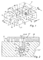
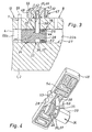
- FIG. 1 A duct component interspersed with ducts emerges from the drawing 1, wherein in Fig. 1 a longitudinal section of this channel component 1 is shown and Figures 2 and 3 simplified Show sectional views of the channel component 1, at some of the channels are not shown for the sake of simplicity are.
- the channel component 1 has in particular plate or strip-shaped Shape and forms a valve carrier in the embodiment 2, with a plurality of for fluid control serving valves 3 can be equipped. 1 is one of these valves 3 indicated by dash-dotted lines.
- the channel component 1 has a function as a feed channel Pressure medium channel, which for better differentiation in The following is referred to as the first pressure medium channel 4. He passes through the channel component 1 in its longitudinal direction.
- Pressure medium channels 5 also run within the Channel component 1 and extend parallel to the first Pressure medium channel 4. They are preferably Discharge channels. In Figures 2 and 3 is only the first Pressure medium channel 4 can be seen.
- Fluidic pressure medium can flow through the first pressure medium channel 4 be fed, for example a hydraulic Pressure medium, but preferably compressed air. About the others Pressure medium channels 5 can do this via the first pressure medium channel 4 fed pressure medium at least partially discharged again become.
- first pressure medium channel 4 From the first pressure medium channel 4 go in the longitudinal direction at a distance from each other branch points 6 one or more branch channels 7 from - in the embodiment each two pieces - which are transverse and preferably rectangular run to the longitudinal extent of the first pressure medium channel 4 and on the outside of the channel component 1 on a common assembly surface 8 open out.
- valves 3 are mounted, in particular so-called multi-way valves. As already mentioned, is in the Drawing of only one of these valves 3 in dash-dotted lines Shape shown. In fully stocked condition sits on the channel member 1, a plurality of valves 3, the in the longitudinal direction of the channel component 1 successively are arranged.
- Branch channels 13 open in a comparable manner to the individual Assembly places 12 to the assembly area 8.
- the channel component 1 also contains working channels 14, that proceed from the placement surfaces 12 to another lead longitudinal outer surface of the channel member 1, where they end with connection openings 15.
- the connection openings 15 are designed so that fluid lines connect to them let that operate to one or more Lead consumers, for example to fluid-operated drives.
- the valves 3 are in a manner known per se with one or equipped with several valve members in one or more Valve chambers are arranged with valve channels communicate. These valve channels open out to a mounting surface of the respective valve 3 with which the relevant Valve 3 at the assigned placement location 12 of the placement area 8 is mountable.
- the mouths of the valve channels are aligned so that they match those at the assembly stations 12 located mouths of the branch channels 7, 13 and working channels 14 are aligned and thereby a fluid There is a connection.
- the channel component 1 acts as it were as a fluid distributor.
- the feeding of the pressure medium into the first pressure medium channel 4 expediently takes place on the end face of the channel component 1. Is the same for all connected valves 3 If supply pressure is provided, the pressure medium is fed in expediently from only one end face of the channel component 1 ago, for example via the in Fig. 1st visible channel end 17 provided an end face 16 of the first pressure medium channel 4.
- the on the opposite, other end face, not shown, of the channel component 1 lying channel mouth of the first pressure medium channel 4 can in be closed in this case, for example by a suitable one Sealing unit.
- the subdivision device 18 fluid-tight subdivision of the first pressure medium channel 4 in two successively arranged first and second channel sections 22a, 22b.
- the dividing device 18 acts within of the first pressure medium channel 4 as a partition, wherein there is now the possibility of the two channel sections 22a, 22b independently of one another and in particular with one another to supply different pressure level with pressure medium, the then over that of the relevant channel section 22a, 22b outgoing branch channels 7 to the connected valves 3 Available. While the first channel section 22a continues fed via the channel mouth 17 on one end face 16 is then conveniently the supply of the other, second channel section 22b over the at the opposite End face of the channel component 1 provided channel mouth time.
- Subdivision point 23 denotes.
- One possible position is marked by hatching in FIG. 1.
- the partitioning device 18 includes one by one of the End openings of the first pressure medium duct 4 through into this first pressure medium channel 4 insertable channel divider 24 with a simple rod or one other suitable object to the desired subdivision point 23 can be inserted.
- the channel divider 24 can be very simple and consists in the embodiment of only one piece Subdivision body 25 with in the region of the radially oriented Sealing means 26 arranged on the outer circumference.
- the sealing means 26 are for sealing interaction provided with the channel wall 27 of the first pressure medium channel 4.
- In connection with the gas impermeable Subdivision body 25 can thus through the channel divider 24 effective within the first pressure medium channel 4 Barrier for what is fed into the first pressure medium channel 4 Pressure means are created.
- the channel divider 24 does not contain any means that follow to be pushed into the first pressure medium channel 4 would be to the required sealing contact between the sealants 26 and the channel wall 27. root cause this is the design of the channel divider chosen from the outset as a fitting, whose outer contour is already on the inner contour of the first pressure medium channel 4 is adapted in this way is that the desired sealing effect is given.
- the channel divider 24 needs comparable to a graft be placed at the desired subdivision location 23, where the sealing means 26 immediately the desired sealing effect unfold.
- the sealing means 26 will be designed in such a way that their outline before insertion into the first pressure medium channel 4 is slightly larger than that of the first Pressure medium channel 4, so that when inserting the channel divider 24 are radially elastically deformed and a Restoring force with which the sealing means 26 against the channel wall 27 are biased.
- the outer contour of the partition body 25 is also on adapted the inner contour of the first pressure medium channel 4, wherein the fit is chosen so that the subdivision body 25, considered without the sealing means 26, as free of play as possible and at most with little radial play in the first Pressure medium channel 5 can be arranged. In this way receives the channel divider 24 within the first pressure medium channel 4 stable alignment.
- the subdivision body 25 can, for example, be made of metal and consist in particular of aluminum material. A Plastic version is also possible.
- the channel divider 24 expediently has in the area the sealing means 26 over a first fit section 28, which is designed to cover the entire cross section of the first pressure medium channel 4 fills.
- the subdivision body 25 has one of the inner contours on the first fit section 28 corresponding outer contour of the first pressure medium channel 4, the sealing means 26 preferably made of a or several sealing rings that are in one around the partition body 25 extending circumferential groove 32 of the partition body 25 are held.
- the channel divider 24 has one another, second fit section 29, which fits axially connects the first fit section 28. He is trained that he is the cross section of the assigned first Pressure medium channel 4 only partially fills, which from FIG. 2nd becomes clear.
- the second fit section 29 exists exclusively from a longitudinal section of the subdivision body 25. This has the shape of a diametrically opposite Peripheral sides flattened cylinder, being between the flats 33 and the sections facing them the channel wall 27 defines spaces 34 are. The gaps could also be shaped differently of the second fit section 29 can be defined.
- the two fit sections 28, 29 expediently form the opposite end portions of the channel divider 24 so that the gaps 34 to the adjoining one first channel section 22a are open.
- the subdivision device 18 issued with suitable fixatives, which advantageously are designed as locking means 35.
- the channel divider 24 expediently purely positively stationary with respect the duct component 1 releasably fixed.
- the locking means advantageously contain a Locking recess provided on the outer circumference of the duct divider 36, which is particularly considered to be over the whole Outer periphery of the channel divider 24 extending circumferential groove 37 is executed.
- the embodiment has a such circumferential groove 37, which is conveniently between the two Fit sections 28, 29 sits.
- the locking means 35 preferably contain one pin-shaped locking part 38, the through an opening into the first pressure medium channel 4 Cross channel 42 in locking engagement with the channel divider 24 can be brought by placing it in the locking recess 36 protrudes.
- the transverse channel 42 is to an outer surface of the channel component 1 open so that the locking part 38 by the corresponding Opening 43 conveniently into the transverse channel 42 of can be inserted from the outside until it fits with one Locking section 44 from the transverse channel 42 in the first pressure medium channel 4 and there in the locking recess 36 of the channel divider 24 protrudes into it.
- the locking section 44 is expediently from one end section of the longitudinal extension locking part 38 formed.
- the locking portion 44 and the locking recess 36 are expediently one on the other in their transverse dimensions voted that the locking engagement, at least in the longitudinal direction of the assigned first pressure medium channel 4, is a positive locking engagement and Channel divider is kept axially free of play.
- the locking part 38 can expediently within the perpendicular to the first pressure medium channel 4 Support transverse channels 42 laterally and thereby the over the channel divider 24 forces on it easily take up. It is advantageous if the locking part 38 a backlash-free or at best with little play in the cross channel 42 insertable fitting body.
- the cross section of the Cross channel 42 and the locking member 38 is preferred circular.
- the transverse channel used to receive the locking part 38 42 can in principle be an independent one, only for locking purposes serving channel. However, being more advantageous viewed the variant implemented in the exemplary embodiment, where one of the branch channels 7 of the first pressure medium channel 4 as a transverse channel 42 for receiving of the locking part 38 is used. In this way can the subdivision device 18 without much effort combine with a duct component 1, which in particular also easy retrofitting of existing duct components allows.
- branch channels 7 are designed accordingly, it is even possible one of these branch channels 7 for receiving the locking part 38 and nevertheless that at the assigned assembly location arranged valve 3 without relevant restriction continue to use.
- the embodiment opens up this possibility in that at the branch points 6 each two branch channels 7 to the assigned assembly station 12 go off and thus when using one of these branch channels 7 as Cross channel 42 the other branch channel 7 continues for fluid transmission between the first pressure medium channel 4 and the attached one Valve 3 is available.
- the pressure medium through the longitudinal gaps 34 flow past the channel divider 34 to the free one Branch channel 7 to arrive, which is at the level of the locking engagement between the locking part 38 and the partition body 35 is located.
- the length of the locking part 38 is expediently so chosen that with locking engagement made with its outer opposite locking section 44 End section 45 protrudes from the channel component 1. At the Embodiment stands with this outer end portion 45 over the assembly area 8 over. This allows the outside End section 45 act as a handling section 46 on which the locking member 38 can be gripped around the locking member 38 in the transverse channel 32 or, at Not used to pull out.
- the dividing device 18 also has securing means 47 that secure a position of the locking part 38 in the with the channel divider 24th effect in the locked position locking position.
- Such securing means 47 could, for example, be a securing screw include that on the channel member 1 in a manner can be determined that they are the locking part at the same time 38 holds. It would also be conceivable for the locking part 38 and the transverse channel 42 with mutually complementary thread means equip so that the locking part 38 not exclusively as a plug-in part as in the exemplary embodiment would be executed, but in whole or in part as Screw-in part would be designed.
- the locking part 38 of the embodiment is as already mentioned, a plug-in part that can be used by one Mating process is installed on the duct component.
- the means of protection 47 practically form a stop that falls out or pulling out the locking part 38 prevented from the cross channel 32.
- the subdivision device 18 is in the area of a with a valve 3 equipped assembly place 12, can the valve 3 itself as a safety part with a corresponding stop function act.
- It can be under Use of the fastening means provided on the duct component 1 49 can be set on the duct component 1.
- Fasteners 49 made of threaded mounting holes, with 48 securing holes aligned on the securing part 53 are provided, through which each Fastening screw for screwing into the threaded holes can pass through.
- the securing part overlaps 48 the outer end portion 45 of the locking part 38 and secures its position comparable to a stop element.
- the securing part 48 also fulfills in the exemplary embodiment yet another locking function by assigning it to the Assembly place 12 opening channels of the channel component 1 sealed in a fluid-tight manner. This keeps them out of the Valves 3 and the channel component 1 composing fluid control device still fully functional.
- the securing part 48 is expediently located on the assembly surface 8 facing underside with sealant 56 equipped, at least in the assembled state on the channel component 1 around the mouth 43 of the transverse channel 42 and preferably also around the mouths of the other branch channels are in sealing contact with the duct component 1. 4 are depressions formed on the underside of the securing part 48 54 in which the sealing means 56 can sit.
- closure part is not necessarily a position securing function with respect to the locking part 38 must be carried out if otherwise suitable Position assurance is guaranteed.
- the channel divider 24 with a suitable object to move to the desired subdivision point 23 and there by inserting the locking part 38 in a fixed position lock.
- the positioning of the channel divider 24 can be simplified, for example, in that its length dimensions and the position of those on the channel divider 24 intended point of attack for the locking part 38 so on the measured in the longitudinal direction of the first pressure medium channel 4 mutual distance of the branch channels 7 matched are that the point of attack is at the same level as a Cross channel 42 to be used branch channel 7 is when the channel divider 24 to the plant on one by a neighboring one Branch channel into the first pressure medium channel 4 inserted stop part in the first pressure medium channel 4 is inserted.
- Fig. 3 is indicated by dash-dotted lines, such as e.g. pin-like Stop part 55 inserted into a branch channel 7 until it protrudes into the first pressure medium channel 4.
- the second adjoining the locking recess 36 Fit section 29 has a length equal to the axial distance between the branch channel 7 equipped with the stop part 55 and the one adjacent to this branch channel 7 and as the transverse channel 42 used branch channel 7 corresponds.
- the channel divider 24 can now go so far into the first pressure medium channel 4 to be inserted until it is flush with the face of the second Fit section 29 comes to rest on the stop member 55. Then this is from the locking recess 36 defined point of attack for the locking part 38 automatically at the level of the desired cross channel 42.
Landscapes
- Engineering & Computer Science (AREA)
- General Engineering & Computer Science (AREA)
- Mechanical Engineering (AREA)
- Physics & Mathematics (AREA)
- Fluid Mechanics (AREA)
- Quick-Acting Or Multi-Walled Pipe Joints (AREA)
- Infusion, Injection, And Reservoir Apparatuses (AREA)
- Valve Housings (AREA)
- Supply Devices, Intensifiers, Converters, And Telemotors (AREA)
Applications Claiming Priority (2)
| Application Number | Priority Date | Filing Date | Title |
|---|---|---|---|
| DE20113958U | 2001-08-23 | ||
| DE20113958U DE20113958U1 (de) | 2001-08-23 | 2001-08-23 | Unterteilungsvorrichtung für Druckmittelkanäle und damit ausgestattetes Kanalbauteil |
Publications (3)
| Publication Number | Publication Date |
|---|---|
| EP1286059A2 true EP1286059A2 (fr) | 2003-02-26 |
| EP1286059A3 EP1286059A3 (fr) | 2006-01-18 |
| EP1286059B1 EP1286059B1 (fr) | 2007-11-28 |
Family
ID=7960853
Family Applications (1)
| Application Number | Title | Priority Date | Filing Date |
|---|---|---|---|
| EP20020018451 Expired - Lifetime EP1286059B1 (fr) | 2001-08-23 | 2002-08-16 | Système de séparation des canaux pour fluide sous pression et élément structurel du canal |
Country Status (4)
| Country | Link |
|---|---|
| US (1) | US6736158B2 (fr) |
| EP (1) | EP1286059B1 (fr) |
| DE (2) | DE20113958U1 (fr) |
| ES (1) | ES2296852T3 (fr) |
Cited By (1)
| Publication number | Priority date | Publication date | Assignee | Title |
|---|---|---|---|---|
| EP2623841A1 (fr) | 2012-02-02 | 2013-08-07 | Festo AG & Co. KG | Pièce de division pour un canal de fluide et dispositif de la technologie des fluides doté d'une telle pièce de division |
Families Citing this family (2)
| Publication number | Priority date | Publication date | Assignee | Title |
|---|---|---|---|---|
| DE10349706B4 (de) * | 2003-10-24 | 2007-06-28 | Bosch Rexroth Ag | Pneumatische Ventilanordnung mit einem Kanaltrennelement |
| JP4919002B2 (ja) * | 2005-06-20 | 2012-04-18 | Smc株式会社 | マニホールド形電磁弁集合体 |
Citations (1)
| Publication number | Priority date | Publication date | Assignee | Title |
|---|---|---|---|---|
| DE19704006C2 (de) | 1996-03-14 | 2000-12-21 | Festo Ag & Co | Als Einschubteil ausgebildete Unterteilungsvorrichtung |
Family Cites Families (12)
| Publication number | Priority date | Publication date | Assignee | Title |
|---|---|---|---|---|
| US3215158A (en) * | 1963-10-09 | 1965-11-02 | Perfecting Service Company | Stack valve assemblies with interchangeable components |
| US3433261A (en) * | 1967-02-21 | 1969-03-18 | Eskimo Pie Corp | Flow control device |
| US3509904A (en) * | 1967-12-26 | 1970-05-05 | Westinghouse Air Brake Co | Panel block assembly |
| US3513876A (en) * | 1968-04-09 | 1970-05-26 | Akro Tec Inc | Valve manifold module and system |
| DE2033736C3 (de) * | 1970-07-08 | 1978-03-30 | Klaus 7300 Esslingen Huegler | Universalsteuerblock für flüssige oder gasförmige Medien |
| US3747623A (en) * | 1972-03-01 | 1973-07-24 | Itt | Fluid flow control manifolds and devices |
| US4770209A (en) | 1987-07-23 | 1988-09-13 | Mac Valves, Inc. | Valve base with integral flow controls |
| US4760868A (en) * | 1987-09-21 | 1988-08-02 | Saxon Edward G | High confidence tube plug |
| DE4120300A1 (de) | 1991-06-17 | 1992-12-24 | Mannesmann Ag | Anschlussplatte mit stetigventil in modulbauweise, insbesondere fuer pneumatische medien |
| DE4213732C2 (de) | 1992-04-25 | 2000-01-27 | Bosch Gmbh Robert | Verschlußstück zum Abschließen von Druckmittel führenden Bohrungen |
| DE19508235A1 (de) | 1995-03-08 | 1996-09-12 | Teves Gmbh Alfred | Ventilblockaggregat, insbesondere für Bremsdruckregelvorrichtungen |
| DE29706400U1 (de) * | 1997-04-11 | 1997-05-28 | Rötelmann GmbH & Co., 58791 Werdohl | Vorrichtung zum Verteilen oder Mischen von fluiden Medien |
-
2001
- 2001-08-23 DE DE20113958U patent/DE20113958U1/de not_active Expired - Lifetime
-
2002
- 2002-08-16 EP EP20020018451 patent/EP1286059B1/fr not_active Expired - Lifetime
- 2002-08-16 ES ES02018451T patent/ES2296852T3/es not_active Expired - Lifetime
- 2002-08-16 DE DE50211275T patent/DE50211275D1/de not_active Expired - Lifetime
- 2002-08-20 US US10/223,861 patent/US6736158B2/en not_active Expired - Fee Related
Patent Citations (1)
| Publication number | Priority date | Publication date | Assignee | Title |
|---|---|---|---|---|
| DE19704006C2 (de) | 1996-03-14 | 2000-12-21 | Festo Ag & Co | Als Einschubteil ausgebildete Unterteilungsvorrichtung |
Cited By (1)
| Publication number | Priority date | Publication date | Assignee | Title |
|---|---|---|---|---|
| EP2623841A1 (fr) | 2012-02-02 | 2013-08-07 | Festo AG & Co. KG | Pièce de division pour un canal de fluide et dispositif de la technologie des fluides doté d'une telle pièce de division |
Also Published As
| Publication number | Publication date |
|---|---|
| DE50211275D1 (de) | 2008-01-10 |
| ES2296852T3 (es) | 2008-05-01 |
| US6736158B2 (en) | 2004-05-18 |
| EP1286059A3 (fr) | 2006-01-18 |
| EP1286059B1 (fr) | 2007-11-28 |
| DE20113958U1 (de) | 2001-10-18 |
| US20030038477A1 (en) | 2003-02-27 |
Similar Documents
| Publication | Publication Date | Title |
|---|---|---|
| DE19707630C1 (de) | Verbindungseinrichtung für zwei Körper einer fluiddurchströmten Baugruppe | |
| DE3838411A1 (de) | Verbinder | |
| DE4324939C2 (de) | Kolbenschieberventil | |
| DE4307437C2 (de) | Anschlußvorrichtungen für Rohrleitungen | |
| DE69707237T2 (de) | Heizkörperventil | |
| DE68911268T2 (de) | Dichtungselement für eine Drehsteuervorrichtung von Brennkraftmaschinen. | |
| EP1286059B1 (fr) | Système de séparation des canaux pour fluide sous pression et élément structurel du canal | |
| DE2335915C3 (de) | Einrichtung zur Halterung und Verbindung von in Reihe geschalteten Vorrichtungen zum Steuern und/oder Konditionieren für Fluide | |
| DE10039072C2 (de) | Ventilanordnung | |
| DE29604707U1 (de) | Unterteilungsvorrichtung für einen Druckmittelkanal | |
| DE3048219C2 (fr) | ||
| DE3722479C2 (de) | Magnetventil | |
| EP1930637B1 (fr) | Dispositif de raccordement pour vannes et bloc vanne équipé de celui-ci | |
| EP0455972B1 (fr) | Dispositif support pour l'accouplement simultané de plusieurs raccords parallèles pour fluide | |
| EP3565991A1 (fr) | Ensemble soupape | |
| DE19546548C1 (de) | Vorrichtung zum Entlüften des Getriebegehäuses eines Getriebes für ein Kraftfahrzeug | |
| DE102023101360A1 (de) | Ventil mit Arretierung | |
| DE102020101617B4 (de) | Mehrwegventil für Fluid für eine Gerätezubereitungsvorrichtung, Mehrfluid-Mehrwegventil für eine Gerätezubereitungsvorrichtung und Gerätezubereitungsvorrichtung, insbesondere Kaffeemaschine | |
| EP4405592A1 (fr) | Élément fonctionnel et système fonctionnel pourvu d'un élément fonctionnel | |
| EP1517072B1 (fr) | Vanne | |
| DE102014105401B4 (de) | Verbindungsvorrichtung | |
| EP0711946B1 (fr) | Accouplement enfichable pour tuyaux | |
| DE102012001968A1 (de) | Fluiddurchströmbare Baugruppe | |
| DE3900092C2 (fr) | ||
| DE102010008125B4 (de) | Ventilanordnung |
Legal Events
| Date | Code | Title | Description |
|---|---|---|---|
| PUAI | Public reference made under article 153(3) epc to a published international application that has entered the european phase |
Free format text: ORIGINAL CODE: 0009012 |
|
| AK | Designated contracting states |
Kind code of ref document: A2 Designated state(s): AT BE BG CH CY CZ DE DK EE ES FI FR GB GR IE IT LI LU MC NL PT SE SK TR |
|
| AX | Request for extension of the european patent |
Extension state: AL LT LV MK RO SI |
|
| PUAL | Search report despatched |
Free format text: ORIGINAL CODE: 0009013 |
|
| AK | Designated contracting states |
Kind code of ref document: A3 Designated state(s): AT BE BG CH CY CZ DE DK EE ES FI FR GB GR IE IT LI LU MC NL PT SE SK TR |
|
| AX | Request for extension of the european patent |
Extension state: AL LT LV MK RO SI |
|
| 17P | Request for examination filed |
Effective date: 20060207 |
|
| AKX | Designation fees paid |
Designated state(s): AT BE BG CH CY CZ DE DK EE ES FI FR GB GR IE IT LI LU MC NL PT SE SK TR |
|
| GRAP | Despatch of communication of intention to grant a patent |
Free format text: ORIGINAL CODE: EPIDOSNIGR1 |
|
| GRAS | Grant fee paid |
Free format text: ORIGINAL CODE: EPIDOSNIGR3 |
|
| GRAA | (expected) grant |
Free format text: ORIGINAL CODE: 0009210 |
|
| AK | Designated contracting states |
Kind code of ref document: B1 Designated state(s): AT BE BG CH CY CZ DE DK EE ES FI FR GB GR IE IT LI LU MC NL PT SE SK TR |
|
| REG | Reference to a national code |
Ref country code: IE Ref legal event code: FG4D Free format text: LANGUAGE OF EP DOCUMENT: GERMAN |
|
| REG | Reference to a national code |
Ref country code: CH Ref legal event code: EP Ref country code: CH Ref legal event code: NV Representative=s name: TROESCH SCHEIDEGGER WERNER AG |
|
| REF | Corresponds to: |
Ref document number: 50211275 Country of ref document: DE Date of ref document: 20080110 Kind code of ref document: P |
|
| GBT | Gb: translation of ep patent filed (gb section 77(6)(a)/1977) |
Effective date: 20080110 |
|
| PG25 | Lapsed in a contracting state [announced via postgrant information from national office to epo] |
Ref country code: SE Free format text: LAPSE BECAUSE OF FAILURE TO SUBMIT A TRANSLATION OF THE DESCRIPTION OR TO PAY THE FEE WITHIN THE PRESCRIBED TIME-LIMIT Effective date: 20080228 Ref country code: NL Free format text: LAPSE BECAUSE OF FAILURE TO SUBMIT A TRANSLATION OF THE DESCRIPTION OR TO PAY THE FEE WITHIN THE PRESCRIBED TIME-LIMIT Effective date: 20071128 |
|
| NLV1 | Nl: lapsed or annulled due to failure to fulfill the requirements of art. 29p and 29m of the patents act | ||
| REG | Reference to a national code |
Ref country code: ES Ref legal event code: FG2A Ref document number: 2296852 Country of ref document: ES Kind code of ref document: T3 |
|
| PG25 | Lapsed in a contracting state [announced via postgrant information from national office to epo] |
Ref country code: BG Free format text: LAPSE BECAUSE OF FAILURE TO SUBMIT A TRANSLATION OF THE DESCRIPTION OR TO PAY THE FEE WITHIN THE PRESCRIBED TIME-LIMIT Effective date: 20080228 Ref country code: FI Free format text: LAPSE BECAUSE OF FAILURE TO SUBMIT A TRANSLATION OF THE DESCRIPTION OR TO PAY THE FEE WITHIN THE PRESCRIBED TIME-LIMIT Effective date: 20071128 |
|
| PG25 | Lapsed in a contracting state [announced via postgrant information from national office to epo] |
Ref country code: DK Free format text: LAPSE BECAUSE OF FAILURE TO SUBMIT A TRANSLATION OF THE DESCRIPTION OR TO PAY THE FEE WITHIN THE PRESCRIBED TIME-LIMIT Effective date: 20071128 Ref country code: CZ Free format text: LAPSE BECAUSE OF FAILURE TO SUBMIT A TRANSLATION OF THE DESCRIPTION OR TO PAY THE FEE WITHIN THE PRESCRIBED TIME-LIMIT Effective date: 20071128 |
|
| ET | Fr: translation filed | ||
| PG25 | Lapsed in a contracting state [announced via postgrant information from national office to epo] |
Ref country code: SK Free format text: LAPSE BECAUSE OF FAILURE TO SUBMIT A TRANSLATION OF THE DESCRIPTION OR TO PAY THE FEE WITHIN THE PRESCRIBED TIME-LIMIT Effective date: 20071128 |
|
| PG25 | Lapsed in a contracting state [announced via postgrant information from national office to epo] |
Ref country code: PT Free format text: LAPSE BECAUSE OF FAILURE TO SUBMIT A TRANSLATION OF THE DESCRIPTION OR TO PAY THE FEE WITHIN THE PRESCRIBED TIME-LIMIT Effective date: 20080428 |
|
| REG | Reference to a national code |
Ref country code: IE Ref legal event code: FD4D |
|
| PLBE | No opposition filed within time limit |
Free format text: ORIGINAL CODE: 0009261 |
|
| STAA | Information on the status of an ep patent application or granted ep patent |
Free format text: STATUS: NO OPPOSITION FILED WITHIN TIME LIMIT |
|
| PG25 | Lapsed in a contracting state [announced via postgrant information from national office to epo] |
Ref country code: IE Free format text: LAPSE BECAUSE OF FAILURE TO SUBMIT A TRANSLATION OF THE DESCRIPTION OR TO PAY THE FEE WITHIN THE PRESCRIBED TIME-LIMIT Effective date: 20071128 |
|
| 26N | No opposition filed |
Effective date: 20080829 |
|
| PGFP | Annual fee paid to national office [announced via postgrant information from national office to epo] |
Ref country code: FR Payment date: 20080818 Year of fee payment: 7 |
|
| PG25 | Lapsed in a contracting state [announced via postgrant information from national office to epo] |
Ref country code: GR Free format text: LAPSE BECAUSE OF FAILURE TO SUBMIT A TRANSLATION OF THE DESCRIPTION OR TO PAY THE FEE WITHIN THE PRESCRIBED TIME-LIMIT Effective date: 20080229 |
|
| PG25 | Lapsed in a contracting state [announced via postgrant information from national office to epo] |
Ref country code: MC Free format text: LAPSE BECAUSE OF NON-PAYMENT OF DUE FEES Effective date: 20080831 |
|
| PG25 | Lapsed in a contracting state [announced via postgrant information from national office to epo] |
Ref country code: EE Free format text: LAPSE BECAUSE OF FAILURE TO SUBMIT A TRANSLATION OF THE DESCRIPTION OR TO PAY THE FEE WITHIN THE PRESCRIBED TIME-LIMIT Effective date: 20071128 |
|
| PG25 | Lapsed in a contracting state [announced via postgrant information from national office to epo] |
Ref country code: CY Free format text: LAPSE BECAUSE OF FAILURE TO SUBMIT A TRANSLATION OF THE DESCRIPTION OR TO PAY THE FEE WITHIN THE PRESCRIBED TIME-LIMIT Effective date: 20071128 Ref country code: BE Free format text: LAPSE BECAUSE OF NON-PAYMENT OF DUE FEES Effective date: 20080831 |
|
| PG25 | Lapsed in a contracting state [announced via postgrant information from national office to epo] |
Ref country code: AT Free format text: LAPSE BECAUSE OF NON-PAYMENT OF DUE FEES Effective date: 20080816 |
|
| REG | Reference to a national code |
Ref country code: FR Ref legal event code: ST Effective date: 20100430 |
|
| PG25 | Lapsed in a contracting state [announced via postgrant information from national office to epo] |
Ref country code: LU Free format text: LAPSE BECAUSE OF NON-PAYMENT OF DUE FEES Effective date: 20080816 Ref country code: FR Free format text: LAPSE BECAUSE OF NON-PAYMENT OF DUE FEES Effective date: 20090831 |
|
| PG25 | Lapsed in a contracting state [announced via postgrant information from national office to epo] |
Ref country code: TR Free format text: LAPSE BECAUSE OF FAILURE TO SUBMIT A TRANSLATION OF THE DESCRIPTION OR TO PAY THE FEE WITHIN THE PRESCRIBED TIME-LIMIT Effective date: 20071128 |
|
| PGFP | Annual fee paid to national office [announced via postgrant information from national office to epo] |
Ref country code: CH Payment date: 20110901 Year of fee payment: 10 |
|
| PGFP | Annual fee paid to national office [announced via postgrant information from national office to epo] |
Ref country code: DE Payment date: 20110729 Year of fee payment: 10 |
|
| PGFP | Annual fee paid to national office [announced via postgrant information from national office to epo] |
Ref country code: GB Payment date: 20120716 Year of fee payment: 11 |
|
| PGFP | Annual fee paid to national office [announced via postgrant information from national office to epo] |
Ref country code: ES Payment date: 20120720 Year of fee payment: 11 Ref country code: IT Payment date: 20120817 Year of fee payment: 11 |
|
| PG25 | Lapsed in a contracting state [announced via postgrant information from national office to epo] |
Ref country code: DE Free format text: LAPSE BECAUSE OF NON-PAYMENT OF DUE FEES Effective date: 20130301 |
|
| REG | Reference to a national code |
Ref country code: DE Ref legal event code: R119 Ref document number: 50211275 Country of ref document: DE Effective date: 20130301 |
|
| REG | Reference to a national code |
Ref country code: CH Ref legal event code: PL |
|
| GBPC | Gb: european patent ceased through non-payment of renewal fee |
Effective date: 20130816 |
|
| PG25 | Lapsed in a contracting state [announced via postgrant information from national office to epo] |
Ref country code: CH Free format text: LAPSE BECAUSE OF NON-PAYMENT OF DUE FEES Effective date: 20130831 Ref country code: LI Free format text: LAPSE BECAUSE OF NON-PAYMENT OF DUE FEES Effective date: 20130831 |
|
| PG25 | Lapsed in a contracting state [announced via postgrant information from national office to epo] |
Ref country code: IT Free format text: LAPSE BECAUSE OF NON-PAYMENT OF DUE FEES Effective date: 20130816 |
|
| PG25 | Lapsed in a contracting state [announced via postgrant information from national office to epo] |
Ref country code: GB Free format text: LAPSE BECAUSE OF NON-PAYMENT OF DUE FEES Effective date: 20130816 |
|
| REG | Reference to a national code |
Ref country code: ES Ref legal event code: FD2A Effective date: 20150507 |
|
| PG25 | Lapsed in a contracting state [announced via postgrant information from national office to epo] |
Ref country code: ES Free format text: LAPSE BECAUSE OF NON-PAYMENT OF DUE FEES Effective date: 20130817 |