EP1286065A1 - Arbre flexible avec un composant pour la réduction de bruit - Google Patents
Arbre flexible avec un composant pour la réduction de bruit Download PDFInfo
- Publication number
- EP1286065A1 EP1286065A1 EP01810799A EP01810799A EP1286065A1 EP 1286065 A1 EP1286065 A1 EP 1286065A1 EP 01810799 A EP01810799 A EP 01810799A EP 01810799 A EP01810799 A EP 01810799A EP 1286065 A1 EP1286065 A1 EP 1286065A1
- Authority
- EP
- European Patent Office
- Prior art keywords
- flexshaft
- wires
- layer
- outer layer
- noise reducing
- Prior art date
- Legal status (The legal status is an assumption and is not a legal conclusion. Google has not performed a legal analysis and makes no representation as to the accuracy of the status listed.)
- Granted
Links
- 230000001603 reducing effect Effects 0.000 title claims abstract description 41
- 239000000463 material Substances 0.000 claims abstract description 60
- 230000005540 biological transmission Effects 0.000 claims abstract description 23
- 238000004804 winding Methods 0.000 claims description 17
- 230000007246 mechanism Effects 0.000 claims description 6
- 230000000712 assembly Effects 0.000 abstract description 5
- 238000000429 assembly Methods 0.000 abstract description 5
- 235000004879 dioscorea Nutrition 0.000 description 21
- 238000012360 testing method Methods 0.000 description 11
- 238000000034 method Methods 0.000 description 7
- 238000004519 manufacturing process Methods 0.000 description 6
- 239000004033 plastic Substances 0.000 description 6
- 229920003023 plastic Polymers 0.000 description 6
- 238000013461 design Methods 0.000 description 5
- 239000000314 lubricant Substances 0.000 description 5
- 229910000831 Steel Inorganic materials 0.000 description 4
- 239000010959 steel Substances 0.000 description 4
- 239000004677 Nylon Substances 0.000 description 3
- 229920001778 nylon Polymers 0.000 description 3
- 241000196324 Embryophyta Species 0.000 description 2
- 239000000853 adhesive Substances 0.000 description 2
- 230000001070 adhesive effect Effects 0.000 description 2
- 230000006835 compression Effects 0.000 description 2
- 238000007906 compression Methods 0.000 description 2
- 238000010276 construction Methods 0.000 description 2
- 230000006698 induction Effects 0.000 description 2
- -1 polypropylene Polymers 0.000 description 2
- 229910001369 Brass Inorganic materials 0.000 description 1
- 229910000677 High-carbon steel Inorganic materials 0.000 description 1
- 239000004743 Polypropylene Substances 0.000 description 1
- 238000005299 abrasion Methods 0.000 description 1
- 238000007792 addition Methods 0.000 description 1
- 238000013459 approach Methods 0.000 description 1
- 239000010951 brass Substances 0.000 description 1
- 238000001816 cooling Methods 0.000 description 1
- 230000003247 decreasing effect Effects 0.000 description 1
- 238000012217 deletion Methods 0.000 description 1
- 230000037430 deletion Effects 0.000 description 1
- 230000000694 effects Effects 0.000 description 1
- 239000000835 fiber Substances 0.000 description 1
- 244000144992 flock Species 0.000 description 1
- 239000003292 glue Substances 0.000 description 1
- 229920001684 low density polyethylene Polymers 0.000 description 1
- 239000004702 low-density polyethylene Substances 0.000 description 1
- 238000005461 lubrication Methods 0.000 description 1
- 230000013011 mating Effects 0.000 description 1
- 238000002844 melting Methods 0.000 description 1
- 230000008018 melting Effects 0.000 description 1
- 239000002184 metal Substances 0.000 description 1
- 239000007769 metal material Substances 0.000 description 1
- 230000000737 periodic effect Effects 0.000 description 1
- 229920001155 polypropylene Polymers 0.000 description 1
- 238000012545 processing Methods 0.000 description 1
- 238000009987 spinning Methods 0.000 description 1
- 238000006467 substitution reaction Methods 0.000 description 1
- 229920002725 thermoplastic elastomer Polymers 0.000 description 1
- 239000011800 void material Substances 0.000 description 1
Images


Classifications
-
- F—MECHANICAL ENGINEERING; LIGHTING; HEATING; WEAPONS; BLASTING
- F16—ENGINEERING ELEMENTS AND UNITS; GENERAL MEASURES FOR PRODUCING AND MAINTAINING EFFECTIVE FUNCTIONING OF MACHINES OR INSTALLATIONS; THERMAL INSULATION IN GENERAL
- F16C—SHAFTS; FLEXIBLE SHAFTS; ELEMENTS OR CRANKSHAFT MECHANISMS; ROTARY BODIES OTHER THAN GEARING ELEMENTS; BEARINGS
- F16C1/00—Flexible shafts; Mechanical means for transmitting movement in a flexible sheathing
- F16C1/02—Flexible shafts; Mechanical means for transmitting movement in a flexible sheathing for conveying rotary movements
- F16C1/06—Flexible shafts; Mechanical means for transmitting movement in a flexible sheathing for conveying rotary movements with guiding sheathing, tube or box
-
- B—PERFORMING OPERATIONS; TRANSPORTING
- B62—LAND VEHICLES FOR TRAVELLING OTHERWISE THAN ON RAILS
- B62D—MOTOR VEHICLES; TRAILERS
- B62D1/00—Steering controls, i.e. means for initiating a change of direction of the vehicle
- B62D1/02—Steering controls, i.e. means for initiating a change of direction of the vehicle vehicle-mounted
- B62D1/16—Steering columns
- B62D1/18—Steering columns yieldable or adjustable, e.g. tiltable
- B62D1/181—Steering columns yieldable or adjustable, e.g. tiltable with power actuated adjustment, e.g. with position memory
-
- D—TEXTILES; PAPER
- D07—ROPES; CABLES OTHER THAN ELECTRIC
- D07B—ROPES OR CABLES IN GENERAL
- D07B1/00—Constructional features of ropes or cables
- D07B1/14—Ropes or cables with incorporated auxiliary elements, e.g. for marking, extending throughout the length of the rope or cable
-
- D—TEXTILES; PAPER
- D07—ROPES; CABLES OTHER THAN ELECTRIC
- D07B—ROPES OR CABLES IN GENERAL
- D07B5/00—Making ropes or cables from special materials or of particular form
- D07B5/005—Making ropes or cables from special materials or of particular form characterised by their outer shape or surface properties
-
- F—MECHANICAL ENGINEERING; LIGHTING; HEATING; WEAPONS; BLASTING
- F16—ENGINEERING ELEMENTS AND UNITS; GENERAL MEASURES FOR PRODUCING AND MAINTAINING EFFECTIVE FUNCTIONING OF MACHINES OR INSTALLATIONS; THERMAL INSULATION IN GENERAL
- F16C—SHAFTS; FLEXIBLE SHAFTS; ELEMENTS OR CRANKSHAFT MECHANISMS; ROTARY BODIES OTHER THAN GEARING ELEMENTS; BEARINGS
- F16C1/00—Flexible shafts; Mechanical means for transmitting movement in a flexible sheathing
- F16C1/02—Flexible shafts; Mechanical means for transmitting movement in a flexible sheathing for conveying rotary movements
-
- D—TEXTILES; PAPER
- D07—ROPES; CABLES OTHER THAN ELECTRIC
- D07B—ROPES OR CABLES IN GENERAL
- D07B2201/00—Ropes or cables
- D07B2201/20—Rope or cable components
- D07B2201/2095—Auxiliary components, e.g. electric conductors or light guides
-
- D—TEXTILES; PAPER
- D07—ROPES; CABLES OTHER THAN ELECTRIC
- D07B—ROPES OR CABLES IN GENERAL
- D07B2501/00—Application field
- D07B2501/20—Application field related to ropes or cables
- D07B2501/2084—Mechanical controls, e.g. door lashes
-
- F—MECHANICAL ENGINEERING; LIGHTING; HEATING; WEAPONS; BLASTING
- F16—ENGINEERING ELEMENTS AND UNITS; GENERAL MEASURES FOR PRODUCING AND MAINTAINING EFFECTIVE FUNCTIONING OF MACHINES OR INSTALLATIONS; THERMAL INSULATION IN GENERAL
- F16C—SHAFTS; FLEXIBLE SHAFTS; ELEMENTS OR CRANKSHAFT MECHANISMS; ROTARY BODIES OTHER THAN GEARING ELEMENTS; BEARINGS
- F16C2370/00—Apparatus relating to physics, e.g. instruments
Definitions
- Flexshaft is a form of flexible shaft which may be employed to transmit force or power through tension, compression, or rotation. It is distinguishable from wire rope in that it is not formed of braided or woven bundles of wire fibers. Instead, Flexshaft is formed by wrapping a succession of layers of wire or strands about a mandrel, core, or central void, each layer typically wrapped in opposite direction from the last layer. As a result of this wrapped wire layer structure, Flexshaft is uniquely adapted to transmit power in a push/pull manner, where it tends not to bunch under compression as does wire rope, and in a rotational manner where it resists forming a helix as does wire rope.
- flexshaft is very flexible because of this same structure, and is thus well adapted to transmit power through radical bends and other tortuous paths. Flexshaft has thus found many power transmission applications where the power source must be located remote from the components to be actuated, including sunroofs, speedometer cables, weed trimmers, and power seats in vehicles.
- Flexshaft is typically housed in a sheathing or casing for a number of reasons.
- a casing eliminates the potential for abrasion of the flexshaft against structural members or components located adjacent to the flexshaft.
- the casing eliminates potential for shaft whip or harmonic or periodic deformation which would otherwise occur as the shaft rotates at high speeds.
- the flexshaft is located in a plastic tube which in turn is located in the metal tube that extends from the gasoline or electric motor to the trimmer head.
- the flexshaft is a also typically housed in a plastic casing not only for the reasons mentioned above, but also to reduce noise.
- flexshaft may be used to connect actuator motors to adjustment linkage that is adapted to move the seat forward and aft, elevate the seat front (forward tilt) elevate the seat rear (rear tilt) or adjust the back of the seat (back tilt).
- the flexshaft in seat applications transmits power through rotation.
- the flexshaft must rotate at speeds often in excess of 3000 revolutions per minute.
- Flexshaft rotating at high speeds in its casing can cause significant noise. In recent times, such noise has become more or a design factor in power seats, as vehicle interior noise levels have decreased in general due to better engineering and design.
- One approach to noise reduction has been to wrap finished flexshaft with flocked yam, which is thus interposed between the shaft and the casing. After wrapping, the flocked yam is typically adhered to the flexshaft exterior via adhesive or partial melting by induction or otherwise.
- the present invention provides flexshaft which reduces noise in rotational power transmission applications, which employs a noise reduction component to do so, but whose structure and design permits greater wear resistance and more efficient manufacture.
- the outer layer of wires or strands omits one wire and substitutes a strand of noise reduction material such as flocked yam, plastics monofilament. or other desirable material.
- noise reduction material is wound onto the flexshaft during manufacture as part of the outer layer, and thus involves no extra manufacture step. Because it forms part of the outer layer and is thus seated within that layer, the noise reduction material is less prone to separate from the flexshaft as can be the case with conventional exterior flexshaft flocked yam.
- the noise reduction material is preferably larger in diameter or net circumference than other wires or strands in the outer layer, but only need be so when the flexshaft is rotating at design speed. It thus absorbs the contact between the flexshaft and the casing, and additionally tends to dampen noise caused by high speed rotation.
- flexshaft including an outer layer of wires or strands which in turn includes at least one strand of noise reduction material.
- Fig. 1 shows a conventional flexshaft 10.
- Flexshaft 10 is formed of at least two layers 12, each of which is wrapped onto the shaft 10 in a direction generally opposite to the last layer 12, as shown by example in Fig. 1.
- a layer 12 may include one or more wires or strands (wires) 14.
- wires or strands features a greater pitch 16, or angle between the longitudinal direction 18 of the shaft and the direction in which the wire 14 is oriented on the shaft 10.
- Such a layer with fewer wires 14 is typically more effective for transmitting power rotationally, since the wires 14 are oriented more in the direction in which power transmission occurs.
- a high pich often entails more cost, since more wire 14 material ends up being employed to manufacture the flexshaft 10.
- Looking in the longitudinal direction 18 of the shaft if the wire 14 in a layer 12 is oriented generally extending to the left, that layer 12 is said to have a left handed pitch. It is often the case that flexshaft features an outer layer with left handed pitch.
- the outer layer 20 and next innermost layer 22 of wires 14 are the layers that carry or absorb the brunt of the power.
- the outer layer 20 carries the most power, since it is larger in circumference and is subject to more torque during power transmission.
- conventional flexshaft 10 with left handed pitch 16 the outer layer 20 tends to wrap more tightly when the shaft 10 is rotating in a clockwise direction; the outer layer is thus better adapted to absorb the load in that direction than if it were being unwrapped in the counterclockwise direction.
- the "wrap directions 24 or best power transmission rotational direction in a left handed pitch flexshaft is clockwise
- the innermost layer 26 is wrapped about a mandrel 28 with right handed pitch 16. That layer 26 contains four wires 14.
- the second layer 30 is wrapped in the opposite direction (with a left pitch 16) onto the flexshaft than layer 26, and contains four wires 14.
- the third layer 32 is wrapped in the opposite direction (with right pitch 16) than layer 30, and contains four wires 14.
- the fourth layer 22 is wrapped once again with a left pitch 16 and contains six wires 14.
- the outer layer 20 features a right pitch 16 and also contains six wires 14. This flexshaft is accordingly a stronger power transmitter in the counterclockwise direction.
- This flexshaft is merely one example of the almost infinite set of permutations and combinations of flexshaft which may be created for various applications.
- Variables include: number of layers 12, wrap direction of layers 12, pitch 16 of each layer 12, number of wires 14 in each layer 12, material and size of each wire 14, material and size of mandrel 28, whether to omit mandrel 28 and use another core or omit a core altogether, and tension with which each layer 12 is applied.
- flexshaft means a flexible shaft which is formed of at least two layers, each containing one or more wires or strands, one of which layers has a left pitch and one of which has a right pitch; a flexshaft need not include a mandrel or central core.
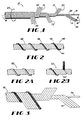
- Fig. 2 shows a flexshaft 40 according to a preferred embodiment of the present invention.
- Flexshaft 40 contains in its outer layer, a wire 42 of noise reducing material 44 which is, in this particular embodiment, flocked yam 46.
- Flocked yam material used in the flexshaft of Fig. 2 is conventional flocked yam provided by Flockgam, GmBH of Germany, under the name Nylon Flock Yam.
- Noise reducing material 44 may include any material that effectively reduces noise when a flexshaft rotates within its casing; such material includes: flocked yarn, plastic monofilament, malleable metal material, and synthetic or natural yam such as is, for instance, used in carpeting.
- the noise reducing material 44 preferably stands proud of outer layer 48 when the shaft is rotating at design speed; this may be accomplished by ensuring that the noise reducing material 44 has a diameter greater than that of other wires 14 in the outer layer 48, or it may be accomplished by providing a noise reducing material 44 which even if it does not feature such a diameter, increases in dimension such as axially to the flexshaft when the flexshaft is rotating in order to stand proud of the outer layer 48. It is possible for noise reducing material 44 to impose significant friction between the flexshaft and the casing and yet perform acceptably in applications such as power seating where the flexshaft does not rotate for lengthy periods of time.
- Fig. 2A shows a flexshaft 50 with noise reducing material 44 shown generically.
- Fig. 2B shows the noise reducing material 44 being wound onto the flexshaft 60 as part of the outer layer 62 of the flexshaft.
- Noise reducing material 44 may be wound or otherwise applied (such as extruding or otherwise forming it onto the flexshaft) as part of a separate operation; in such cases, a gap for a spare wire may be left as the outer layer 62 is being formed.
- the noise reducing material 44 is then wound onto the flexshaft 60 later, to form part of layer 62.
- Fig. 3 shows more particularly the structure of the flexshaft 40 of Fig. 2.
- Inner layer 72 contains 4 wires, each formed of .016" diameter steel wire, with a .079" pitch of approximately 35 degrees.
- the mandrel 74 is formed of .020" diameter steel wire.
- Middle layer 74 contains 6 wires, each formed of .020" diameter steel wire, with a .144" pitch of approximately 32.5 degrees.
- Outer layer 48 contains 6 wires, each formed of .028" diameter steel wire, together with one wire formed of the flock yam mentioned above, outer layer 48 having a .232" pitch of 31.6 degrees.
- FIG. 4 shows a line process according to which flexshaft according to the present invention may be made.
- a mandrel reel 80 (assuming mandrel is used) feeds a first winding station 82.
- the mandrel travels through the center of a rotating head that rotates longitudinally about the mandrel to simultaneously guide and wind the wires in the inner layer onto the mandrel.
- the rotating head is fed by a spool of wire for each of the wires in the layer, the spools axially aligned with the rotating head; if there are 6 wires in the layer, for instance, 6 spools are contained in the rotating head, the mandrel traveling longitudinally through the center of each spool.
- the tension on the wires may be adjusted by applying controlled pressure to the spools, and the speed of the head may be adjusted as desired.
- Such winding station 82 is conventional, as is the line process with the exception of applying noise reducing material 44 according to the present invention.
- the flexshaft-in-process proceeds to a second winding station 84 which applies the second layer of wires in a manner similar to the first layer, except that the rotational direction of the rotating head in the second station 84 is opposite to that of the head in the first station 82.
- the flexshaft-in-process then proceeds to third winding station 86 and additional winding stations as necessary to apply successive layers of wire.
- the flexshaft may be heat treated using radiofrequency induction or any other desired process, cooled in a cooling tube, and then taken up on take-up reel 86.
- the noise reducing material 44 may contained on a spool in the rotating head of the last winding station, and wound onto the flexshaft-in-process along with the other wires in the outer layer.
- the last winding station may be set up to leave a gap in the outer layer which is subsequently filled with noise reducing material 44 in a step subsequent to the last winding station.
- the gap may be filled by winding noise reducing material 44 onto the flexshaft in the outer layer, extruding it into the outer layer, or otherwise applying it.
- the shaft including the noise reducing material 44 is heat treated or the material is adhered with adhesive in order to cause noise reducing material 44 to be more stably attached to the flexshaft.
- flocked yam is bonded into the outer layer at a temperature of approximately 200 degrees Fahrenheit, for a period of approximately two seconds.
- the ends of flexshaft according to the present invention may be squared or otherwise formed to be received in or cooperate with mating components in a gear assembly, motor shaft, or wherever the shaft receives or delivers a load.
- the flexshaft with the noise reducing material in the outer layer is inserted into a former and pressure applied to impose onto the end, including wires and noise reducing material in the outer layer, the desired shape.
- Fig. 5 shows flexshaft 40 of Fig. 2 encased in casing 90 material suitable for vehicle power seat applications.
- Casing 90 is formed of coextruded pvc material, soft pvc inside, hard pvc outside, and features an inner diameter which is slightly larger than the diameter of the flexshaft 40 , so that the flocking material on the flocked yarn 46 is deformed at least to some extent between the flexshaft and the casing 90.
- Casing may be formed of low density polypropylene, low density polyethylene, soft or hard pvc, nylon, thermoplastic rubber, or any other desired material. The material is preferably, but need not be, plastic.
- Fig. 6 shows a flexshaft 100 with casing 102 included in a power transmission assembly 104 for transmission of power rotationally.
- the flexshaft 100 may be actuated using an electric motor 106, and in turn actuate a driven component such as a gear assembly 108. All of these components are conventional, except that this transmission assembly 104 emitted greater noise before flexshaft according to the present invention was employed.
- Fig. 7 shows a power transmission assembly according to the present invention more generically.
- a flexshaft 110 according to the present invention in a casing 112 is connected to a master unit 114 from which it receives power, and to a slave unit 116 to which it delivers power.
- Flexshaft according to the present invention may be used in any desired power transmission assembly.
- Fig. 8 shows a flexshaft 120 and power transmission assembly 122 according to the present invention employed to power vehicle seats.
- multiple motors may be used, at least some to actuate seat adjustment components via flexshaft 120 and casing 124 according to the present invention.
- a forward and aft adjustment mechanism is powered by a motor 126 which actuates gears 128 through a flexshafting 120 and casing 124 according to the present invention.
- Flexshafting 120 may also be used in power seating to connect motors with adjustment mechanisms for front tilt, lumbar adjustment, rear tilt and back tilt, among other adjustments. Any desired actuators may be used, including electric motors, hydraulic motors, or handwheels in the vehide assemblies mentioned above or below.
- Fig. 8 also shows a flexshaft 130 used to transmit power in a vehicle pedal adjustment assembly.
- an actuator 132 actuates an adjustment mechanism 134 via flexshaft 130 housed in a casing 136 in order to allow the vehicle operator to adjust the spacing of one or more pedals relative to the seat and his/her feet.
- Fig. 8 also shows a flexshaft 140 used to transmit power in a vehicle steering wheel adjustment assembly.
- an actuator 142 actuates an adjustment mechanism 144 via flexshaft 140 housed in a casing 146 in order to allow the vehicle operator to adjust the spacing and/or tilt of the steering wheel relative to the operator.
- These seat, pedal and steering wheel adjustment assemblies may be controlled via an automatic system which includes processing, memory and input/output functionality that "remembers" the preferred settings for particular vehicle operators and causes automatic adjustment to those settings on command.
- an automatic system which includes processing, memory and input/output functionality that "remembers" the preferred settings for particular vehicle operators and causes automatic adjustment to those settings on command.
- the result is power adjustment with a quieter environment through reduction of noise previously caused by rapidly spinning flexshaft.
- the flexshaft was subjected to a wind direction break test and an unwind direction break test as follows: an 8" length of the flexshaft was placed in a standard break tester and torque applied manually until at least one wire in the flexshaft failed. In all cases, because the noise reducing material adds negligable strength, the wind break point was approximately 25 inch pounds, while the unwind break point was approximately 17 inch pounds.
- Each flexshaft was then subjected to a noise test as follows: The flexshaft was placed in a soft pvc casing (.190" inside diameter, .470" outer diameter, coextruded inner diameter of soft pvc, outer diameter of hard pvc). The flexshaft was connected to a 12 vdc electric motor and rotated in a counterclockwise direction at approximately 3000 revolutions per minute. Asper Scientific #840029 noise meter, comprising a microphone connected to a VU meter, was placed so that the microphone was positioned approximately 3 inches below the casing. The sound level from the casing with rotating shafat was then measured, for each shaft with noise reducing material listed in Table 2 above and 3 below.
- the 30 - 80 dB scale was used to measure peak noise, A setting with proper calibration. All of these components were placed in a wooden test box, to isolate noise. The box measured 33.25" x 31.25” x 18", with a small open rectangular window in the top and one end. Two rounds of testing were conducted, on two occasions; the differences in noise level reflect different positioning of the microphone. The results of the tests are as follows:
- Fibrous yams with loosely wound multi-layer plies seem to be very effective as noise reducing material in accordance with the present invention, especially if a light coat of lubricant is applied. Test results show only minor variations in the noise reducing effect of similarly constructed yams. Softness seems to matter in reducing noise as a general matter.
- the loose wound yam constructions can generally be said to dampen noise or act as noise reducing material better than yams with tight wound construction, although both categories perform effectively within the meaning of noise reduction material of the present invention.
- Noise in flexshaft / casing assemblies seems to be generated as the shaft begins to vibrate inside the casing during rotation. This vibration is conjectured to be a result of, among other things, friction between the shaft and the inner diameter of the casing, and the inside diameter of the casing being out of round, even if only slightly. Once the vibration begins, the shaft must be essentially stopped to eliminate the noise.
Landscapes
- Engineering & Computer Science (AREA)
- General Engineering & Computer Science (AREA)
- Mechanical Engineering (AREA)
- Health & Medical Sciences (AREA)
- Oral & Maxillofacial Surgery (AREA)
- Chemical & Material Sciences (AREA)
- Combustion & Propulsion (AREA)
- Transportation (AREA)
- Flexible Shafts (AREA)
Priority Applications (3)
| Application Number | Priority Date | Filing Date | Title |
|---|---|---|---|
| AT01810799T ATE547638T1 (de) | 2001-08-20 | 2001-08-20 | Biegsame welle mit geräuschminderdem teil |
| EP01810799A EP1286065B1 (fr) | 2001-08-20 | 2001-08-20 | Arbre flexible avec un composant pour la réduction de bruit |
| ES01810799T ES2381262T3 (es) | 2001-08-20 | 2001-08-20 | Arbol flexible con un componente para la reducción de ruido. |
Applications Claiming Priority (1)
| Application Number | Priority Date | Filing Date | Title |
|---|---|---|---|
| EP01810799A EP1286065B1 (fr) | 2001-08-20 | 2001-08-20 | Arbre flexible avec un composant pour la réduction de bruit |
Publications (2)
| Publication Number | Publication Date |
|---|---|
| EP1286065A1 true EP1286065A1 (fr) | 2003-02-26 |
| EP1286065B1 EP1286065B1 (fr) | 2012-02-29 |
Family
ID=8184096
Family Applications (1)
| Application Number | Title | Priority Date | Filing Date |
|---|---|---|---|
| EP01810799A Expired - Lifetime EP1286065B1 (fr) | 2001-08-20 | 2001-08-20 | Arbre flexible avec un composant pour la réduction de bruit |
Country Status (3)
| Country | Link |
|---|---|
| EP (1) | EP1286065B1 (fr) |
| AT (1) | ATE547638T1 (fr) |
| ES (1) | ES2381262T3 (fr) |
Cited By (18)
| Publication number | Priority date | Publication date | Assignee | Title |
|---|---|---|---|---|
| WO2004083659A3 (fr) * | 2003-03-11 | 2004-11-18 | Inderflex Technoflex | Dispositif de transmission d'un mouvement de rotation au moyen d'un arbre flexible lisse par rectification |
| FR2855797A1 (fr) * | 2003-06-06 | 2004-12-10 | Inderflex Technoflex | Arbre flexible a fil d'ame a elasticite reduite |
| US7080869B2 (en) | 2002-11-18 | 2006-07-25 | Inderflex-Technoflex | Rotation transmission device comprising bearing-forming zones |
| DE102005033817A1 (de) * | 2005-07-20 | 2007-01-25 | Faurecia Autositze Gmbh & Co. Kg | Flexible Welle für eine Sitzverstelleinrichtung |
| US7472939B2 (en) | 2003-03-11 | 2009-01-06 | Inderflex-Technoflex | Device for transmitting a rotational movement by means of a smooth shaft |
| WO2009030376A1 (fr) * | 2007-08-30 | 2009-03-12 | W.H. Küster Gmbh & Co. Kg | Câble hélicoïdal à fil floconneux |
| EP2236844A2 (fr) | 2009-04-03 | 2010-10-06 | S.S. White Technologies Inc. | Extrémités d'arbre rotatif à faible bruit d'interface |
| CN101956754A (zh) * | 2009-07-17 | 2011-01-26 | 上海高齐汽车配件有限公司 | 一种降低噪音用天窗植绒软轴及其制备方法 |
| DE102010006945A1 (de) * | 2010-02-04 | 2011-08-04 | Küster Holding GmbH, 35630 | Mechanisch flexibler Betätigungszug |
| DE102011002182A1 (de) * | 2011-04-20 | 2012-10-25 | W.H. Küster GmbH & Co KG | Flexible Litze sowie Vorrichtung und Verfahren zum Herstellen einer flexiblen Litze |
| US8382596B2 (en) | 2009-04-03 | 2013-02-26 | S. S. White Technologies Inc. | Low noise flexible shaft |
| CN103307085A (zh) * | 2012-03-07 | 2013-09-18 | 舒能(苏州)工业技术有限公司 | 螺旋纹植绒软轴及其制备方法 |
| CN103307086A (zh) * | 2012-03-07 | 2013-09-18 | 舒能(苏州)工业技术有限公司 | 一种全植绒软轴 |
| US20140208597A1 (en) * | 2013-01-28 | 2014-07-31 | Techtronic Outdoor Products Technology Limited | Vegetation trimmer |
| EP2781771A1 (fr) | 2013-03-19 | 2014-09-24 | S.S. White Technologies Inc. | Arbre flexible ayant une capacité d'adaptation à l'interférence |
| DE102014201320A1 (de) | 2013-11-04 | 2015-05-07 | Brose Fahrzeugteile Gmbh & Co. Kg, Coburg | Antriebswellenbaugruppe mit einer flexiblen, beflockten Antriebswelle und Verfahren zu deren Herstellung |
| EP3348849A1 (fr) | 2017-01-11 | 2018-07-18 | Gemo G. Moritz GmbH & Co. KG | Arbre souple comprenant un habillage réduisant le bruit et procédé de production d'un arbre souple comprenant un habillage réduisant le bruit |
| US20180360457A1 (en) * | 2010-09-14 | 2018-12-20 | Evalve, Inc. | Flexible actuator mandrel for tissue apposition systems |
Families Citing this family (1)
| Publication number | Priority date | Publication date | Assignee | Title |
|---|---|---|---|---|
| CN105150520A (zh) * | 2015-08-18 | 2015-12-16 | 上海硅瑞恒汽车部件有限公司 | 具有植绒的软轴的加工工艺 |
Citations (7)
| Publication number | Priority date | Publication date | Assignee | Title |
|---|---|---|---|---|
| US3389579A (en) | 1965-04-02 | 1968-06-25 | Vdo Schindling | Shaft guided in a protection tube |
| GB1203191A (en) * | 1968-01-25 | 1970-08-26 | Vdo Schindling | Shaft guided in a protective guideway |
| DE2809368A1 (de) * | 1978-03-04 | 1979-09-13 | Rockwell Golde Gmbh | Kabel fuer fernbetaetigungsvorrichtungen, insbesondere kraftfahrzeugfensterheber |
| US4441168A (en) | 1982-01-13 | 1984-04-03 | Sperry Corporation | Storage logic/array (SLA) circuit |
| US4849038A (en) * | 1986-04-26 | 1989-07-18 | Gesellschaft Fuer Steuerungstechnik Gmbh & Co. | Method for depositing an interlining on a pitched cable for reducing friction and noise |
| US4915340A (en) * | 1987-07-24 | 1990-04-10 | Asin Seiki Kabushiki Kaisha | Power seat apparatus having a low friction transmission cable |
| WO1992008061A1 (fr) * | 1990-11-02 | 1992-05-14 | Pujol Y Tarrago, S.A. | Cable transmetteur de rotation |
Family Cites Families (2)
| Publication number | Priority date | Publication date | Assignee | Title |
|---|---|---|---|---|
| US4411168A (en) * | 1981-02-18 | 1983-10-25 | Nippon Cable System, Inc. | Inner cable |
| JP3226893B2 (ja) * | 1999-03-23 | 2001-11-05 | 日本ケーブル・システム株式会社 | 防音有歯ケーブル |
-
2001
- 2001-08-20 AT AT01810799T patent/ATE547638T1/de active
- 2001-08-20 ES ES01810799T patent/ES2381262T3/es not_active Expired - Lifetime
- 2001-08-20 EP EP01810799A patent/EP1286065B1/fr not_active Expired - Lifetime
Patent Citations (7)
| Publication number | Priority date | Publication date | Assignee | Title |
|---|---|---|---|---|
| US3389579A (en) | 1965-04-02 | 1968-06-25 | Vdo Schindling | Shaft guided in a protection tube |
| GB1203191A (en) * | 1968-01-25 | 1970-08-26 | Vdo Schindling | Shaft guided in a protective guideway |
| DE2809368A1 (de) * | 1978-03-04 | 1979-09-13 | Rockwell Golde Gmbh | Kabel fuer fernbetaetigungsvorrichtungen, insbesondere kraftfahrzeugfensterheber |
| US4441168A (en) | 1982-01-13 | 1984-04-03 | Sperry Corporation | Storage logic/array (SLA) circuit |
| US4849038A (en) * | 1986-04-26 | 1989-07-18 | Gesellschaft Fuer Steuerungstechnik Gmbh & Co. | Method for depositing an interlining on a pitched cable for reducing friction and noise |
| US4915340A (en) * | 1987-07-24 | 1990-04-10 | Asin Seiki Kabushiki Kaisha | Power seat apparatus having a low friction transmission cable |
| WO1992008061A1 (fr) * | 1990-11-02 | 1992-05-14 | Pujol Y Tarrago, S.A. | Cable transmetteur de rotation |
Cited By (31)
| Publication number | Priority date | Publication date | Assignee | Title |
|---|---|---|---|---|
| US7080869B2 (en) | 2002-11-18 | 2006-07-25 | Inderflex-Technoflex | Rotation transmission device comprising bearing-forming zones |
| WO2004083659A3 (fr) * | 2003-03-11 | 2004-11-18 | Inderflex Technoflex | Dispositif de transmission d'un mouvement de rotation au moyen d'un arbre flexible lisse par rectification |
| EP1500830A1 (fr) * | 2003-03-11 | 2005-01-26 | Inderflex - Technoflex | Dispositif de transmission d'un mouvement de rotation au moyen d'un arbre flexible lissé par rectification |
| US7472939B2 (en) | 2003-03-11 | 2009-01-06 | Inderflex-Technoflex | Device for transmitting a rotational movement by means of a smooth shaft |
| FR2855797A1 (fr) * | 2003-06-06 | 2004-12-10 | Inderflex Technoflex | Arbre flexible a fil d'ame a elasticite reduite |
| EP1491779A1 (fr) * | 2003-06-06 | 2004-12-29 | Inderflex-Technoflex | Arbre flexible à fil d'ame à élasticité reduite |
| WO2004111474A3 (fr) * | 2003-06-06 | 2005-04-07 | Inderflex Technoflex | Arbre flexible a fil d’ame a elasticite inferieure a celle des fils d’enroulement |
| US7367605B2 (en) | 2003-06-06 | 2008-05-06 | Inderflex-Technoflex | Flexible shaft whose core yarn elasticity is less than that of wound yarn |
| DE102005033817A1 (de) * | 2005-07-20 | 2007-01-25 | Faurecia Autositze Gmbh & Co. Kg | Flexible Welle für eine Sitzverstelleinrichtung |
| DE102005033817B4 (de) * | 2005-07-20 | 2007-07-05 | Faurecia Autositze Gmbh | Fahrzeugsitzverstellvorrichtung mit mindestens einer flexiblen Welle |
| WO2009030376A1 (fr) * | 2007-08-30 | 2009-03-12 | W.H. Küster Gmbh & Co. Kg | Câble hélicoïdal à fil floconneux |
| US8162761B2 (en) | 2009-04-03 | 2012-04-24 | S.S. White Technologies Inc. | Low interface noise rotary shaft tips |
| US8382596B2 (en) | 2009-04-03 | 2013-02-26 | S. S. White Technologies Inc. | Low noise flexible shaft |
| EP2236844A2 (fr) | 2009-04-03 | 2010-10-06 | S.S. White Technologies Inc. | Extrémités d'arbre rotatif à faible bruit d'interface |
| CN101956754A (zh) * | 2009-07-17 | 2011-01-26 | 上海高齐汽车配件有限公司 | 一种降低噪音用天窗植绒软轴及其制备方法 |
| DE102010006945B4 (de) * | 2010-02-04 | 2014-02-20 | Küster Holding GmbH | Mechanisch flexibler Betätigungszug |
| DE102010006945A1 (de) * | 2010-02-04 | 2011-08-04 | Küster Holding GmbH, 35630 | Mechanisch flexibler Betätigungszug |
| US20180360457A1 (en) * | 2010-09-14 | 2018-12-20 | Evalve, Inc. | Flexible actuator mandrel for tissue apposition systems |
| US10925604B2 (en) | 2010-09-14 | 2021-02-23 | Evalve, Inc. | Flexible actuator mandrel for tissue apposition systems |
| EP3520715A1 (fr) * | 2010-09-14 | 2019-08-07 | Evalve, Inc. | Mandrin d'actionneur flexible pour systèmes d'apposition de tissus |
| DE102011002182B4 (de) * | 2011-04-20 | 2013-11-28 | W.H. Küster GmbH & Co KG | Flexible Litze sowie Verfahren zum Herstellen einer flexiblen Litze |
| DE102011002182A1 (de) * | 2011-04-20 | 2012-10-25 | W.H. Küster GmbH & Co KG | Flexible Litze sowie Vorrichtung und Verfahren zum Herstellen einer flexiblen Litze |
| CN103307085A (zh) * | 2012-03-07 | 2013-09-18 | 舒能(苏州)工业技术有限公司 | 螺旋纹植绒软轴及其制备方法 |
| CN103307086A (zh) * | 2012-03-07 | 2013-09-18 | 舒能(苏州)工业技术有限公司 | 一种全植绒软轴 |
| US20140208597A1 (en) * | 2013-01-28 | 2014-07-31 | Techtronic Outdoor Products Technology Limited | Vegetation trimmer |
| EP2781771A1 (fr) | 2013-03-19 | 2014-09-24 | S.S. White Technologies Inc. | Arbre flexible ayant une capacité d'adaptation à l'interférence |
| US9528544B2 (en) | 2013-11-04 | 2016-12-27 | Brose Fahrzeugteile Gmbh & Co. Kommanditgesellschaft, Coburg | Drive shaft assembly having a flexible, flocked drive shaft, and method for its manufacture |
| DE102014201320B4 (de) | 2013-11-04 | 2020-06-18 | Brose Fahrzeugteile SE & Co. Kommanditgesellschaft, Coburg | Antriebswellenbaugruppe mit einer flexiblen, beflockten Antriebswelle, Verfahren zu deren Herstellung und Schienenverstellsystem |
| DE102014201320A1 (de) | 2013-11-04 | 2015-05-07 | Brose Fahrzeugteile Gmbh & Co. Kg, Coburg | Antriebswellenbaugruppe mit einer flexiblen, beflockten Antriebswelle und Verfahren zu deren Herstellung |
| WO2018130259A1 (fr) * | 2017-01-11 | 2018-07-19 | Gemo G. Moritz Gmbh & Co. Kg | Arbre flexible présentant un enroulement réducteur de bruits et procédé de fabrication d'un arbre flexible présentant un enroulement réducteur de bruits |
| EP3348849A1 (fr) | 2017-01-11 | 2018-07-18 | Gemo G. Moritz GmbH & Co. KG | Arbre souple comprenant un habillage réduisant le bruit et procédé de production d'un arbre souple comprenant un habillage réduisant le bruit |
Also Published As
| Publication number | Publication date |
|---|---|
| EP1286065B1 (fr) | 2012-02-29 |
| ES2381262T3 (es) | 2012-05-24 |
| ATE547638T1 (de) | 2012-03-15 |
Similar Documents
| Publication | Publication Date | Title |
|---|---|---|
| EP1286065A1 (fr) | Arbre flexible avec un composant pour la réduction de bruit | |
| JP2583449B2 (ja) | 管状製品、殊にカテーテルを製造する方法 | |
| US6017335A (en) | Method for making a tubular product, especially a catheter, and article made thereby | |
| US3857415A (en) | Reinforced convoluted tubing of polytetrafluoroethylene | |
| KR920003384B1 (ko) | 복합연합형 항장력체 및 그의 제조방법 | |
| TWI296724B (en) | Communication cable, and communication wire protecting tube | |
| US10457228B2 (en) | Cable and wire harness | |
| US10569724B2 (en) | Composite cable and wire harness | |
| US10163547B2 (en) | Linear filler padded composite cable | |
| GB2133499A (en) | Shafts incorporating fibre-reinforced plastics | |
| WO2010026749A1 (fr) | Procédé de fabrication d'un tuyau en caoutchouc renforcé par des câbles d'acier, tuyau en caoutchouc renforcé par des câbles d'acier, et matériau en bande composite | |
| US5195393A (en) | Braided mechanical control cable | |
| EP1314925B1 (fr) | Conduit flexible de frein | |
| US20090211388A1 (en) | Pull-pull type shifter control cable | |
| US7866024B2 (en) | Method of manufacture for a push-pull cable assembly | |
| US10736412B2 (en) | Flexible torsion shaft and an arrangement using it and a cleaning device for air-conditioning ducts | |
| JPH08290487A (ja) | Frp筒体の製造方法 | |
| US20100064840A1 (en) | Snap-over guide tube for a push-pull cable assembly | |
| US8413542B2 (en) | Plastic core attachment for a push-pull cable assembly | |
| AU2019222793A1 (en) | Method and apparatus for curing of pre impregnated synthetic components in situ | |
| US7367605B2 (en) | Flexible shaft whose core yarn elasticity is less than that of wound yarn | |
| US8245379B2 (en) | Snap-together, two-piece guide tube for a push-pull cable assembly | |
| CA2039924C (fr) | Fabrication de cable electrique et optique combine | |
| KR100614413B1 (ko) | 플렉시블관 제조장치 | |
| WO2026034529A1 (fr) | Câble interne et câble de commande comprenant un câble interne |
Legal Events
| Date | Code | Title | Description |
|---|---|---|---|
| PUAI | Public reference made under article 153(3) epc to a published international application that has entered the european phase |
Free format text: ORIGINAL CODE: 0009012 |
|
| AK | Designated contracting states |
Kind code of ref document: A1 Designated state(s): AT BE CH CY DE DK ES FI FR GB GR IE IT LI LU MC NL PT SE TR Designated state(s): AT BE CH CY DE DK ES FI FR GB GR IE IT LI LU MC NL PT SE TR |
|
| AX | Request for extension of the european patent |
Extension state: AL LT LV MK RO SI |
|
| 17P | Request for examination filed |
Effective date: 20030321 |
|
| AKX | Designation fees paid |
Designated state(s): AT BE CH CY DE DK ES FI FR GB GR IE IT LI LU MC NL PT SE TR |
|
| 17Q | First examination report despatched |
Effective date: 20040203 |
|
| RAP1 | Party data changed (applicant data changed or rights of an application transferred) |
Owner name: SUHNER INTERTRADE AG |
|
| 17Q | First examination report despatched |
Effective date: 20040203 |
|
| TPAC | Observations filed by third parties |
Free format text: ORIGINAL CODE: EPIDOSNTIPA |
|
| GRAP | Despatch of communication of intention to grant a patent |
Free format text: ORIGINAL CODE: EPIDOSNIGR1 |
|
| GRAS | Grant fee paid |
Free format text: ORIGINAL CODE: EPIDOSNIGR3 |
|
| GRAA | (expected) grant |
Free format text: ORIGINAL CODE: 0009210 |
|
| AK | Designated contracting states |
Kind code of ref document: B1 Designated state(s): AT BE CH CY DE DK ES FI FR GB GR IE IT LI LU MC NL PT SE TR |
|
| REG | Reference to a national code |
Ref country code: GB Ref legal event code: FG4D Ref country code: CH Ref legal event code: EP Ref country code: CH Ref legal event code: NV Representative=s name: HANS RUDOLF GACHNANG PATENTANWALT |
|
| REG | Reference to a national code |
Ref country code: AT Ref legal event code: REF Ref document number: 547638 Country of ref document: AT Kind code of ref document: T Effective date: 20120315 |
|
| REG | Reference to a national code |
Ref country code: IE Ref legal event code: FG4D |
|
| REG | Reference to a national code |
Ref country code: DE Ref legal event code: R096 Ref document number: 60146184 Country of ref document: DE Effective date: 20120419 |
|
| REG | Reference to a national code |
Ref country code: ES Ref legal event code: FG2A Ref document number: 2381262 Country of ref document: ES Kind code of ref document: T3 Effective date: 20120524 |
|
| REG | Reference to a national code |
Ref country code: NL Ref legal event code: VDEP Effective date: 20120229 |
|
| PG25 | Lapsed in a contracting state [announced via postgrant information from national office to epo] |
Ref country code: NL Free format text: LAPSE BECAUSE OF FAILURE TO SUBMIT A TRANSLATION OF THE DESCRIPTION OR TO PAY THE FEE WITHIN THE PRESCRIBED TIME-LIMIT Effective date: 20120229 |
|
| PG25 | Lapsed in a contracting state [announced via postgrant information from national office to epo] |
Ref country code: BE Free format text: LAPSE BECAUSE OF FAILURE TO SUBMIT A TRANSLATION OF THE DESCRIPTION OR TO PAY THE FEE WITHIN THE PRESCRIBED TIME-LIMIT Effective date: 20120229 Ref country code: PT Free format text: LAPSE BECAUSE OF FAILURE TO SUBMIT A TRANSLATION OF THE DESCRIPTION OR TO PAY THE FEE WITHIN THE PRESCRIBED TIME-LIMIT Effective date: 20120629 Ref country code: FI Free format text: LAPSE BECAUSE OF FAILURE TO SUBMIT A TRANSLATION OF THE DESCRIPTION OR TO PAY THE FEE WITHIN THE PRESCRIBED TIME-LIMIT Effective date: 20120229 Ref country code: GR Free format text: LAPSE BECAUSE OF FAILURE TO SUBMIT A TRANSLATION OF THE DESCRIPTION OR TO PAY THE FEE WITHIN THE PRESCRIBED TIME-LIMIT Effective date: 20120530 |
|
| PG25 | Lapsed in a contracting state [announced via postgrant information from national office to epo] |
Ref country code: CY Free format text: LAPSE BECAUSE OF FAILURE TO SUBMIT A TRANSLATION OF THE DESCRIPTION OR TO PAY THE FEE WITHIN THE PRESCRIBED TIME-LIMIT Effective date: 20120229 |
|
| PG25 | Lapsed in a contracting state [announced via postgrant information from national office to epo] |
Ref country code: DK Free format text: LAPSE BECAUSE OF FAILURE TO SUBMIT A TRANSLATION OF THE DESCRIPTION OR TO PAY THE FEE WITHIN THE PRESCRIBED TIME-LIMIT Effective date: 20120229 Ref country code: SE Free format text: LAPSE BECAUSE OF FAILURE TO SUBMIT A TRANSLATION OF THE DESCRIPTION OR TO PAY THE FEE WITHIN THE PRESCRIBED TIME-LIMIT Effective date: 20120229 |
|
| PLBI | Opposition filed |
Free format text: ORIGINAL CODE: 0009260 |
|
| 26 | Opposition filed |
Opponent name: GEMO G. MORITZ GMBH & CO. KG Effective date: 20121129 |
|
| PLAX | Notice of opposition and request to file observation + time limit sent |
Free format text: ORIGINAL CODE: EPIDOSNOBS2 |
|
| REG | Reference to a national code |
Ref country code: DE Ref legal event code: R026 Ref document number: 60146184 Country of ref document: DE Effective date: 20121129 |
|
| PG25 | Lapsed in a contracting state [announced via postgrant information from national office to epo] |
Ref country code: MC Free format text: LAPSE BECAUSE OF NON-PAYMENT OF DUE FEES Effective date: 20120831 |
|
| PLBB | Reply of patent proprietor to notice(s) of opposition received |
Free format text: ORIGINAL CODE: EPIDOSNOBS3 |
|
| REG | Reference to a national code |
Ref country code: IE Ref legal event code: MM4A |
|
| PLAB | Opposition data, opponent's data or that of the opponent's representative modified |
Free format text: ORIGINAL CODE: 0009299OPPO |
|
| PLAB | Opposition data, opponent's data or that of the opponent's representative modified |
Free format text: ORIGINAL CODE: 0009299OPPO |
|
| R26 | Opposition filed (corrected) |
Opponent name: GEMO G. MORITZ GMBH & CO. KG Effective date: 20121129 |
|
| R26 | Opposition filed (corrected) |
Opponent name: GEMO G. MORITZ GMBH & CO. KG Effective date: 20121129 |
|
| PG25 | Lapsed in a contracting state [announced via postgrant information from national office to epo] |
Ref country code: IE Free format text: LAPSE BECAUSE OF NON-PAYMENT OF DUE FEES Effective date: 20120820 |
|
| PLBP | Opposition withdrawn |
Free format text: ORIGINAL CODE: 0009264 |
|
| PLBD | Termination of opposition procedure: decision despatched |
Free format text: ORIGINAL CODE: EPIDOSNOPC1 |
|
| REG | Reference to a national code |
Ref country code: CH Ref legal event code: NV Representative=s name: GACHNANG AG PATENTANWAELTE, CH |
|
| PLBM | Termination of opposition procedure: date of legal effect published |
Free format text: ORIGINAL CODE: 0009276 |
|
| STAA | Information on the status of an ep patent application or granted ep patent |
Free format text: STATUS: OPPOSITION PROCEDURE CLOSED |
|
| PG25 | Lapsed in a contracting state [announced via postgrant information from national office to epo] |
Ref country code: TR Free format text: LAPSE BECAUSE OF FAILURE TO SUBMIT A TRANSLATION OF THE DESCRIPTION OR TO PAY THE FEE WITHIN THE PRESCRIBED TIME-LIMIT Effective date: 20120229 |
|
| 27C | Opposition proceedings terminated |
Effective date: 20140124 |
|
| PG25 | Lapsed in a contracting state [announced via postgrant information from national office to epo] |
Ref country code: LU Free format text: LAPSE BECAUSE OF NON-PAYMENT OF DUE FEES Effective date: 20120820 |
|
| REG | Reference to a national code |
Ref country code: FR Ref legal event code: PLFP Year of fee payment: 16 |
|
| REG | Reference to a national code |
Ref country code: FR Ref legal event code: PLFP Year of fee payment: 17 |
|
| REG | Reference to a national code |
Ref country code: FR Ref legal event code: PLFP Year of fee payment: 18 |
|
| PGFP | Annual fee paid to national office [announced via postgrant information from national office to epo] |
Ref country code: ES Payment date: 20200917 Year of fee payment: 20 Ref country code: GB Payment date: 20200825 Year of fee payment: 20 Ref country code: FR Payment date: 20200820 Year of fee payment: 20 Ref country code: DE Payment date: 20200824 Year of fee payment: 20 |
|
| PGFP | Annual fee paid to national office [announced via postgrant information from national office to epo] |
Ref country code: IT Payment date: 20200831 Year of fee payment: 20 Ref country code: AT Payment date: 20200819 Year of fee payment: 20 Ref country code: CH Payment date: 20200814 Year of fee payment: 20 |
|
| REG | Reference to a national code |
Ref country code: DE Ref legal event code: R071 Ref document number: 60146184 Country of ref document: DE |
|
| REG | Reference to a national code |
Ref country code: CH Ref legal event code: PL |
|
| REG | Reference to a national code |
Ref country code: GB Ref legal event code: PE20 Expiry date: 20210819 |
|
| REG | Reference to a national code |
Ref country code: AT Ref legal event code: MK07 Ref document number: 547638 Country of ref document: AT Kind code of ref document: T Effective date: 20210820 |
|
| REG | Reference to a national code |
Ref country code: ES Ref legal event code: FD2A Effective date: 20211126 |
|
| PG25 | Lapsed in a contracting state [announced via postgrant information from national office to epo] |
Ref country code: GB Free format text: LAPSE BECAUSE OF EXPIRATION OF PROTECTION Effective date: 20210819 |
|
| PG25 | Lapsed in a contracting state [announced via postgrant information from national office to epo] |
Ref country code: ES Free format text: LAPSE BECAUSE OF EXPIRATION OF PROTECTION Effective date: 20210821 |