EP1286080A2 - Dispositif de changement de vitesse pour transmission - Google Patents
Dispositif de changement de vitesse pour transmission Download PDFInfo
- Publication number
- EP1286080A2 EP1286080A2 EP02014751A EP02014751A EP1286080A2 EP 1286080 A2 EP1286080 A2 EP 1286080A2 EP 02014751 A EP02014751 A EP 02014751A EP 02014751 A EP02014751 A EP 02014751A EP 1286080 A2 EP1286080 A2 EP 1286080A2
- Authority
- EP
- European Patent Office
- Prior art keywords
- sliding sleeve
- ring
- elevation
- sliding
- recess
- Prior art date
- Legal status (The legal status is an assumption and is not a legal conclusion. Google has not performed a legal analysis and makes no representation as to the accuracy of the status listed.)
- Withdrawn
Links
Images


Classifications
-
- F—MECHANICAL ENGINEERING; LIGHTING; HEATING; WEAPONS; BLASTING
- F16—ENGINEERING ELEMENTS AND UNITS; GENERAL MEASURES FOR PRODUCING AND MAINTAINING EFFECTIVE FUNCTIONING OF MACHINES OR INSTALLATIONS; THERMAL INSULATION IN GENERAL
- F16H—GEARING
- F16H63/00—Control outputs from the control unit to change-speed- or reversing-gearings for conveying rotary motion or to other devices than the final output mechanism
- F16H63/02—Final output mechanisms therefor; Actuating means for the final output mechanisms
- F16H63/30—Constructional features of the final output mechanisms
-
- F—MECHANICAL ENGINEERING; LIGHTING; HEATING; WEAPONS; BLASTING
- F16—ENGINEERING ELEMENTS AND UNITS; GENERAL MEASURES FOR PRODUCING AND MAINTAINING EFFECTIVE FUNCTIONING OF MACHINES OR INSTALLATIONS; THERMAL INSULATION IN GENERAL
- F16H—GEARING
- F16H57/00—General details of gearing
- F16H57/02—Gearboxes; Mounting gearing therein
- F16H2057/02086—Measures for reducing size of gearbox, e.g. for creating a more compact transmission casing
-
- F—MECHANICAL ENGINEERING; LIGHTING; HEATING; WEAPONS; BLASTING
- F16—ENGINEERING ELEMENTS AND UNITS; GENERAL MEASURES FOR PRODUCING AND MAINTAINING EFFECTIVE FUNCTIONING OF MACHINES OR INSTALLATIONS; THERMAL INSULATION IN GENERAL
- F16H—GEARING
- F16H63/00—Control outputs from the control unit to change-speed- or reversing-gearings for conveying rotary motion or to other devices than the final output mechanism
- F16H63/02—Final output mechanisms therefor; Actuating means for the final output mechanisms
- F16H63/30—Constructional features of the final output mechanisms
- F16H2063/3093—Final output elements, i.e. the final elements to establish gear ratio, e.g. coupling sleeves or other means establishing coupling to shaft
-
- Y—GENERAL TAGGING OF NEW TECHNOLOGICAL DEVELOPMENTS; GENERAL TAGGING OF CROSS-SECTIONAL TECHNOLOGIES SPANNING OVER SEVERAL SECTIONS OF THE IPC; TECHNICAL SUBJECTS COVERED BY FORMER USPC CROSS-REFERENCE ART COLLECTIONS [XRACs] AND DIGESTS
- Y10—TECHNICAL SUBJECTS COVERED BY FORMER USPC
- Y10T—TECHNICAL SUBJECTS COVERED BY FORMER US CLASSIFICATION
- Y10T74/00—Machine element or mechanism
- Y10T74/19—Gearing
- Y10T74/19219—Interchangeably locked
- Y10T74/19251—Control mechanism
Definitions
- the present invention relates to a gear shift device according to the Preamble of claim 1.
- a transmission in which a first and a second switchable gear rotatably mounted on an input shaft are.
- a fixed sleeve is arranged between the two gear wheels is rotatably connected to the input shaft. It is axially displaceable on the fixed sleeve a sliding sleeve arranged, which occupy three switch positions can, namely a middle or neutral position and a first or second switching position in which the first or second gear on the Sliding sleeve and the fixed sleeve is rotatably connected to the shaft.
- to Operation of the sliding sleeve is circumferential on its outer circumference Groove provided, in which a shift fork connected to a shift rod intervenes, which can be operated by the driver via a gear lever.
- a gear shifted, by a positive connection between a gear and the associated Shaft is manufactured. Is the "connection” between the gear and the shaft is closed, a torque can be generated via this "path” be transmitted.
- a “connecting element” has an inner part or a fixed sleeve with an external toothing arranged in the axial direction Teeth, as well as an axially displaceable sliding sleeve with a Internal gearing.
- the fixed sleeve and the sliding sleeve are always engaged.
- a gear wheel can be engaged by axially shifting the sliding sleeve are, that is, in the direction of rotation positively over the fixed sleeve with the Shaft are connected.
- the object of the invention is to provide a gear shift device with at least to create two adjacent switching alleys, one more has a more compact design.
- the basic principle of the invention is the distance between the adjacent Selector gates should be selected so that they are in the longitudinal direction of the selector gates projected outer circumferences of the sliding sleeves cut or overlap.
- the one in the peripheral area Sliding sleeve provided a circumferential "recess", at least part of the peripheral area of the other sliding sleeve can engage.
- the recess can be, for example, a circumferential groove-like depression his.
- the part of the other sliding sleeve that engages in the recess can be a complementary ring-like elevation.
- the width of the groove-like depression is, however, several times larger than the width of the ring-like elevation, so that an axial relative displacement of the two Sliding sleeves, i.e. switching one shift gate independently from the other shift gate is possible.
- both sliding sleeves have on their Outer peripheral area each have a circumferential ring-like elevation forms an axial "end stop" for the other sliding sleeve.
- the ring-like elevations of the two sliding sleeves are preferred arranged off-center.
- the ring-like elevation is the a sliding sleeve near the front or left axial end of this Sliding sleeve arranged and the ring-like elevation of the others Sliding sleeve is near the rear or right axial end of the other Sliding sleeve arranged.
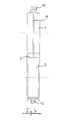
- FIG. 1 shows a first sliding sleeve 1 and a second sliding sleeve 2, each of which is assigned to a "shift gate” indicated by dotted lines.
- the sliding sleeves 1, 2 are axially displaceable along the respective shift gate longitudinal direction 3, 4.
- circumferential groove-like depressions 5, 6 are provided on their outer circumference, into which associated shift forks 7, 8 engage, which can be actuated, for example, by means of a shift rod.
- a shift rocker can also be provided.
- the distance A of the two shift gates is limited by the diameter of the shift sleeves 1, 2, or for a predetermined shift gate distance A, the diameters of the shift sleeves 1, 2 are limited, since at least a small distance is provided between their outer circumferences got to.
- Figure 2a shows an embodiment in which a circumferential ring-like elevation 9 is provided centrally on the outer circumference of the sliding sleeve 1. Similar to FIG. 1, the sliding sleeve 2 has a circumferential groove-like depression 6.
- the shift sleeves 1, 2 are dimensioned and arranged here so that the ring-like elevation 9 of the sliding sleeve 1 "engages" in the groove-like recess 6 of the sliding sleeve 2.
- the axial projections of the sliding sleeves 1, 2 thus overlap.
- the width B of the groove-like recess 6 of the sliding sleeve 2 is several times larger than the width b of the ring-like elevation 9 of the sliding sleeve 1. This enables an axial relative displacement of the sliding sleeve 1 with respect to the sliding sleeve 2, which is shown in FIG. 2b .
- the shift gate assigned to the sliding sleeve 1 can thus be switched within the "shift width B" regardless of the switching state of the sliding sleeve 2.
- Figures 3a and 3b show an embodiment in which a circumferential ring-like elevation 9, 10 is provided on each of the two sliding sleeves 1, 2.
- the ring-like elevation 9 of the sliding sleeve 1 is offset to the “right” with respect to the central plane of the sliding sleeve 1, ie is arranged off-center.
- the ring-like elevation 10 of the sliding sleeve 2 is offset to the "left" with respect to the central plane of the sliding sleeve 2.
- the displacement path of the sliding sleeve 1 or 2 is in each case only limited in one direction by the other sliding sleeve 1 or 2.
- the ring-like elevations 9, 10 of the sliding sleeves 1, 2 each form an “end stop” for the other sliding sleeve.
- the sliding sleeves 1, 2 with their ring-like elevations 9, 10 also "engage” with one another, ie overlap, larger sliding sleeve diameters or larger synchronizer ring diameters can be realized in comparison with the prior art.
- FIG 4 shows an embodiment corresponding to Figures 2a, 2b.
- sliding elements for moving the sliding sleeves 1, 2 are also shown.
- the sliding element for the sliding sleeve 1 is a clip-like, slotted shift fork 11 which engages over the ring-like elevation 9.
- the displacement element of the sliding sleeve 2 is a conventional shift fork or a conventional rocker arm 12, which engages in the groove-like recess 6.
- the bracket-like shift fork 11 and the shift fork 12 can be connected to a shift rod in a conventional manner.
Landscapes
- Engineering & Computer Science (AREA)
- General Engineering & Computer Science (AREA)
- Mechanical Engineering (AREA)
- Gear-Shifting Mechanisms (AREA)
Applications Claiming Priority (2)
| Application Number | Priority Date | Filing Date | Title |
|---|---|---|---|
| DE10139512A DE10139512A1 (de) | 2001-08-10 | 2001-08-10 | Getriebeschaltvorrichtung |
| DE10139512 | 2001-08-10 |
Publications (1)
| Publication Number | Publication Date |
|---|---|
| EP1286080A2 true EP1286080A2 (fr) | 2003-02-26 |
Family
ID=7695142
Family Applications (1)
| Application Number | Title | Priority Date | Filing Date |
|---|---|---|---|
| EP02014751A Withdrawn EP1286080A2 (fr) | 2001-08-10 | 2002-07-04 | Dispositif de changement de vitesse pour transmission |
Country Status (4)
| Country | Link |
|---|---|
| US (1) | US20030041682A1 (fr) |
| EP (1) | EP1286080A2 (fr) |
| JP (1) | JP2003056698A (fr) |
| DE (1) | DE10139512A1 (fr) |
Family Cites Families (4)
| Publication number | Priority date | Publication date | Assignee | Title |
|---|---|---|---|---|
| JPS5566009A (en) * | 1978-11-08 | 1980-05-19 | Nissan Motor Co Ltd | Coupling sleeve |
| US5105674A (en) * | 1990-09-19 | 1992-04-21 | Borg-Warner Automotive Diversified Transmission Products Corporation | Constant-mesh, multiple-shaft transmission |
| US5280731A (en) * | 1992-11-10 | 1994-01-25 | Borg-Warner Automotive, Inc. | Constant-mesh transmission with a chain drive and double disconnect reverse |
| DE19820654B4 (de) * | 1998-05-08 | 2006-11-23 | Schaeffler Kg | Schiebemuffe einer Synchronisiereinheit für Schaltgetriebe |
-
2001
- 2001-08-10 DE DE10139512A patent/DE10139512A1/de not_active Withdrawn
-
2002
- 2002-07-04 EP EP02014751A patent/EP1286080A2/fr not_active Withdrawn
- 2002-08-08 JP JP2002231695A patent/JP2003056698A/ja active Pending
- 2002-08-09 US US10/215,191 patent/US20030041682A1/en not_active Abandoned
Also Published As
| Publication number | Publication date |
|---|---|
| DE10139512A1 (de) | 2003-03-06 |
| US20030041682A1 (en) | 2003-03-06 |
| JP2003056698A (ja) | 2003-02-26 |
Similar Documents
| Publication | Publication Date | Title |
|---|---|---|
| DE2952586C2 (de) | Schalteinrichtung für ein Vorgelegegetriebe | |
| DE102014118432B4 (de) | Getriebe | |
| DE3150885C2 (fr) | ||
| DE2930151A1 (de) | Gangwahlmechanismus und diesen enthaltendes getriebe | |
| DE10316163A1 (de) | Mehrstufiges Schaltgetriebe für eine Brennkraftmaschine | |
| DE3536088C2 (fr) | ||
| EP2232107B1 (fr) | Dispositif de changement de vitesse pour boîtes de vitesses à plusieurs étages de véhicules automobiles | |
| EP2529133B1 (fr) | Dispositif de protection de changement de vitesses d'une boîte de vitesses à rapports multiples | |
| DE1904663A1 (de) | Handgeschaltetes Getriebe fuer Kraftfahrzeuge mit zwei Antriebsbereichen | |
| DE4424543B4 (de) | Schalthebelanordnung für ein Getriebe | |
| EP0999384A1 (fr) | Dispositif de changement de vitesse pour une boíte de vitesse d'un véhicule automobile | |
| DE2341199A1 (de) | Schalteinrichtung fuer mechanische wechselgetriebe von kraftfahrzeugen | |
| DE3314413C2 (fr) | ||
| EP2850341B1 (fr) | Ensemble de transmission | |
| EP0928725B1 (fr) | Installation de frein de stationnement pour véhicules avec engrenage de changement vitesse | |
| WO2005078320A1 (fr) | Dispositif de commutation a une seule tringle sur une boite de vitesses | |
| DE102014115371B4 (de) | Schaltanordnung für ein Kraftfahrzeuggetriebe und Schaltverfahren | |
| EP1291560A2 (fr) | Dispositif de changement de rapports à commande assistée | |
| DE202004006953U1 (de) | Schalteinrichtung für ein Wechselgetriebe mit vereinfachter Schaltkulisse | |
| DE102013202272A1 (de) | Schalteinrichtung mit einer Schalt- und Wählwelle für ein Fahrzeuggetriebe | |
| DE102018206392A1 (de) | Schalteinrichtung zur durchführung von gangwechseln in einem fahrzeuggetriebe | |
| EP1286080A2 (fr) | Dispositif de changement de vitesse pour transmission | |
| EP1310707B1 (fr) | Dispositif de changement de vitesses et méthode de mouvement et guidage de fourchettes dans une transmission à changement de vitesses | |
| DE60006457T2 (de) | Getriebe kompakter Bauart mit Schwenkfüssen zur Betätigung von Schaltgabeln | |
| DE19581879B4 (de) | Planetengetriebe |
Legal Events
| Date | Code | Title | Description |
|---|---|---|---|
| PUAI | Public reference made under article 153(3) epc to a published international application that has entered the european phase |
Free format text: ORIGINAL CODE: 0009012 |
|
| AK | Designated contracting states |
Kind code of ref document: A2 Designated state(s): AT BE BG CH CY CZ DE DK EE ES FI FR GB GR IE IT LI LU MC NL PT SE SK TR Designated state(s): AT BE BG CH CY CZ DE DK EE ES FI FR GB GR IE IT LI LU MC NL PT SE SK TR |
|
| AX | Request for extension of the european patent |
Extension state: AL LT LV MK RO SI |
|
| STAA | Information on the status of an ep patent application or granted ep patent |
Free format text: STATUS: THE APPLICATION HAS BEEN WITHDRAWN |
|
| 18W | Application withdrawn |
Effective date: 20041018 |