EP1286415B1 - Procédé de suppression de signaux de brouillage - Google Patents
Procédé de suppression de signaux de brouillage Download PDFInfo
- Publication number
- EP1286415B1 EP1286415B1 EP02014487A EP02014487A EP1286415B1 EP 1286415 B1 EP1286415 B1 EP 1286415B1 EP 02014487 A EP02014487 A EP 02014487A EP 02014487 A EP02014487 A EP 02014487A EP 1286415 B1 EP1286415 B1 EP 1286415B1
- Authority
- EP
- European Patent Office
- Prior art keywords
- sub
- burst
- sidelobe
- sum
- jammer
- Prior art date
- Legal status (The legal status is an assumption and is not a legal conclusion. Google has not performed a legal analysis and makes no representation as to the accuracy of the status listed.)
- Expired - Lifetime
Links
- 238000000034 method Methods 0.000 title claims description 22
- 230000001629 suppression Effects 0.000 claims description 5
- 230000009466 transformation Effects 0.000 claims description 5
- 238000001228 spectrum Methods 0.000 claims description 3
- 230000008030 elimination Effects 0.000 claims 1
- 238000003379 elimination reaction Methods 0.000 claims 1
- 230000003044 adaptive effect Effects 0.000 description 4
- 108010076504 Protein Sorting Signals Proteins 0.000 description 3
- 230000002123 temporal effect Effects 0.000 description 2
- 230000006978 adaptation Effects 0.000 description 1
- 230000001419 dependent effect Effects 0.000 description 1
- 238000005070 sampling Methods 0.000 description 1
Images

Classifications
-
- G—PHYSICS
- G01—MEASURING; TESTING
- G01S—RADIO DIRECTION-FINDING; RADIO NAVIGATION; DETERMINING DISTANCE OR VELOCITY BY USE OF RADIO WAVES; LOCATING OR PRESENCE-DETECTING BY USE OF THE REFLECTION OR RERADIATION OF RADIO WAVES; ANALOGOUS ARRANGEMENTS USING OTHER WAVES
- G01S7/00—Details of systems according to groups G01S13/00, G01S15/00, G01S17/00
- G01S7/02—Details of systems according to groups G01S13/00, G01S15/00, G01S17/00 of systems according to group G01S13/00
- G01S7/28—Details of pulse systems
- G01S7/2813—Means providing a modification of the radiation pattern for cancelling noise, clutter or interfering signals, e.g. side lobe suppression, side lobe blanking, null-steering arrays
-
- G—PHYSICS
- G01—MEASURING; TESTING
- G01S—RADIO DIRECTION-FINDING; RADIO NAVIGATION; DETERMINING DISTANCE OR VELOCITY BY USE OF RADIO WAVES; LOCATING OR PRESENCE-DETECTING BY USE OF THE REFLECTION OR RERADIATION OF RADIO WAVES; ANALOGOUS ARRANGEMENTS USING OTHER WAVES
- G01S7/00—Details of systems according to groups G01S13/00, G01S15/00, G01S17/00
- G01S7/02—Details of systems according to groups G01S13/00, G01S15/00, G01S17/00 of systems according to group G01S13/00
- G01S7/28—Details of pulse systems
- G01S7/285—Receivers
-
- H—ELECTRICITY
- H01—ELECTRIC ELEMENTS
- H01Q—ANTENNAS, i.e. RADIO AERIALS
- H01Q3/00—Arrangements for changing or varying the orientation or the shape of the directional pattern of the waves radiated from an antenna or antenna system
- H01Q3/26—Arrangements for changing or varying the orientation or the shape of the directional pattern of the waves radiated from an antenna or antenna system varying the relative phase or relative amplitude of energisation between two or more active radiating elements; varying the distribution of energy across a radiating aperture
- H01Q3/2605—Array of radiating elements provided with a feedback control over the element weights, e.g. adaptive arrays
- H01Q3/2611—Means for null steering; Adaptive interference nulling
- H01Q3/2629—Combination of a main antenna unit with an auxiliary antenna unit
- H01Q3/2635—Combination of a main antenna unit with an auxiliary antenna unit the auxiliary unit being composed of a plurality of antennas
-
- G—PHYSICS
- G01—MEASURING; TESTING
- G01S—RADIO DIRECTION-FINDING; RADIO NAVIGATION; DETERMINING DISTANCE OR VELOCITY BY USE OF RADIO WAVES; LOCATING OR PRESENCE-DETECTING BY USE OF THE REFLECTION OR RERADIATION OF RADIO WAVES; ANALOGOUS ARRANGEMENTS USING OTHER WAVES
- G01S7/00—Details of systems according to groups G01S13/00, G01S15/00, G01S17/00
- G01S7/02—Details of systems according to groups G01S13/00, G01S15/00, G01S17/00 of systems according to group G01S13/00
- G01S7/36—Means for anti-jamming, e.g. ECCM, i.e. electronic counter-counter measures
Definitions
- the invention relates to a method for suppression of jammer signals in the received signal from radar antennas of HPRF applications (h igh p r sleeve ePetition f requency, high pulse repetition frequency) according to the preamble of claim 1.
- interference signals are in wanted and unwanted interference signals distinguished.
- Jammer signal This can especially in the military field to protect the goal before Locating and tracking a wanted fault (jammer signal) by an electronic Countermeasure may be desired.
- the target sends noise and deception signals off, which are superimposed on the radar with the payloads, resulting in misinformation on the objective and, as a consequence, on wrong measures in the To lead opponents.
- clutter signals Under unwanted interference signals, also referred to as clutter signals, is understood in the general signals, which by reflection or scattering e.g. from to the earth's surface radiated energy arise.
- the jammer signal is mainly captured by the side lobes, hereinafter referred to as sidelobe, of the radar antenna and is relatively strong due to the 1 / R 2 law.
- sidelobe the side lobe
- An Adaptive Sidelobe Cancellor is used [1]. This Adaptive Sidelobe Cancellor is based on the existence of a sum, difference and auxiliary channel of the radar antenna, wherein the auxiliary channel has an isotropic antenna pattern, in particular 30-40 dB below the maximum of the main lobe of the antenna.
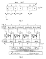
- Fig. 1 shows a known method for suppressing the sidelobe jammer.
- the signal received by the radar antenna is known to be in the time domain.
- the sum S, difference D and auxiliary channel G is supplied to a recursive clutter filter CF, which suppresses the clutter signal.
- CF recursive clutter filter
- SC sidelobe canceller
- the signals of the three channels S, D, G are transformed in a fast Fourier transformation (FFT) from the time domain into the frequency domain.
- FFT fast Fourier transformation
- signal processors with floating-point arithmetic are used to calculate an FFT, allowing a more accurate calculation of the FFT than with fixed-point processors.
- the object of the invention is to provide a method with which one opposite the prior art simpler and faster suppression of the sidelobe jammer is possible.
- the signal received by the radar antenna is first detected in the Sum, difference and auxiliary channel in a Fast Fourier transformation of the time domain transformed into the frequency domain. Subsequently, in the frequency domain the jamming signal, especially the sidelobe jammer, via sidelobe cancellation suppressed.
- the advantage here is that in the frequency domain, the processing of the signals in the sidelobe canceller easier and faster than it is in the time domain according to the prior art is possible.
- Another advantage of the invention Method is that no complicated recursive clutter filters are needed.
- FIG 3 shows, by way of example for the sum channel S n, a frequency spectrum shown in greatly simplified form in an HPRF situation with a clutter-free region M.
- the sum channel S n is shown as a uniqueness range over the sampled Doppler frequency with the pulse repetition frequency PRF.
- the area of the sidelobe clutters and the main club clutter, also referred to as Main Beam Clutter can be seen.
- the advantage here is that after the FFT the signals are in the frequency domain and thus the range of clutter signals without expensive filters, e.g. elliptical Clutter filter can be cut out.
- the radar antenna is known to receive signals in a temporal sequence.
- s k , d k and g k be the signal sequences of samples of the sum, difference and auxiliary channel in the time domain.
- FFT FFT
- N, l and P are a power of 2.
- K s (i) and K d (i) denote the scaling factors for the sum and difference channel of the sub-burst i.
- the coefficients K s and K d are stationary only for a very specific time range. Due to the repeated scanning of the radar antenna, however, the conditions for the coefficients K s and K d change . Thus, the coefficients must be constantly adapted. Such an adaptation may also be required during the FFT.
- the individual sub-bursts i with i 1... 1, where l sub-bursts give a burst, are subject to a temporal sequence (FIG. 4), as already mentioned above, whereas the samples within the sub-bursts are in the frequency domain available.
- the calculation of the scaling factors for the sub-bursts i + 1 with i 1...
- G n * (i) denotes the conjugate complex samples of the corresponding sub-channel G n (i).
- the length P 1 of this initialization phase is advantageously smaller than the length P of the individual sub-bursts i.
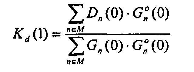
- the scaling factors K s (1) and K d (1) are calculated according to the following rule:
- the scaling factors K s (1) and K d (1) are calculated directly after switching on the receiver R x .
- the data of the initialization phase are not needed.
- the scaling factors determined in an initialization phase, l P K s, d (1) used in the first sub-burst l 1 to calculate Y n S (1) and Y n D (1).
- the subsequent method in the second sub-burst essentially corresponds to the method already described in the first sub-burst.
- the individual data Y n S, D (1) to Y n S, D (4) of the sum and difference channel calculated in the four sub-bursts are advantageously combined into a final value Y n S and Y n D for the corresponding burst.
- the individual data of the individual sub-bursts is summarized by means of appropriate twiddle factors [2].
Landscapes
- Engineering & Computer Science (AREA)
- Radar, Positioning & Navigation (AREA)
- Remote Sensing (AREA)
- Computer Networks & Wireless Communication (AREA)
- Physics & Mathematics (AREA)
- General Physics & Mathematics (AREA)
- Radar Systems Or Details Thereof (AREA)
Claims (7)
- Procédé de suppression de signaux de brouillage dans le signal de réception d'antennes radar d'applications HPRF, en particulier de systèmes radar Doppler pulsé, au moyen d'une transformation de Fourier rapide (FFT) et d'une suppression du lobe secondaire, dans lequel l'antenne radar comprend un canal de sommation (S), un canal de différence (D) et un canal auxiliaire (G), caractérisé en ce que le signal de réception est d'abord transformé dans le canal de sommation (S), le canal de différence (D) et le canal auxiliaire (G) dans une transformation de Fourier rapide (FFT) du domaine temporel au domaine fréquentiel, et ensuite, le signal de brouillage, en particulier le brouillage de lobe secondaire, est supprimé dans le domaine fréquentiel par suppression du lobe secondaire (SC).
- Procédé selon la revendication 1, caractérisé en ce qu'après la FFT, pour éliminer des signaux parasites, le domaine fréquentiel ±2Vr/λ, où Vr est la vitesse de l'application HPRF et λ est la longueur d'onde du signal de réception, est découpé du spectre de fréquences du signal de réception.
- Procédé selon l'une quelconque des revendications précédentes, caractérisé en ce que la transformation de Fourier rapide s'effectue dans une rafale comprenant N valeurs d'échantillonnage, où N = 2L et L e |N, la rafale étant divisée en ℓ sous-rafales, où ℓ = 2m et m ε{0, 1, 2, 3, 4} de longueur P.
- Procédé selon la revendication 3, caractérisé en ce que pour supprimer le brouillage de lobe secondaire au moyen d'une suppression du lobe secondaire dans les sous-rafales individuelles i, où i = 1 ... ℓ, le calcul
Yn S(i) = Sn(i) - Ks(i) * Gn(i) pour le canal de sommation (S) et
Yn D(i) = Dn(i) - Kd(i) * Gn(i) pour le canal de différence (D)
est effectué, où
Sn(i), Dn(i), Gn(i) : valeurs d'échantillonnage du canal de sommation (S), du canal de différence (D) et du canal auxiliaire (G) dans la gamme d'ondes pour la sous-rafale i,
n = 0, 1, 2, ... N-1.
Ks(i), Kd(i) : facteurs d'échelle pour la sous-rafale i+1. - Procédé selon la revendication 4, caractérisé en ce que dans une sous-rafale i, où i = 1 ... ℓ-1, les facteurs d'échelle correspondants Ks(i) et Kd(i) sont déterminés, les facteurs d'échelle calculés étant appliqués pour l'élimination du brouillage de lobe secondaire dans la sous-rafale i+1, où i = 1 ... ℓ-1, immédiatement consécutive dans le temps, et le calcul des facteurs d'échelle s'effectuant pour les sous-rafales i, où i = 1 ... ℓ-1, de la manière suivante :et
 où i = 1, ... ℓ-1,
M : domaine de signal sans parasites. - Procédé selon la revendication 5, caractérisé en ce que pour la détermination des facteurs d'échelle Ks(1) et Kd(1) de la sous-rafale i = 1, une phase d'initialisation est exécutée dont la longueur P1 est inférieure à P, et dans lequel dans la phase d'initialisation, les facteurs d'échelle Ks(1) et Kd(1) sont calculés de la manière suivante :

- Procédé selon l'une quelconque des revendications précédentes, caractérisé en ce que les i données individuelles Yn S(i) et Yn D(i), calculées dans les sous-rafales individuelles, du canal de sommation (S) et du canal de différence (D) sont regroupées en une valeur définitive Yn S et Yn D du canal de sommation (S) et du canal de différence (D) pour la rafale correspondante.
Applications Claiming Priority (2)
| Application Number | Priority Date | Filing Date | Title |
|---|---|---|---|
| DE10140498 | 2001-08-17 | ||
| DE10140498A DE10140498C1 (de) | 2001-08-17 | 2001-08-17 | Verfahren zur Unterdrückung von Jammer-Signalen |
Publications (3)
| Publication Number | Publication Date |
|---|---|
| EP1286415A2 EP1286415A2 (fr) | 2003-02-26 |
| EP1286415A3 EP1286415A3 (fr) | 2004-01-07 |
| EP1286415B1 true EP1286415B1 (fr) | 2005-08-10 |
Family
ID=7695828
Family Applications (1)
| Application Number | Title | Priority Date | Filing Date |
|---|---|---|---|
| EP02014487A Expired - Lifetime EP1286415B1 (fr) | 2001-08-17 | 2002-06-29 | Procédé de suppression de signaux de brouillage |
Country Status (3)
| Country | Link |
|---|---|
| US (1) | US6731233B2 (fr) |
| EP (1) | EP1286415B1 (fr) |
| DE (2) | DE10140498C1 (fr) |
Families Citing this family (9)
| Publication number | Priority date | Publication date | Assignee | Title |
|---|---|---|---|---|
| WO2006057583A1 (fr) * | 2004-11-26 | 2006-06-01 | Saab Ab | Rejection de lobe arriere d'antenne |
| US7492329B2 (en) | 2006-10-12 | 2009-02-17 | Hewlett-Packard Development Company, L.P. | Composite material with chirped resonant cells |
| US9674781B2 (en) | 2014-09-05 | 2017-06-06 | Google Inc. | Systems and methods for waking up devices of a fabric network |
| US9801129B2 (en) | 2014-09-05 | 2017-10-24 | Google Inc. | Systems and methods for disseminating messages among a fabric network |
| CN109655795B (zh) * | 2019-01-24 | 2020-06-30 | 南京莱斯电子设备有限公司 | 基于波形熵的米波雷达同频窄脉冲干扰抑制方法和系统 |
| CN111105509B (zh) * | 2019-12-26 | 2022-03-08 | 成都纳雷科技有限公司 | 基于毫米波雷达的etc车辆检测方法、系统及存储介质 |
| CN111948614B (zh) * | 2020-08-20 | 2023-01-10 | 电子科技大学 | 一种相控阵雷达宽带自干扰射频域分段对消系统及方法 |
| CN114428228B (zh) * | 2022-01-24 | 2024-06-07 | 西安电子科技大学 | 高重频和差天线雷达导引头的杂波抑制方法 |
| CN117784026B (zh) * | 2024-02-26 | 2024-05-03 | 中国人民解放军空军预警学院 | 一种空时频域联合主动抗复合干扰方法和装置 |
Family Cites Families (6)
| Publication number | Priority date | Publication date | Assignee | Title |
|---|---|---|---|---|
| US6268821B1 (en) * | 1977-10-21 | 2001-07-31 | Raytheon Company | Multiple band sidelobe canceller |
| US4246585A (en) * | 1979-09-07 | 1981-01-20 | The United States Of America As Represented By The Secretary Of The Air Force | Subarray pattern control and null steering for subarray antenna systems |
| US5245347A (en) * | 1980-12-29 | 1993-09-14 | Raytheon Company | All weather tactical strike system (AWTSS) and method of operation |
| FR2527785A1 (fr) * | 1982-05-27 | 1983-12-02 | Thomson Csf | Procede et dispositif de reduction de la puissance des signaux de brouillage recus par les lobes lateraux d'une antenne radar |
| US4720712A (en) * | 1985-08-12 | 1988-01-19 | Raytheon Company | Adaptive beam forming apparatus |
| US5841395A (en) * | 1997-09-12 | 1998-11-24 | Raytheon Corporation | Localized interference nulling preprocessor |
-
2001
- 2001-08-17 DE DE10140498A patent/DE10140498C1/de not_active Withdrawn - After Issue
-
2002
- 2002-06-29 EP EP02014487A patent/EP1286415B1/fr not_active Expired - Lifetime
- 2002-06-29 DE DE50203864T patent/DE50203864D1/de not_active Expired - Lifetime
- 2002-08-16 US US10/219,813 patent/US6731233B2/en not_active Expired - Fee Related
Also Published As
| Publication number | Publication date |
|---|---|
| DE50203864D1 (de) | 2005-09-15 |
| US6731233B2 (en) | 2004-05-04 |
| DE10140498C1 (de) | 2003-05-15 |
| EP1286415A3 (fr) | 2004-01-07 |
| EP1286415A2 (fr) | 2003-02-26 |
| US20040051658A1 (en) | 2004-03-18 |
Similar Documents
| Publication | Publication Date | Title |
|---|---|---|
| DE102019106529B4 (de) | Fmcw radar mit störsignalunterdrückung mittels künstlichem neuronalen netz | |
| DE102018132745B4 (de) | Fmcw radar mit störsignalunterdrückung im zeitbereich | |
| DE69713837T2 (de) | Adaptive filterung von signalangepassten daten | |
| DE102018108648B4 (de) | Fmcw radar mit störsignalunterdrückung | |
| US5539412A (en) | Radar system with adaptive clutter suppression | |
| DE60309006T2 (de) | Rauschunterdrückungsvorrichtung und -verfahren für phasengesteuerte systeme | |
| EP0795762B1 (fr) | Procédé de mise à l'échelle de l'azimut pour données SAR et processeur à grande précision pour traitement des données SCAN-SAR | |
| DE68924846T2 (de) | Radar mit anpassbarer wellenform. | |
| DE102005063417B4 (de) | Antenne für eine hochauflösende Synthetik-Apertur-Radarvorrichtung | |
| DE69906305T2 (de) | Nichtkohärente signalverarbeitung mit hohem gewinn für verbesserte detektions-schätzung | |
| DE69214257T2 (de) | Verbessertes ISAR Bilderzeugungsradarsystem | |
| DE3787015T2 (de) | Im frequenzbereich wirkendes impulsraffungsradargerät zur störechobeseitigung. | |
| EP1296157B1 (fr) | Procédé d'étalonnage des signaux radar des sous-ouvertures de l'antenne d'un système radar SAR/MTI à deux voies | |
| EP0533220A1 (fr) | Méthode pour distinguer au moins deux objectifs spécialement pour radars Doppler HPRF | |
| DE69120169T2 (de) | Beschleunigungskompensation unter Verwendung von einem Adaptivfilter | |
| DE19615353C2 (de) | Verfahren zum aufwandgünstigen Bestimmen einer Impulsantwort eines hochauflösenden bandbegrenzten Radarkanals | |
| EP1286415B1 (fr) | Procédé de suppression de signaux de brouillage | |
| DE3120490A1 (de) | Verfahren und vorrichtung zur echtzeit-radarsignalverarbeitung | |
| EP0487940B1 (fr) | Radar du type pulsdoppler | |
| DE69110646T2 (de) | Digitalkodierte Impulssignalverarbeitung. | |
| DE3301625C1 (de) | Verfahren und Vorrichtung zum Vermindern der Leistung von Störsignalen, die aus den Nebenkeulen der Antenne eines frequenzagilen Radargeräts empfangen werden | |
| DE3835343A1 (de) | Verfahren und vorrichtung zur kompensation der stoerfleckengeschwindigkeit in einem kohaerent-doppler-radar mit variabler mehrdeutiger geschwindigkeit | |
| DE3909874C2 (de) | Verfahren zur Digitalisierung und Signalverarbeitung von Empfangssignalen eines Phased-Array-Empfangssystems und Vorrichtung zum Ausführen des Verfahrens | |
| DE102004045273B4 (de) | Verfahren zur Bilderzeugung bei einem Synthetischen Apertur Radar | |
| DE4117849C2 (de) | Verfahren zur Generierung einer Referenzfunktion für eine Impulskompression von frequenz-, phasen- und/oder amplitudenmodulierten Signalen |
Legal Events
| Date | Code | Title | Description |
|---|---|---|---|
| PUAI | Public reference made under article 153(3) epc to a published international application that has entered the european phase |
Free format text: ORIGINAL CODE: 0009012 |
|
| AK | Designated contracting states |
Kind code of ref document: A2 Designated state(s): AT BE CH CY DE DK ES FI FR GB GR IE IT LI LU MC NL PT SE TR |
|
| AX | Request for extension of the european patent |
Extension state: AL LT LV MK RO SI |
|
| PUAL | Search report despatched |
Free format text: ORIGINAL CODE: 0009013 |
|
| AK | Designated contracting states |
Kind code of ref document: A3 Designated state(s): AT BE CH CY DE DK ES FI FR GB GR IE IT LI LU MC NL PT SE TR |
|
| AX | Request for extension of the european patent |
Extension state: AL LT LV MK RO SI |
|
| RIC1 | Information provided on ipc code assigned before grant |
Ipc: 7G 01S 7/285 A Ipc: 7H 01Q 3/26 B |
|
| 17P | Request for examination filed |
Effective date: 20040506 |
|
| AKX | Designation fees paid |
Designated state(s): DE FR GB SE |
|
| GRAP | Despatch of communication of intention to grant a patent |
Free format text: ORIGINAL CODE: EPIDOSNIGR1 |
|
| GRAS | Grant fee paid |
Free format text: ORIGINAL CODE: EPIDOSNIGR3 |
|
| GRAA | (expected) grant |
Free format text: ORIGINAL CODE: 0009210 |
|
| AK | Designated contracting states |
Kind code of ref document: B1 Designated state(s): DE FR GB SE |
|
| REG | Reference to a national code |
Ref country code: GB Ref legal event code: FG4D Free format text: NOT ENGLISH |
|
| REF | Corresponds to: |
Ref document number: 50203864 Country of ref document: DE Date of ref document: 20050915 Kind code of ref document: P |
|
| GBT | Gb: translation of ep patent filed (gb section 77(6)(a)/1977) |
Effective date: 20050917 |
|
| REG | Reference to a national code |
Ref country code: SE Ref legal event code: TRGR |
|
| ET | Fr: translation filed | ||
| PLBE | No opposition filed within time limit |
Free format text: ORIGINAL CODE: 0009261 |
|
| STAA | Information on the status of an ep patent application or granted ep patent |
Free format text: STATUS: NO OPPOSITION FILED WITHIN TIME LIMIT |
|
| 26N | No opposition filed |
Effective date: 20060511 |
|
| PGFP | Annual fee paid to national office [announced via postgrant information from national office to epo] |
Ref country code: SE Payment date: 20130619 Year of fee payment: 12 Ref country code: GB Payment date: 20130619 Year of fee payment: 12 Ref country code: DE Payment date: 20130620 Year of fee payment: 12 |
|
| PGFP | Annual fee paid to national office [announced via postgrant information from national office to epo] |
Ref country code: FR Payment date: 20130703 Year of fee payment: 12 |
|
| REG | Reference to a national code |
Ref country code: DE Ref legal event code: R119 Ref document number: 50203864 Country of ref document: DE |
|
| PG25 | Lapsed in a contracting state [announced via postgrant information from national office to epo] |
Ref country code: SE Free format text: LAPSE BECAUSE OF NON-PAYMENT OF DUE FEES Effective date: 20140630 |
|
| REG | Reference to a national code |
Ref country code: SE Ref legal event code: EUG |
|
| GBPC | Gb: european patent ceased through non-payment of renewal fee |
Effective date: 20140629 |
|
| REG | Reference to a national code |
Ref country code: DE Ref legal event code: R119 Ref document number: 50203864 Country of ref document: DE Effective date: 20150101 |
|
| REG | Reference to a national code |
Ref country code: FR Ref legal event code: ST Effective date: 20150227 |
|
| PG25 | Lapsed in a contracting state [announced via postgrant information from national office to epo] |
Ref country code: DE Free format text: LAPSE BECAUSE OF NON-PAYMENT OF DUE FEES Effective date: 20150101 |
|
| PG25 | Lapsed in a contracting state [announced via postgrant information from national office to epo] |
Ref country code: GB Free format text: LAPSE BECAUSE OF NON-PAYMENT OF DUE FEES Effective date: 20140629 Ref country code: FR Free format text: LAPSE BECAUSE OF NON-PAYMENT OF DUE FEES Effective date: 20140630 |