EP1286428A1 - Dispositif de verrouillage de connecteurs - Google Patents
Dispositif de verrouillage de connecteurs Download PDFInfo
- Publication number
- EP1286428A1 EP1286428A1 EP02016074A EP02016074A EP1286428A1 EP 1286428 A1 EP1286428 A1 EP 1286428A1 EP 02016074 A EP02016074 A EP 02016074A EP 02016074 A EP02016074 A EP 02016074A EP 1286428 A1 EP1286428 A1 EP 1286428A1
- Authority
- EP
- European Patent Office
- Prior art keywords
- elements
- pin
- housing
- plug
- plug connection
- Prior art date
- Legal status (The legal status is an assumption and is not a legal conclusion. Google has not performed a legal analysis and makes no representation as to the accuracy of the status listed.)
- Granted
Links
- 230000013011 mating Effects 0.000 claims description 17
- 238000003780 insertion Methods 0.000 claims description 8
- 230000037431 insertion Effects 0.000 claims description 8
- 238000006073 displacement reaction Methods 0.000 description 1
Images
Classifications
-
- H—ELECTRICITY
- H01—ELECTRIC ELEMENTS
- H01R—ELECTRICALLY-CONDUCTIVE CONNECTIONS; STRUCTURAL ASSOCIATIONS OF A PLURALITY OF MUTUALLY-INSULATED ELECTRICAL CONNECTING ELEMENTS; COUPLING DEVICES; CURRENT COLLECTORS
- H01R13/00—Details of coupling devices of the kinds covered by groups H01R12/70 or H01R24/00 - H01R33/00
- H01R13/64—Means for preventing incorrect coupling
- H01R13/641—Means for preventing incorrect coupling by indicating incorrect coupling; by indicating correct or full engagement
-
- H—ELECTRICITY
- H01—ELECTRIC ELEMENTS
- H01R—ELECTRICALLY-CONDUCTIVE CONNECTIONS; STRUCTURAL ASSOCIATIONS OF A PLURALITY OF MUTUALLY-INSULATED ELECTRICAL CONNECTING ELEMENTS; COUPLING DEVICES; CURRENT COLLECTORS
- H01R13/00—Details of coupling devices of the kinds covered by groups H01R12/70 or H01R24/00 - H01R33/00
- H01R13/64—Means for preventing incorrect coupling
- H01R13/645—Means for preventing incorrect coupling by exchangeable elements on case or base
- H01R13/6456—Means for preventing incorrect coupling by exchangeable elements on case or base comprising keying elements at different positions along the periphery of the connector
Definitions
- the invention relates to an electrical connector, consisting of a connector and a mating connector, the connector being a housing and a contact strip arranged in the housing with in the contact strip arranged contact elements and a primary and a Has secondary locking and the mating connector has a housing and in which Housing arranged contact strip with arranged in the contact strip Has contact elements.
- Plug connections of the above type are available in various designs known. These usually have a primary locking system for securing the electrical connection between the connector and the mating connector as well as a secondary lock.
- the secondary locking is used for Query whether the corresponding electrical contacts between the connector and the mating connector are completely manufactured. If so, so the secondary lock can be moved from an open to a locked one Transfer state. If a contact is not closed, it is Secondary locking cannot be converted into the locked state.
- the connector can be plugged in this state, so that Plug and mating connector make a mechanical connection, the electrical However, connection is also not by further pushing in of the plug in the mating connector.
- the object of the invention is an electrical connector to create, by means of in a simple manner, the complete established electrical connection between plug and mating connector can be checked.
- the secondary lock should not be closed the plug connection must not be able to be closed.
- the secondary lock two Functional parts comprises, the first functional part from at least two in the direction of insertion aligned pin-like elements that are vertical are movable back and forth to the direction of insertion, and with the in the second functional part aligned against the direction of insertion and firmly arranged further pin-like elements cooperate, wherein in open state of the secondary lock itself the free ends of the touch both pin-like elements and in the locked state of the Secondary locking are arranged side by side.
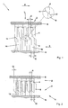
- a secondary lock 1 which consists of a first functional part 2, which is not shown in the drawings illustrated connector and a further functional part 3, which one in mating connector not shown in the drawings.
- the first functional part 2 has pin-like elements 4, which are next to each other are arranged at a defined distance 5 on a carrier 6.
- the elements 4 extend in the direction of insertion (arrow 7) and are parallel aligned with each other.
- there is a spatial one Arrangement of the elements 4 conceivable.
- the carrier 6 is together with the elements 4 can be moved back and forth perpendicular to the direction of insertion (arrow 8).
- the further functional part 3 is in a mating connector, preferably one Male header, fixed arrangement.
- the pin-like elements 9 extend against the direction of insertion (arrow 7) and are also in a defined distance 10 aligned parallel to each other.
- the elements 4, 9 exist together with the carrier 6 for the Elements 4 made of plastic.
- the connector is placed on the mating connector, whereby the secondary locking 1, as shown in Fig. 1, in the position is "open".
- the plug can be plugged in as far as the mating connector Push the direction of insertion (arrow 7) until the free ends of the elements 4 of the first functional part 2 of the secondary locking the free ends of the Touch elements 9 of the second functional part 3.
- the free ends of the elements 4, 9 preferably have oblique shapes Surfaces 11, 12. Because of this training, the first functional part 2 are displaced in the direction of the arrow by a displacement path 13, see above that the elements 4 are arranged over an intermediate space 14.
- This Gap 14 has a width that is at least the width of the elements 4 corresponds. In this position the plug can be in its end position be transferred. The elements 4 slide into the space 14 until the end position shown in FIG. 2 is reached.
Landscapes
- Details Of Connecting Devices For Male And Female Coupling (AREA)
- Coupling Device And Connection With Printed Circuit (AREA)
Applications Claiming Priority (2)
| Application Number | Priority Date | Filing Date | Title |
|---|---|---|---|
| DE20113203U DE20113203U1 (de) | 2001-08-09 | 2001-08-09 | Elektrischer Steckverbinder mit integrierter Sekundärverriegelung |
| DE20113203U | 2001-08-09 |
Publications (2)
| Publication Number | Publication Date |
|---|---|
| EP1286428A1 true EP1286428A1 (fr) | 2003-02-26 |
| EP1286428B1 EP1286428B1 (fr) | 2005-01-05 |
Family
ID=7960342
Family Applications (1)
| Application Number | Title | Priority Date | Filing Date |
|---|---|---|---|
| EP02016074A Expired - Lifetime EP1286428B1 (fr) | 2001-08-09 | 2002-07-19 | Dispositif de verrouillage de connecteurs |
Country Status (4)
| Country | Link |
|---|---|
| US (1) | US20030040209A1 (fr) |
| EP (1) | EP1286428B1 (fr) |
| JP (1) | JP3091935U (fr) |
| DE (2) | DE20113203U1 (fr) |
Families Citing this family (1)
| Publication number | Priority date | Publication date | Assignee | Title |
|---|---|---|---|---|
| JP5798934B2 (ja) * | 2012-01-17 | 2015-10-21 | 矢崎総業株式会社 | 電気コネクタ |
Citations (4)
| Publication number | Priority date | Publication date | Assignee | Title |
|---|---|---|---|---|
| US5244400A (en) * | 1990-10-22 | 1993-09-14 | Yazaki Corporation | Electrical connector with fastening cam member |
| DE29906583U1 (de) * | 1999-04-14 | 1999-07-15 | Weidmüller Interface GmbH & Co., 32758 Detmold | Kodiervorrichtung zur Kodierung eines elektrischen Gerätes |
| EP1032087A1 (fr) * | 1998-09-11 | 2000-08-30 | Hosiden Corporation | Connecteur male et femelle, et ensemble connecteur |
| DE20019792U1 (de) * | 2000-11-21 | 2001-02-15 | Schmitt, Fred R., 74388 Talheim | Steckverbinder-Gehäuse mit Kodiereinrichtung |
Family Cites Families (1)
| Publication number | Priority date | Publication date | Assignee | Title |
|---|---|---|---|---|
| KR100413026B1 (ko) * | 1998-04-30 | 2004-03-22 | 삼성전자주식회사 | 커넥터어셈블리 |
-
2001
- 2001-08-09 DE DE20113203U patent/DE20113203U1/de not_active Expired - Lifetime
-
2002
- 2002-07-19 DE DE50201940T patent/DE50201940D1/de not_active Expired - Lifetime
- 2002-07-19 EP EP02016074A patent/EP1286428B1/fr not_active Expired - Lifetime
- 2002-08-06 JP JP2002004913U patent/JP3091935U/ja not_active Expired - Lifetime
- 2002-08-09 US US10/216,142 patent/US20030040209A1/en not_active Abandoned
Patent Citations (4)
| Publication number | Priority date | Publication date | Assignee | Title |
|---|---|---|---|---|
| US5244400A (en) * | 1990-10-22 | 1993-09-14 | Yazaki Corporation | Electrical connector with fastening cam member |
| EP1032087A1 (fr) * | 1998-09-11 | 2000-08-30 | Hosiden Corporation | Connecteur male et femelle, et ensemble connecteur |
| DE29906583U1 (de) * | 1999-04-14 | 1999-07-15 | Weidmüller Interface GmbH & Co., 32758 Detmold | Kodiervorrichtung zur Kodierung eines elektrischen Gerätes |
| DE20019792U1 (de) * | 2000-11-21 | 2001-02-15 | Schmitt, Fred R., 74388 Talheim | Steckverbinder-Gehäuse mit Kodiereinrichtung |
Also Published As
| Publication number | Publication date |
|---|---|
| JP3091935U (ja) | 2003-02-21 |
| US20030040209A1 (en) | 2003-02-27 |
| EP1286428B1 (fr) | 2005-01-05 |
| DE50201940D1 (de) | 2005-02-10 |
| DE20113203U1 (de) | 2002-12-19 |
Similar Documents
| Publication | Publication Date | Title |
|---|---|---|
| EP1841016B1 (fr) | Connecteur à fiches métallique | |
| DE19813458B4 (de) | Elektrischer Verbinder | |
| DE112012003574T5 (de) | Buchse und ein die Buchse verwendender Verbinder | |
| DE3906667A1 (de) | Steckverbinder mit sperrmechanismus | |
| DE10203162A1 (de) | Verbinder | |
| DE69409015T2 (de) | Steckverbinder mit Verriegelungshebel | |
| DE4138465A1 (de) | Verbinder mit doppelverriegelung | |
| DE69013734T2 (de) | Elektrischer Verbinder. | |
| DE69310439T2 (de) | Verriegelbarer elektrischer Verbinderanordnung | |
| DE202022101364U1 (de) | Steckverbinder, Halteelement sowie Set aus einem Steckverbinder und einem Halteelement | |
| EP3403298B1 (fr) | Connecteur enfichable | |
| DE60100099T2 (de) | Entriegelungsmechanismus | |
| DE10012324A1 (de) | Steckverbindersystem | |
| DE10204842B4 (de) | Leiterplattensteckverbinder | |
| EP1538713B1 (fr) | Dispositif de connexion avec saillie d'arrêt et encoche | |
| DE2213747A1 (de) | Elektrische Steckverbindung | |
| EP1286428A1 (fr) | Dispositif de verrouillage de connecteurs | |
| DE4100649A1 (de) | Elektrische steckverbindung | |
| DE102020109539A1 (de) | Stecker zur Herstellung einer Steckverbindung mit einem Gegenstecker und Steckverbindung mit einem solchen Stecker | |
| DE19814401B4 (de) | Elektrischer Kontakt zur Kontaktierung eines zylindrischen komplementären Kontaktstiftes und entsprechende elektrische Steckverbinder | |
| DE19747115A1 (de) | Elektrische Steckverbinderanordnung und elektrischer Kontakt | |
| EP2262062B1 (fr) | Connecteur à fiches | |
| DE20104184U1 (de) | Elektrisches Kontaktelement | |
| DE4242878B4 (de) | Buchsenkontakt für eine elektrische Steckverbindung | |
| DE102023132529A1 (de) | Steckverbinder und Anordnung aus einer Leiterplatte und einem Steckverbinder |
Legal Events
| Date | Code | Title | Description |
|---|---|---|---|
| PUAI | Public reference made under article 153(3) epc to a published international application that has entered the european phase |
Free format text: ORIGINAL CODE: 0009012 |
|
| AK | Designated contracting states |
Kind code of ref document: A1 Designated state(s): AT BE BG CH CY CZ DE DK EE ES FI FR GB GR IE IT LI LU MC NL PT SE SK TR |
|
| AX | Request for extension of the european patent |
Extension state: AL LT LV MK RO SI |
|
| 17P | Request for examination filed |
Effective date: 20030826 |
|
| AKX | Designation fees paid |
Designated state(s): DE FR GB IT SE |
|
| 17Q | First examination report despatched |
Effective date: 20031216 |
|
| GRAP | Despatch of communication of intention to grant a patent |
Free format text: ORIGINAL CODE: EPIDOSNIGR1 |
|
| GRAS | Grant fee paid |
Free format text: ORIGINAL CODE: EPIDOSNIGR3 |
|
| GRAA | (expected) grant |
Free format text: ORIGINAL CODE: 0009210 |
|
| AK | Designated contracting states |
Kind code of ref document: B1 Designated state(s): DE FR GB IT SE |
|
| REG | Reference to a national code |
Ref country code: GB Ref legal event code: FG4D Free format text: NOT ENGLISH |
|
| REG | Reference to a national code |
Ref country code: IE Ref legal event code: FG4D Free format text: GERMAN |
|
| REF | Corresponds to: |
Ref document number: 50201940 Country of ref document: DE Date of ref document: 20050210 Kind code of ref document: P |
|
| REG | Reference to a national code |
Ref country code: SE Ref legal event code: TRGR |
|
| GBT | Gb: translation of ep patent filed (gb section 77(6)(a)/1977) |
Effective date: 20050322 |
|
| PLBE | No opposition filed within time limit |
Free format text: ORIGINAL CODE: 0009261 |
|
| STAA | Information on the status of an ep patent application or granted ep patent |
Free format text: STATUS: NO OPPOSITION FILED WITHIN TIME LIMIT |
|
| 26N | No opposition filed |
Effective date: 20051006 |
|
| ET | Fr: translation filed | ||
| REG | Reference to a national code |
Ref country code: GB Ref legal event code: FG4D Free format text: NOT ENGLISH |
|
| PGFP | Annual fee paid to national office [announced via postgrant information from national office to epo] |
Ref country code: DE Payment date: 20100924 Year of fee payment: 9 |
|
| PGFP | Annual fee paid to national office [announced via postgrant information from national office to epo] |
Ref country code: FR Payment date: 20110729 Year of fee payment: 10 |
|
| PGFP | Annual fee paid to national office [announced via postgrant information from national office to epo] |
Ref country code: SE Payment date: 20110721 Year of fee payment: 10 Ref country code: GB Payment date: 20110721 Year of fee payment: 10 |
|
| PGFP | Annual fee paid to national office [announced via postgrant information from national office to epo] |
Ref country code: IT Payment date: 20110728 Year of fee payment: 10 |
|
| REG | Reference to a national code |
Ref country code: SE Ref legal event code: EUG |
|
| GBPC | Gb: european patent ceased through non-payment of renewal fee |
Effective date: 20120719 |
|
| REG | Reference to a national code |
Ref country code: FR Ref legal event code: ST Effective date: 20130329 |
|
| PG25 | Lapsed in a contracting state [announced via postgrant information from national office to epo] |
Ref country code: DE Free format text: LAPSE BECAUSE OF NON-PAYMENT OF DUE FEES Effective date: 20130201 Ref country code: SE Free format text: LAPSE BECAUSE OF NON-PAYMENT OF DUE FEES Effective date: 20120720 Ref country code: FR Free format text: LAPSE BECAUSE OF NON-PAYMENT OF DUE FEES Effective date: 20120731 Ref country code: GB Free format text: LAPSE BECAUSE OF NON-PAYMENT OF DUE FEES Effective date: 20120719 |
|
| PG25 | Lapsed in a contracting state [announced via postgrant information from national office to epo] |
Ref country code: IT Free format text: LAPSE BECAUSE OF NON-PAYMENT OF DUE FEES Effective date: 20120719 |
|
| REG | Reference to a national code |
Ref country code: DE Ref legal event code: R119 Ref document number: 50201940 Country of ref document: DE Effective date: 20130201 |