EP1286473B1 - Procédé pour supprimer des impulsions parasites lors de la réception radio - Google Patents
Procédé pour supprimer des impulsions parasites lors de la réception radio Download PDFInfo
- Publication number
- EP1286473B1 EP1286473B1 EP02017550A EP02017550A EP1286473B1 EP 1286473 B1 EP1286473 B1 EP 1286473B1 EP 02017550 A EP02017550 A EP 02017550A EP 02017550 A EP02017550 A EP 02017550A EP 1286473 B1 EP1286473 B1 EP 1286473B1
- Authority
- EP
- European Patent Office
- Prior art keywords
- signal
- stereo
- digital
- input
- output
- Prior art date
- Legal status (The legal status is an assumption and is not a legal conclusion. Google has not performed a legal analysis and makes no representation as to the accuracy of the status listed.)
- Expired - Lifetime
Links
- 230000001629 suppression Effects 0.000 title claims description 4
- 230000005236 sound signal Effects 0.000 claims abstract description 19
- 238000000034 method Methods 0.000 claims description 34
- 239000011159 matrix material Substances 0.000 claims description 33
- 230000015654 memory Effects 0.000 claims description 23
- 238000012935 Averaging Methods 0.000 claims 2
- 230000003595 spectral effect Effects 0.000 description 2
- 238000011410 subtraction method Methods 0.000 description 2
- 238000012876 topography Methods 0.000 description 2
- 230000006870 function Effects 0.000 description 1
- 230000001771 impaired effect Effects 0.000 description 1
- 230000001902 propagating effect Effects 0.000 description 1
- 238000005070 sampling Methods 0.000 description 1
- 238000000926 separation method Methods 0.000 description 1
- 230000002123 temporal effect Effects 0.000 description 1
Images



Classifications
-
- H—ELECTRICITY
- H04—ELECTRIC COMMUNICATION TECHNIQUE
- H04B—TRANSMISSION
- H04B1/00—Details of transmission systems, not covered by a single one of groups H04B3/00 - H04B13/00; Details of transmission systems not characterised by the medium used for transmission
- H04B1/06—Receivers
- H04B1/10—Means associated with receiver for limiting or suppressing noise or interference
- H04B1/1027—Means associated with receiver for limiting or suppressing noise or interference assessing signal quality or detecting noise/interference for the received signal
-
- H—ELECTRICITY
- H04—ELECTRIC COMMUNICATION TECHNIQUE
- H04H—BROADCAST COMMUNICATION
- H04H40/00—Arrangements specially adapted for receiving broadcast information
- H04H40/18—Arrangements characterised by circuits or components specially adapted for receiving
- H04H40/27—Arrangements characterised by circuits or components specially adapted for receiving specially adapted for broadcast systems covered by groups H04H20/53 - H04H20/95
- H04H40/36—Arrangements characterised by circuits or components specially adapted for receiving specially adapted for broadcast systems covered by groups H04H20/53 - H04H20/95 specially adapted for stereophonic broadcast receiving
- H04H40/45—Arrangements characterised by circuits or components specially adapted for receiving specially adapted for broadcast systems covered by groups H04H20/53 - H04H20/95 specially adapted for stereophonic broadcast receiving for FM stereophonic broadcast systems receiving
- H04H40/72—Arrangements characterised by circuits or components specially adapted for receiving specially adapted for broadcast systems covered by groups H04H20/53 - H04H20/95 specially adapted for stereophonic broadcast receiving for FM stereophonic broadcast systems receiving for noise suppression
Definitions
- the invention relates to a method for suppressing interference in the received signal of a stereo radio receiver, in which from the analog stereo multiplex signal in a stereo decoder the digital (LR) signal and the digital (L + R) signal and in a stereo matrix the digital L signal and the digital R signal is generated.
- the invention further relates to a Sterorund garmpftuler with a receiving unit for generating the analog stereo multiplex signal, with a stereo decoder for generating the digital (LR) signal and the digital (L + R) signal from the analog stereo multiplex signal and a stereo matrix for generating the digital L.
- Signal and the digital R signal from the (LR) signal and the (L + R) signal are also known as Sterorund Sterorund Sterorund Ster with a receiving unit for generating the analog stereo multiplex signal, with a stereo decoder for generating the digital (LR) signal and the digital (L + R) signal from the analog stereo multiplex signal and a stereo matrix for generating the digital L.
- Signal and the digital R signal from the (LR) signal and the (L + R) signal are examples of the digital L.
- FM broadcasters transmit the so-called stereo multiplex signal, which is formed from the audio signal signal - also called mono signal - with a frequency of up to 15 kHz, the stereo pilot tone with a frequency of 19 kHz and the stereo signal with a frequency of 23 kHz to 53 kHz.
- the analog stereo multiplex signal is obtained in a receiving unit from the received signal and digitized by means of an analog-to-digital converter.
- the stereo digital multiplexed signal is processed in a stereo decoder that generates the (L-R) signal and the (L + R) signal from the stereo digital multiplexed signal.
- a stereo-matrix computes the left-channel audio signal (the so-called L signal) and the right-channel audio signal as R, by forming the sum and difference signals from the (LR) signal and the (L + R) signal Signal is called.
- Noise suppression at the level of the stereo multiplex signal is particularly effective in suppressing interference caused by multipath reception, because it prevents interference from propagating to the audio level.
- the noise blanking has the disadvantage that gaps are caused in the received signal.
- Switching from stereo to monaural playback is particularly useful when the reception field strength is reduced, that is, when noise increases, to improve reception quality.
- the disadvantage of switching from stereo to mono playback is that it does without a stereophonic sound.
- the US 5,303,414 describes a method in which, in the event of a fault, the demodulated audio signal is replaced by its last valid value. For this purpose a sample and hold circuit is used.
- the EP 0 208 082 A2 describes a radio receiving apparatus in which the samples of the digital audio signal are suppressed in the event of a fault and replaced by interpolated values.
- the inventive method provides to generate a digital field strength signal in the stereo broadcast receiver according to the invention, which represents the analog field strength signal.
- This digital field strength signal can be generated for example by digitizing the analog field strength signal. It can, for. B. but also be derived from a digital IF signal of the IF stage of the stereo radio receiver.
- a third alternative is to derive the digital field strength signal from the stereo multiplex signal.
- the stereo multiplex signal can be analyzed, for example, according to the spectral subtraction method. The minimum of the power density of the disturbed stereo multiplex signal is determined. From the minimum of power density, which is the analog Field strength signal represents, the digital field strength signal is derived.
- the spectral subtraction method and the determination of the minimum of the power density are in DE 44 45 983 C2 described and explained.
- the method according to the invention now provides for checking whether the digital field strength signal lies within or outside a predefinable tolerance range.
- the inventive method further provides to generate the samples of the digital audio signal by interpolation at least as long as the digital field strength signal is outside the predetermined tolerance range.
- the tolerance range follows the temporal changes of the reception field strength.
- the digital audio signal is buffered in at least one intermediate memory.
- the (L-R) signal and the (L + R) signal are latched in each case in a latch located between the stereo decoder and the stereo matrix of the stereo radio receiver.
- a further exemplary embodiment provides for the L signal and the R signal to be buffered in each case in a buffer store behind the stereo matrix.
- both the samples of the L signal and the R signal are to be interpolated.
- a further exemplary embodiment of the invention provides for replacing not only the samples of the audio signal lying within the tolerance range by interpolated samples, but also for replacing a predeterminable number of sample values before and / or after the interpolation interval with interpolated samples.
- This measure is characterized by the advantage that the incoming and outgoing vibrations are taken into account in the interpolation, whereby the sound is improved. In addition, these measures compensate for inaccuracies in the triggering time.
- a further embodiment of the invention is provided with a trigger generator which generates a trigger signal for marking the disturbed samples of the audio signal to be replaced by interpolated samples when the digital field strength signal is outside the tolerance range.
- the duration of the trigger signal therefore determines the length of the interpolation interval.
- the interpolation is performed with Lagrangian polynomials.
- N + 1) / 2 samples are provided as nodes before and after the interpolation interval.
- values of 10 to 20 and for N of 1 to 3 are particularly well suited.
- the stereo receiver can be switched from stereo to monaural at least during the interpolation interval. In this case, only the samples of the mono signal are to be interpolated. In order to fade inward and outward swinging processes largely in the sound picture, as in the case of interpolation, it makes sense to switch the stereo radio receiver from stereo playback to mono playback already before the interpolation interval for a predefinable period of time. Analogous to this measure, at the end of the interpolation interval, there is no immediate monaural playback Stereo playback switched; rather, the switching back to stereo playback takes place with a predefinable time delay.
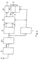
- FIG. 1 a section of a first embodiment of the stereo broadcast receiver according to the invention is shown, comprising the receiving unit, the stereo decoder and the stereo matrix of the stereo radio receiver.
- the reception signal is at the antenna input A of the receiving unit E.
- the output of the receiving unit E, at which the stereo multiplex signal MPX obtained in the receiving unit E is removable, is connected to the input of a first analog-to-digital converter W1, while the output of the receiving unit E, at which the analog field strength signal AF can be tapped, is connected to the input of a second analog-to-digital converter W2.
- the output of the first analog-to-digital converter W1 is connected to the input of the stereo decoder D, whose first output, to which the (LR) signal can be picked up, is connected to the input of a first buffer S1, while the second output of the stereo decoder D, at which the (L + R) signal is detachably connected to the input of a second latch S2.
- the output of the first latch S1 and the second latch S2 is connected to one input of the stereo matrix M, at one of whose output the L signal and at the other output the R signal is removable.
- the output of the second analog-to-digital converter W2 is connected to the input of a trigger generator T, the output of which is connected to the control input of the stereo matrix M and to an interpolation unit I connected to the second buffer S2.
- the analog stereo multiplex signal MPX is obtained from the received signal located at the antenna input A, which is digitized by means of the analog-to-digital converter W1.
- the stereo decoder D generates from the digital stereo multiplex signal supplied by the analog-to-digital converter W1 the digital (LR) signal, which is latched in the latch (S1), and the (L + R) signal, which is latched in the latch S2.
- the analog-to-digital converter W2 digitizes the analog field strength signal AF received by the receiving unit (E).
- the digital field strength signal DF generated by the analog-to-digital converter W2 controls the trigger generator T, which sends a trigger signal to the control input of the stereo matrix M and the interpolation unit I connected to the latch S2 when the digital field strength signal DF is outside the predefinable tolerance range.
- the interpolation unit I replaces the samples of the (L + R) signal with interpolated samples.
- Stereomatrix M will be from the samples of the (LR) signal supplied by the latch S1 and the samples of the (L + R) signal supplied by the buffer S2, the samples of the L signal and the R signal are calculated by summation and difference. These two signals - the L signal and the R signal - are picked up at the two outputs of the stereo matrix M.
- the output of the first analog-to-digital converter W1 is connected not only to the input of the stereo decoder D but also to the input of the trigger generator T, while the second analog-to-digital converter is omitted.
- the digital stereo multiplex signal serves as a digital field strength signal because it represents the analog field strength signal.
- the function of the second embodiment corresponds to that of the first embodiment.
- the illustrated third embodiment differs from the first in that the two latches S1 and S2 and the interpolation unit I are no longer arranged between the stereo decoder D and the stereo matrix M, but according to the stereo matrix M.
- the buffer S1 therefore, the samples of the L signal are latched, while in the buffer S2, the samples of the R signal are latched.
- the interpolation unit I replaces the samples of the L signal and the R signal with interpolated samples.
- FIG. 4 illustrated fourth embodiment differs from the third in that the output of the first analog-to-digital converter W1 is also connected to the input of the trigger generator T.
- the second analog-digital converter W2 is omitted, because it is no longer necessary because the digitized stereo multiplex signal serves as a digital field strength signal DF.
- the method according to the invention is generally suitable for suppressing interference in the received signal of a stereo radio receiver. But in particular can be with the method according to the invention pulse-like disorders, as z. B. caused by the ignition of a motor vehicle, effectively suppress.
- An essential advantage of the method according to the invention and of the stereo radio receiver according to the invention is that the switching from stereo reproduction to mono reproduction only takes place with substantially greater interference in the received signal than in the known methods and stereo radio receivers.
Landscapes
- Engineering & Computer Science (AREA)
- Signal Processing (AREA)
- Computer Networks & Wireless Communication (AREA)
- Noise Elimination (AREA)
- Stereo-Broadcasting Methods (AREA)
Claims (36)
- Procédé pour la suppression de perturbations dans le signal de réception d'un récepteur de radiodiffusion stéréo, procédé dans lequel un signal numérique L-R et un signal numérique L+R sont générés à partir d'un signal multiplex stéréo analogique (MPX) dans un décodeur stéréo (D) et un signal numérique L et un signal numérique R sont générés dans une matrice stéréo (M), un signal d'intensité de champ numérique (DF) représentant un signal d'intensité de champ analogique (AF) est généré et les valeurs de balayage du signal audio numérique sont générées par interpolation à partir des valeurs de balayage du signal audio numérique mémorisées au préalable au moins aussi longtemps que le signal d'intensité de champ numérique (DF) se trouve à l'extérieur d'une plage de tolérance pré-définissable, caractérisé en ce qu'une intensité de champ moyenne, à l'aide de laquelle la position de la plage de tolérance est définie, est déterminée par un calcul de la moyenne dans le temps du signal d'intensité de champ analogique ou numérique (AF, DF).
- Procédé selon la revendication 1, caractérisé en ce que le signal d'intensité de champ numérique (DF) est généré par la numérisation du signal d'intensité de champ analogique (AF).
- Procédé selon la revendication 1, caractérisé en ce que le signal d'intensité de champ numérique (DF) est généré à partir d'un signal numérique ZF de l'étage ZF du récepteur de radiodiffusion stéréo.
- Procédé selon la revendication 1, caractérisé en ce que le signal d'intensité de champ numérique (DF) est dérivé du signal multiplex stéréo (MPX).
- Procédé selon l'une quelconque des revendications 1 à 4, caractérisé en ce que le signal audio numérique est mémorisé temporairement dans au moins une mémoire temporaire (S1, S2).
- Procédé selon la revendication 5, caractérisé en ce que le signal L-R et le signal L+R sont mémorisés temporairement chacun dans une mémoire temporaire (S1, S2) se trouvant entre le décodeur stéréo (D) et la matrice stéréo (M) ou le signal L et le signal R sont mémorisés temporairement chacun dans une mémoire temporaire (S1, S2) se trouvant derrière la matrice stéréo (M).
- Procédé selon l'une quelconque des revendications 1 à 6, caractérisé en ce qu'un nombre prédéterminable de valeurs de balayage du signal audio se trouvant avant et/ou après l'intervalle d'interpolation déterminé par la plage de tolérance sont également remplacées par des valeurs de balayage interpolées.
- Procédé selon l'une quelconque des revendications 1 à 7, caractérisé en ce qu'un générateur de déclenchement (T) génère un signal de déclenchement pour le marquage des valeurs de balayage du signal audio brouillées devant être remplacées par des valeurs de balayage interpolées lorsque le signal d'intensité de champ numérique (DF) se trouve à l'extérieur de la plage de tolérance.
- Procédé selon l'une quelconque des revendications 1 à 8, caractérisé en ce que la durée du signal de déclenchement détermine la longueur de l'intervalle d'interpolation.
- Procédé selon l'une quelconque des revendications 1 à 9, caractérisé en ce que l'interpolation est réalisée avec des polynômes de Lagrange.
- Procédé selon la revendication 10, caractérisé en ce que (N+1)/2 valeurs de balayage sont prévues comme points avant et après l'intervalle d'interpolation lors de l'interpolation de M-valeurs de balayage avec un polynôme du N-ième degré.
- Procédé selon l'une quelconque des revendications 1 à 11, caractérisé en ce que le signal L-R et le signal L+R sont mémorisés temporairement et en ce que le signal L+R et/ou le signal L-R sont interpolés.
- Procédé selon l'une quelconque des revendications 1 à 11, caractérisé en ce que le signal L et le signal R sont mémorisés et interpolés.
- Procédé selon l'une quelconque des revendications 1 à 11, caractérisé en ce que le récepteur stéréo est commuté entre une reproduction stéréo et une reproduction mono au moins pendant la durée de l'intervalle d'interpolation.
- Procédé selon la revendication 14, caractérisé en ce que le récepteur stéréo est également commuté sur une reproduction mono pendant un intervalle de temps pré-définissable se trouvant avant ou après l'intervalle d'interpolation.
- Procédé selon la revendication 14 ou 15, caractérisé en ce que la commutation entre la reproduction mono et la reproduction stéréo est réalisée avec une temporisation.
- Récepteur de radiodiffusion stéréo avec- une unité de réception (E) pour la génération d'un signal multiplex stéréo analogique (MPX), avec- un décodeur stéréo (D) pour la génération d'un signal numérique L-R et du signal numérique L+R à partir du signal multiplex stéréo analogique (MPX), avec- une matrice stéréo (M) pour la génération d'un signal numérique L et d'un signal numérique R à partir du signal numérique L-R et du signal numérique L+R, avec- des moyens pour la génération d'un signal d'intensité de champ numérique (DF) représentant un signal d'intensité de champ analogique (AF) de telle sorte que les valeurs de balayage du signal audio numérique peuvent être générées par interpolation au moins aussi longtemps que le signal d'intensité de champ numérique (DF) se trouve à l'extérieur d'une plage de tolérance pré-définissable,caractérisé en ce que la position de la plage de tolérance est définie par une intensité de champ moyenne déterminée par un calcul de la moyenne dans le temps du signal d'intensité de champ analogique ou numérique (AF, DF).
- Récepteur de radiodiffusion stéréo selon la revendication 17, qui comporte en outre un convertisseur analogique-numérique pour la génération du signal d'intensité de champ numérique (DF) par la numérisation du signal d'intensité de champ analogique (AF).
- Récepteur de radiodiffusion stéréo selon la revendication 17, dans lequel il est prévu une génération du signal d'intensité de champ numérique (DF) à partir d'un signal numérique ZF de l'étage ZF du récepteur de radiodiffusion stéréo.
- Récepteur de radiodiffusion stéréo selon la revendication 17, dans lequel il est prévu une génération du signal d'intensité de champ numérique (DF) à partir du signal multiplex stéréo (MPX).
- Récepteur de radiodiffusion stéréo selon l'une quelconque des revendications 17 à 20, dans lequel il est prévu une mémorisation temporaire du signal audio numérique dans au moins une mémoire temporaire (S1, S2).
- Récepteur de radiodiffusion stéréo selon la revendication 21, dans lequel il est prévu une mémorisation temporaire du signal L-R et du signal L+R chacun dans une mémoire temporaire (S1, S2) respective se trouvant entre le décodeur stéréo (D) et la matrice stéréo (M) ou une mémorisation temporaire du signal L et du signal R chacun dans une mémoire temporaire (S1, S2) respective se trouvant derrière la matrice stéréo (M).
- Récepteur de radiodiffusion stéréo selon l'une quelconque des revendications 17 à 22, dans lequel il est prévu de remplacer un nombre de valeurs de balayage du signal audio se trouvant avant et/ou après l'intervalle d'interpolation déterminé par la plage de tolérance par des valeurs de balayage interpolées.
- Récepteur de radiodiffusion stéréo selon l'une quelconque des revendications 17 à 23, caractérisé en ce qu'il est prévu un générateur de déclenchement (D) pour la génération d'un signal de déclenchement qui est prévu pour le marquage des valeurs de balayage du signal audio devant être remplacées par des valeurs de balayage interpolées lorsque le signal d'intensité de champ numérique (DF) se trouve à l'extérieur de la plage de tolérance.
- Récepteur de radiodiffusion stéréo selon l'une quelconque des revendications 17 à 24, dans lequel il est prévu que la durée du signal de déclenchement détermine la longueur de l'intervalle d'interpolation.
- Récepteur de radiodiffusion stéréo selon l'une quelconque des revendications 17 à 25, dans lequel l'interpolation est réalisée avec des polynômes de Lagrange.
- Récepteur de radiodiffusion stéréo selon la revendication 26, caractérisé en ce que (N+1)/2 valeurs de balayage sont prévues comme points avant et après l'intervalle d'interpolation lors de l'interpolation de M-valeurs de balayage avec un polynôme du N-ième degré.
- Récepteur de radiodiffusion stéréo selon l'une quelconque des revendications 17 à 27, dans lequel il est prévu une mémorisation temporaire du signal L-R et du signal L+R et une interpolation du signal L+R et/ou du signal L-R.
- Récepteur de radiodiffusion stéréo selon l'une quelconque des revendications 17 à 27, dans lequel il est prévu une mémorisation temporaire et une interpolation du signal L et du signal R.
- Récepteur de radiodiffusion stéréo selon l'une quelconque des revendications 17 à 27, dans lequel il est prévu une commutation du récepteur stéréo entre une reproduction stéréo et une reproduction mono au moins pendant la durée de l'intervalle d'interpolation.
- Récepteur de radiodiffusion stéréo selon la revendication 30, dans lequel il est prévu une commutation du récepteur stéréo sur une reproduction mono pendant un intervalle de temps pré-définissable avant et/ou après l'intervalle d'interpolation.
- Récepteur de radiodiffusion stéréo selon la revendication 30 ou 31, caractérisé en ce que la commutation entre la reproduction mono et la reproduction stéréo est prévue avec une temporisation.
- Récepteur de radiodiffusion stéréo selon l'une quelconque des revendications 17 à 28 ou 30 à 32, caractérisé en ce que le signal de réception se trouve à l'entrée d'antenne (A) d'une unité de réception (E) dont la première sortie, au niveau de laquelle le signal multiplex stéréo analogique (MPX) peut être prélevé, est raccordée à l'entrée d'un premier convertisseur analogique-numérique (W1) et dont la seconde sortie, au niveau de laquelle le signal analogique d'intensité de champ (AF) peut être prélevé, est raccordée à l'entrée d'un second convertisseur analogique-numérique (W2), en ce que la sortie du premier convertisseur analogique-numérique (W1) est raccordée à l'entrée du décodeur stéréo (D) dont la première sortie, au niveau de laquelle le signal L-R peut être prélevé, est raccordée à l'entrée d'une première mémoire temporaire (S1) alors que sa seconde sortie, au niveau de laquelle le signal L+R peut être prélevé, est raccordée à l'entrée d'une seconde mémoire temporaire (S2), en ce que les sorties des première et seconde mémoires temporaires (S1, S2) sont raccordées aux deux entrées audio de la matrice stéréo (M) au niveau des sorties de laquelle le signal L et le signal R peuvent être prélevés, en ce que la sortie du second convertisseur analogique-numérique (W2) est raccordée à l'entrée d'un générateur de déclenchement (T) et en ce que la sortie du générateur de déclenchement (T) est raccordée à l'entrée de commande de la matrice stéréo (M) et à une unité d'interpolation (I) raccordée à la seconde mémoire temporaire (S2).
- Récepteur de radiodiffusion stéréo selon l'une quelconque des revendications 17 à 28 ou 30 à 32, caractérisé en ce que le signal de réception se trouve à l'entrée d'antenne (A) d'une unité de réception (E) dont la sortie, au niveau de laquelle le signal multiplex stéréo analogique (MPX) peut être prélevé, est raccordée à l'entrée d'un convertisseur analogique-numérique (W1) dont la sortie est raccordée à l'entrée d'un générateur de déclenchement (T) et à l'entrée du décodeur stéréo (D) dont la première sortie, au niveau de laquelle le signal L-R peut être prélevé, est raccordée à l'entrée d'une première mémoire temporaire (S1) alors que sa seconde sortie, au niveau de laquelle le signal L+R peut être prélevé, est raccordée à l'entrée d'une seconde mémoire temporaire (S2), en ce que les sorties des première et seconde mémoires temporaires (S1, S2) sont raccordées aux deux entrées audio de la matrice stéréo (M) au niveau des sorties de laquelle le signal L et le signal R peuvent être prélevés, et en ce que la sortie du générateur de déclenchement (T) est raccordée à l'entrée de commande de la matrice stéréo (M) et à une unité d'interpolation (I) raccordée à la seconde mémoire temporaire (S2).
- Récepteur de radiodiffusion stéréo selon l'une quelconque des revendications 17 à 27 ou 29 à 32, caractérisé en ce que le signal de réception se trouve à l'entrée d'antenne (A) d'une unité de réception (E) dont la première sortie, au niveau de laquelle le signal multiplex stéréo analogique (MPX) peut être prélevé, est raccordée à l'entrée d'un premier convertisseur analogique-numérique (W1) et dont la seconde sortie, au niveau de laquelle le signal analogique d'intensité de champ (AF) peut être prélevé, est raccordée à l'entrée d'un second convertisseur analogique-numérique (W2), en ce que la sortie du premier convertisseur analogique-numérique (W1) est raccordée à l'entrée du décodeur stéréo (D) dont la première sortie, au niveau de laquelle le signal L-R peut être prélevé, est raccordée à la première entrée audio de la matrice stéréo (M) alors que sa seconde sortie, au niveau de laquelle le signal L+R peut être prélevé, est raccordée à la seconde entrée audio de la matrice stéréo (M), en ce que la sortie du second convertisseur analogique-numérique (W2), au niveau de laquelle le signal numérique d'intensité de champ (DF) peut être prélevé, est raccordée à l'entrée d'un générateur de déclenchement (T) dont la sortie est raccordée à l'entrée de commande de la matrice stéréo (M) et à l'entrée de commande d'une unité d'interpolation (I) raccordée à une première mémoire temporaire (S1) et à une seconde mémoire temporaire (S2), et en ce que la première sortie de la matrice stéréo (M,) au niveau de laquelle le signal L peut être prélevé, est raccordée à l'entrée de la première mémoire temporaire (S1) et la seconde sortie de la matrice stéréo (M), au niveau de laquelle le signal R peut être prélevé, est raccordée à l'entrée de la seconde mémoire temporaire (S2).
- Récepteur de radiodiffusion stéréo selon l'une quelconque des revendications 17 à 27 ou 29 à 32, caractérisé en ce que le signal de réception se trouve à l'entrée d'antenne (A) d'une unité de réception (E) dont la sortie, au niveau de laquelle le signal multiplex stéréo analogique (MPX) peut être prélevé, est raccordée à l'entrée d'un convertisseur analogique-numérique (W1) dont la sortie est raccordée à l'entrée d'un générateur de déclenchement (T) et du décodeur stéréo (D) dont la première sortie, au niveau de laquelle le signal L-R peut être prélevé, est raccordée à la première entrée audio de la matrice stéréo (M) alors que sa seconde sortie, au niveau de laquelle le signal L+R peut être prélevé, est raccordée à la seconde entrée audio de la matrice stéréo (M), en ce que la sortie du générateur de déclenchement (T) est raccordée à l'entrée de commande de la matrice stéréo (M) et à une unité d'interpolation (1) raccordée à une première mémoire temporaire (S1) et une seconde mémoire temporaire (S2), en ce que la première sortie de la matrice stéréo (M), au niveau de laquelle le signal L peut être prélevé, est raccordée à l'entrée de la première mémoire temporaire (S1) et en ce que la seconde sortie de la matrice stéréo, au niveau de laquelle le signal R peut être prélevé, est raccordée à l'entrée de la seconde mémoire temporaire (S2).
Applications Claiming Priority (2)
| Application Number | Priority Date | Filing Date | Title |
|---|---|---|---|
| DE10139248A DE10139248C2 (de) | 2001-08-09 | 2001-08-09 | Verfahren zur Unterdrückung von Störungen im Empfangssignal eines Stereorundfunkempfängers sowie Stereorundfunkempfänger |
| DE10139248 | 2001-08-09 |
Publications (3)
| Publication Number | Publication Date |
|---|---|
| EP1286473A2 EP1286473A2 (fr) | 2003-02-26 |
| EP1286473A3 EP1286473A3 (fr) | 2003-10-01 |
| EP1286473B1 true EP1286473B1 (fr) | 2009-03-11 |
Family
ID=7694978
Family Applications (1)
| Application Number | Title | Priority Date | Filing Date |
|---|---|---|---|
| EP02017550A Expired - Lifetime EP1286473B1 (fr) | 2001-08-09 | 2002-08-06 | Procédé pour supprimer des impulsions parasites lors de la réception radio |
Country Status (4)
| Country | Link |
|---|---|
| US (1) | US7239710B2 (fr) |
| EP (1) | EP1286473B1 (fr) |
| AT (1) | ATE425589T1 (fr) |
| DE (2) | DE10139248C2 (fr) |
Families Citing this family (3)
| Publication number | Priority date | Publication date | Assignee | Title |
|---|---|---|---|---|
| US8036402B2 (en) * | 2005-12-15 | 2011-10-11 | Harman International Industries, Incorporated | Distortion compensation |
| US7805120B2 (en) | 2007-04-17 | 2010-09-28 | Delphi Technologies, Inc. | Noise blanker circuit and method for removing noise and correcting a signal |
| DE112010005266T5 (de) * | 2010-02-15 | 2013-04-25 | Mitsubishi Electric Corporation | FM-Rundfunk-Empfangsvorrichtung |
Family Cites Families (14)
| Publication number | Priority date | Publication date | Assignee | Title |
|---|---|---|---|---|
| JPS56110360A (en) * | 1980-02-06 | 1981-09-01 | Pioneer Electronic Corp | Muting circuit of am stereo receiver |
| DE3446529A1 (de) * | 1984-12-20 | 1986-07-03 | Blaupunkt-Werke Gmbh, 3200 Hildesheim | Verfahren zur stoerverminderung in einer rundfunk-empfangsanlage |
| DE3524847A1 (de) * | 1985-07-12 | 1987-01-15 | Grundig Emv | Rundfunkempfangsgeraet mit einer anordnung zur stoerimpulsaustastung |
| EP0450128B1 (fr) * | 1990-04-06 | 1995-07-26 | Deutsche ITT Industries GmbH | Procédé pour la réduction active de perturbations de signaux stéréophoniques multiplexés |
| ES2081405T3 (es) * | 1990-09-11 | 1996-03-01 | Stefan Brinkhaus | Procedimiento y dispositivo para la minimizacion de perturbaciones, especialmente en la recepcion de fm. |
| DE4103064A1 (de) * | 1991-02-01 | 1992-08-13 | Blaupunkt Werke Gmbh | Rundfunkempfaenger |
| GB2282736B (en) * | 1993-05-28 | 1996-12-11 | Nec Corp | Radio base station for a mobile communications system |
| DE4343901A1 (de) * | 1993-12-22 | 1995-06-29 | Blaupunkt Werke Gmbh | Schaltungsanordnung zur Unterdrückung von Störungen |
| DE69535621T2 (de) * | 1994-09-02 | 2008-02-07 | Matsushita Electric Industrial Co., Ltd., Kadoma | Erkennungsvorrichtung zur Modulationsgrad |
| DE4445983C2 (de) * | 1994-12-22 | 1998-10-15 | Becker Gmbh | Verfahren zur Rauschunterdrückung und Vorrichtungen zur Durchführung der Verfahren |
| DE19610455C2 (de) * | 1996-03-16 | 1998-06-04 | Corcom Communication Gmbh | Rauschsperre zur digitalen Ausblendung von Rauschsignalen und Störpegeln |
| JP3675179B2 (ja) * | 1998-07-17 | 2005-07-27 | 三菱電機株式会社 | オーディオ信号の雑音除去装置 |
| JP3454214B2 (ja) * | 1999-12-22 | 2003-10-06 | 三菱電機株式会社 | パルス雑音除去装置およびこれを含む中波am音声放送受信機 |
| JP3573050B2 (ja) * | 2000-02-23 | 2004-10-06 | 三菱電機株式会社 | 雑音除去装置 |
-
2001
- 2001-08-09 DE DE10139248A patent/DE10139248C2/de not_active Expired - Lifetime
-
2002
- 2002-08-06 DE DE50213342T patent/DE50213342D1/de not_active Expired - Lifetime
- 2002-08-06 AT AT02017550T patent/ATE425589T1/de not_active IP Right Cessation
- 2002-08-06 EP EP02017550A patent/EP1286473B1/fr not_active Expired - Lifetime
- 2002-08-09 US US10/215,646 patent/US7239710B2/en not_active Expired - Lifetime
Also Published As
| Publication number | Publication date |
|---|---|
| US7239710B2 (en) | 2007-07-03 |
| EP1286473A3 (fr) | 2003-10-01 |
| EP1286473A2 (fr) | 2003-02-26 |
| DE10139248A1 (de) | 2003-03-06 |
| ATE425589T1 (de) | 2009-03-15 |
| DE50213342D1 (de) | 2009-04-23 |
| US20030078009A1 (en) | 2003-04-24 |
| DE10139248C2 (de) | 2003-11-27 |
Similar Documents
| Publication | Publication Date | Title |
|---|---|---|
| EP0497115B1 (fr) | Procédé de shuntage des interruptions de signaux audio | |
| DE10110422A1 (de) | Verfahren zur Steuerung eines mehrkanaligen Tonwiedergabesystems und mehrkanaliges Tonwiedergabesystem | |
| WO1992013399A1 (fr) | Installation de reception en diversite comprenant deux antennes pour la reception mobile d'ondes metriques et decimetriques | |
| EP1456839A2 (fr) | Procede et dispositif de suppression de signaux perturbateurs periodiques | |
| DE60014790T2 (de) | Vorrichtung zum Reduzieren von Rauschen | |
| EP1286473B1 (fr) | Procédé pour supprimer des impulsions parasites lors de la réception radio | |
| DE10103400A1 (de) | Verfahren zur Audioserviceumschaltung bei einem Rundfunkempfänger | |
| DE3331352A1 (de) | Schaltungsanordnung und verfahren fuer wahlweisen mono- und stereo-ton-betrieb von ton- und bildrundfunkemfaengern und -recordern | |
| DE4323015C2 (de) | Stereophoner Rundfunkempfänger | |
| DE102012204090A1 (de) | Radioempfänger mit automatischer Reaktion auf Funkempfangsstörungen | |
| DE4103061C2 (de) | Rundfunkempfänger | |
| EP0691050B1 (fr) | Circuit pour la derivation de signaux de masquage de signaux audio | |
| EP1024679B1 (fr) | Procédé pour décoder des signaux radios perturbés dans des signaux audio multicanaux | |
| DE3645150C2 (en) | Broadcasting digital stereophonic audio signals | |
| EP0069864A2 (fr) | Récepteur TV pour la reproduction des émissions en stéréophonie | |
| EP1021061B1 (fr) | Procédé et récepteur pour la suppression du bruit dans un recepteur radio de signaux multicanaux | |
| EP1274175B1 (fr) | Procédé de la vérification la reception des fréquences alternatives de reception dans une autoradio et autoradio | |
| DE19953728B4 (de) | Verfahren zur Auswahl einer von mehreren Antennen in einer Antennendiversity-Empfangsanlage sowie Antennendiversity-Empfangsanlage | |
| DE4111709C2 (de) | FM-Tuner | |
| DE10137727A1 (de) | Verfahren zur Detektion und Unterdrückung von Störsignalen in einem Stereorundfunkempfänger sowie Stereorundfunkempfänger | |
| EP1271790B1 (fr) | Récepteur radio | |
| DE10139247C2 (de) | Verfahren und Schaltungsanordnung zur Rauschunterdrückung | |
| DE10202639A1 (de) | Verfahren zur Reduktion des Rauschens in einem Stereorundfunkempfänger sowie Stereorundfunkempfänger | |
| DE4227680C2 (de) | FM-Empfänger mit RDS-Auswertung | |
| DE4221125C2 (de) | Verfahren zur Bereinigung eines Audiosignals |
Legal Events
| Date | Code | Title | Description |
|---|---|---|---|
| PUAI | Public reference made under article 153(3) epc to a published international application that has entered the european phase |
Free format text: ORIGINAL CODE: 0009012 |
|
| AK | Designated contracting states |
Kind code of ref document: A2 Designated state(s): AT BE BG CH CY CZ DE DK EE ES FI FR GB GR IE IT LI LU MC NL PT SE SK TR |
|
| AX | Request for extension of the european patent |
Extension state: AL LT LV MK RO SI |
|
| PUAL | Search report despatched |
Free format text: ORIGINAL CODE: 0009013 |
|
| AK | Designated contracting states |
Kind code of ref document: A3 Designated state(s): AT BE BG CH CY CZ DE DK EE ES FI FR GB GR IE IT LI LU MC NL PT SE SK TR |
|
| AX | Request for extension of the european patent |
Extension state: AL LT LV MK RO SI |
|
| 17P | Request for examination filed |
Effective date: 20040331 |
|
| AKX | Designation fees paid |
Designated state(s): AT BE BG CH CY CZ DE DK EE ES FI FR GB GR IE IT LI LU MC NL PT SE SK TR |
|
| RAP1 | Party data changed (applicant data changed or rights of an application transferred) |
Owner name: HARMAN BECKER AUTOMOTIVE SYSTEMS GMBH |
|
| GRAP | Despatch of communication of intention to grant a patent |
Free format text: ORIGINAL CODE: EPIDOSNIGR1 |
|
| GRAS | Grant fee paid |
Free format text: ORIGINAL CODE: EPIDOSNIGR3 |
|
| GRAA | (expected) grant |
Free format text: ORIGINAL CODE: 0009210 |
|
| AK | Designated contracting states |
Kind code of ref document: B1 Designated state(s): AT BE BG CH CY CZ DE DK EE ES FI FR GB GR IE IT LI LU MC NL PT SE SK TR |
|
| REG | Reference to a national code |
Ref country code: GB Ref legal event code: FG4D Free format text: NOT ENGLISH |
|
| REG | Reference to a national code |
Ref country code: CH Ref legal event code: EP |
|
| REG | Reference to a national code |
Ref country code: IE Ref legal event code: FG4D Free format text: LANGUAGE OF EP DOCUMENT: GERMAN |
|
| REF | Corresponds to: |
Ref document number: 50213342 Country of ref document: DE Date of ref document: 20090423 Kind code of ref document: P |
|
| PG25 | Lapsed in a contracting state [announced via postgrant information from national office to epo] |
Ref country code: FI Free format text: LAPSE BECAUSE OF FAILURE TO SUBMIT A TRANSLATION OF THE DESCRIPTION OR TO PAY THE FEE WITHIN THE PRESCRIBED TIME-LIMIT Effective date: 20090311 Ref country code: NL Free format text: LAPSE BECAUSE OF FAILURE TO SUBMIT A TRANSLATION OF THE DESCRIPTION OR TO PAY THE FEE WITHIN THE PRESCRIBED TIME-LIMIT Effective date: 20090311 |
|
| NLV1 | Nl: lapsed or annulled due to failure to fulfill the requirements of art. 29p and 29m of the patents act | ||
| PG25 | Lapsed in a contracting state [announced via postgrant information from national office to epo] |
Ref country code: SE Free format text: LAPSE BECAUSE OF FAILURE TO SUBMIT A TRANSLATION OF THE DESCRIPTION OR TO PAY THE FEE WITHIN THE PRESCRIBED TIME-LIMIT Effective date: 20090611 |
|
| REG | Reference to a national code |
Ref country code: IE Ref legal event code: FD4D |
|
| PG25 | Lapsed in a contracting state [announced via postgrant information from national office to epo] |
Ref country code: CZ Free format text: LAPSE BECAUSE OF FAILURE TO SUBMIT A TRANSLATION OF THE DESCRIPTION OR TO PAY THE FEE WITHIN THE PRESCRIBED TIME-LIMIT Effective date: 20090311 Ref country code: ES Free format text: LAPSE BECAUSE OF FAILURE TO SUBMIT A TRANSLATION OF THE DESCRIPTION OR TO PAY THE FEE WITHIN THE PRESCRIBED TIME-LIMIT Effective date: 20090622 Ref country code: EE Free format text: LAPSE BECAUSE OF FAILURE TO SUBMIT A TRANSLATION OF THE DESCRIPTION OR TO PAY THE FEE WITHIN THE PRESCRIBED TIME-LIMIT Effective date: 20090311 Ref country code: PT Free format text: LAPSE BECAUSE OF FAILURE TO SUBMIT A TRANSLATION OF THE DESCRIPTION OR TO PAY THE FEE WITHIN THE PRESCRIBED TIME-LIMIT Effective date: 20090824 Ref country code: IE Free format text: LAPSE BECAUSE OF FAILURE TO SUBMIT A TRANSLATION OF THE DESCRIPTION OR TO PAY THE FEE WITHIN THE PRESCRIBED TIME-LIMIT Effective date: 20090311 |
|
| PG25 | Lapsed in a contracting state [announced via postgrant information from national office to epo] |
Ref country code: SK Free format text: LAPSE BECAUSE OF FAILURE TO SUBMIT A TRANSLATION OF THE DESCRIPTION OR TO PAY THE FEE WITHIN THE PRESCRIBED TIME-LIMIT Effective date: 20090311 |
|
| PLBE | No opposition filed within time limit |
Free format text: ORIGINAL CODE: 0009261 |
|
| STAA | Information on the status of an ep patent application or granted ep patent |
Free format text: STATUS: NO OPPOSITION FILED WITHIN TIME LIMIT |
|
| PG25 | Lapsed in a contracting state [announced via postgrant information from national office to epo] |
Ref country code: BG Free format text: LAPSE BECAUSE OF FAILURE TO SUBMIT A TRANSLATION OF THE DESCRIPTION OR TO PAY THE FEE WITHIN THE PRESCRIBED TIME-LIMIT Effective date: 20090611 Ref country code: DK Free format text: LAPSE BECAUSE OF FAILURE TO SUBMIT A TRANSLATION OF THE DESCRIPTION OR TO PAY THE FEE WITHIN THE PRESCRIBED TIME-LIMIT Effective date: 20090311 |
|
| 26N | No opposition filed |
Effective date: 20091214 |
|
| BERE | Be: lapsed |
Owner name: HARMAN BECKER AUTOMOTIVE SYSTEMS G.M.B.H. Effective date: 20090831 |
|
| PG25 | Lapsed in a contracting state [announced via postgrant information from national office to epo] |
Ref country code: MC Free format text: LAPSE BECAUSE OF NON-PAYMENT OF DUE FEES Effective date: 20090831 |
|
| REG | Reference to a national code |
Ref country code: CH Ref legal event code: PL |
|
| PG25 | Lapsed in a contracting state [announced via postgrant information from national office to epo] |
Ref country code: LI Free format text: LAPSE BECAUSE OF NON-PAYMENT OF DUE FEES Effective date: 20090831 Ref country code: CH Free format text: LAPSE BECAUSE OF NON-PAYMENT OF DUE FEES Effective date: 20090831 |
|
| PG25 | Lapsed in a contracting state [announced via postgrant information from national office to epo] |
Ref country code: BE Free format text: LAPSE BECAUSE OF NON-PAYMENT OF DUE FEES Effective date: 20090831 |
|
| PG25 | Lapsed in a contracting state [announced via postgrant information from national office to epo] |
Ref country code: GR Free format text: LAPSE BECAUSE OF FAILURE TO SUBMIT A TRANSLATION OF THE DESCRIPTION OR TO PAY THE FEE WITHIN THE PRESCRIBED TIME-LIMIT Effective date: 20090612 |
|
| PG25 | Lapsed in a contracting state [announced via postgrant information from national office to epo] |
Ref country code: AT Free format text: LAPSE BECAUSE OF NON-PAYMENT OF DUE FEES Effective date: 20090806 |
|
| PG25 | Lapsed in a contracting state [announced via postgrant information from national office to epo] |
Ref country code: LU Free format text: LAPSE BECAUSE OF NON-PAYMENT OF DUE FEES Effective date: 20090806 |
|
| PG25 | Lapsed in a contracting state [announced via postgrant information from national office to epo] |
Ref country code: TR Free format text: LAPSE BECAUSE OF FAILURE TO SUBMIT A TRANSLATION OF THE DESCRIPTION OR TO PAY THE FEE WITHIN THE PRESCRIBED TIME-LIMIT Effective date: 20090311 |
|
| PG25 | Lapsed in a contracting state [announced via postgrant information from national office to epo] |
Ref country code: CY Free format text: LAPSE BECAUSE OF FAILURE TO SUBMIT A TRANSLATION OF THE DESCRIPTION OR TO PAY THE FEE WITHIN THE PRESCRIBED TIME-LIMIT Effective date: 20090311 |
|
| PGFP | Annual fee paid to national office [announced via postgrant information from national office to epo] |
Ref country code: FR Payment date: 20140818 Year of fee payment: 13 |
|
| REG | Reference to a national code |
Ref country code: FR Ref legal event code: ST Effective date: 20160429 |
|
| PG25 | Lapsed in a contracting state [announced via postgrant information from national office to epo] |
Ref country code: FR Free format text: LAPSE BECAUSE OF NON-PAYMENT OF DUE FEES Effective date: 20150831 |
|
| PGFP | Annual fee paid to national office [announced via postgrant information from national office to epo] |
Ref country code: AT Payment date: 20180920 Year of fee payment: 6 |
|
| PG25 | Lapsed in a contracting state [announced via postgrant information from national office to epo] |
Ref country code: IT Free format text: LAPSE BECAUSE OF NON-PAYMENT OF DUE FEES Effective date: 20190806 |
|
| PGFP | Annual fee paid to national office [announced via postgrant information from national office to epo] |
Ref country code: GB Payment date: 20210720 Year of fee payment: 20 Ref country code: DE Payment date: 20210720 Year of fee payment: 20 |
|
| REG | Reference to a national code |
Ref country code: DE Ref legal event code: R071 Ref document number: 50213342 Country of ref document: DE |
|
| REG | Reference to a national code |
Ref country code: GB Ref legal event code: PE20 Expiry date: 20220805 |
|
| PG25 | Lapsed in a contracting state [announced via postgrant information from national office to epo] |
Ref country code: GB Free format text: LAPSE BECAUSE OF EXPIRATION OF PROTECTION Effective date: 20220805 |