EP1286499B1 - Procédé et module de commande pour administrer un système de gestion de réseau - Google Patents
Procédé et module de commande pour administrer un système de gestion de réseau Download PDFInfo
- Publication number
- EP1286499B1 EP1286499B1 EP01440280A EP01440280A EP1286499B1 EP 1286499 B1 EP1286499 B1 EP 1286499B1 EP 01440280 A EP01440280 A EP 01440280A EP 01440280 A EP01440280 A EP 01440280A EP 1286499 B1 EP1286499 B1 EP 1286499B1
- Authority
- EP
- European Patent Office
- Prior art keywords
- management
- event information
- elements
- network
- module
- Prior art date
- Legal status (The legal status is an assumption and is not a legal conclusion. Google has not performed a legal analysis and makes no representation as to the accuracy of the status listed.)
- Expired - Lifetime
Links
- 238000000034 method Methods 0.000 title claims description 14
- 238000004891 communication Methods 0.000 claims description 53
- 230000004044 response Effects 0.000 claims description 27
- 101000969594 Homo sapiens Modulator of apoptosis 1 Proteins 0.000 claims description 26
- 102100021440 Modulator of apoptosis 1 Human genes 0.000 claims description 26
- 101000979001 Homo sapiens Methionine aminopeptidase 2 Proteins 0.000 claims description 15
- 101000969087 Homo sapiens Microtubule-associated protein 2 Proteins 0.000 claims description 15
- 102100021118 Microtubule-associated protein 2 Human genes 0.000 claims description 15
- 101100131116 Oryza sativa subsp. japonica MPK3 gene Proteins 0.000 claims description 11
- 101100456045 Schizosaccharomyces pombe (strain 972 / ATCC 24843) map3 gene Proteins 0.000 claims description 11
- 101150071970 SME1 gene Proteins 0.000 claims description 7
- 101100018847 Saccharomyces cerevisiae (strain ATCC 204508 / S288c) IME2 gene Proteins 0.000 claims description 7
- 102220542065 Clathrin interactor 1_F52D_mutation Human genes 0.000 claims description 2
- 102220507151 Wiskott-Aldrich syndrome protein family member 2_F51D_mutation Human genes 0.000 claims 1
- 230000009228 embryo fetal development Effects 0.000 description 15
- 230000006870 function Effects 0.000 description 13
- 238000012544 monitoring process Methods 0.000 description 8
- 101000645402 Homo sapiens Transmembrane protein 163 Proteins 0.000 description 4
- 102100025764 Transmembrane protein 163 Human genes 0.000 description 4
- 241000896693 Disa Species 0.000 description 2
- 102220537628 Omega-amidase NIT2_F31D_mutation Human genes 0.000 description 2
- 230000008859 change Effects 0.000 description 2
- 230000004048 modification Effects 0.000 description 2
- 238000005316 response function Methods 0.000 description 2
- 101100448366 Arabidopsis thaliana GH3.12 gene Proteins 0.000 description 1
- 235000019013 Viburnum opulus Nutrition 0.000 description 1
- 244000071378 Viburnum opulus Species 0.000 description 1
- 230000003213 activating effect Effects 0.000 description 1
- 230000004913 activation Effects 0.000 description 1
- 230000005540 biological transmission Effects 0.000 description 1
- 125000004122 cyclic group Chemical group 0.000 description 1
- 230000001419 dependent effect Effects 0.000 description 1
- 238000013461 design Methods 0.000 description 1
- 230000000694 effects Effects 0.000 description 1
- 238000012986 modification Methods 0.000 description 1
- 239000003607 modifier Substances 0.000 description 1
- 230000007935 neutral effect Effects 0.000 description 1
- 230000008569 process Effects 0.000 description 1
- 239000007787 solid Substances 0.000 description 1
Images


Classifications
-
- H—ELECTRICITY
- H04—ELECTRIC COMMUNICATION TECHNIQUE
- H04L—TRANSMISSION OF DIGITAL INFORMATION, e.g. TELEGRAPHIC COMMUNICATION
- H04L41/00—Arrangements for maintenance, administration or management of data switching networks, e.g. of packet switching networks
- H04L41/22—Arrangements for maintenance, administration or management of data switching networks, e.g. of packet switching networks comprising specially adapted graphical user interfaces [GUI]
-
- H—ELECTRICITY
- H04—ELECTRIC COMMUNICATION TECHNIQUE
- H04M—TELEPHONIC COMMUNICATION
- H04M3/00—Automatic or semi-automatic exchanges
- H04M3/22—Arrangements for supervision, monitoring or testing
- H04M3/2254—Arrangements for supervision, monitoring or testing in networks
- H04M3/2263—Network management
-
- H—ELECTRICITY
- H04—ELECTRIC COMMUNICATION TECHNIQUE
- H04Q—SELECTING
- H04Q3/00—Selecting arrangements
- H04Q3/0016—Arrangements providing connection between exchanges
- H04Q3/0062—Provisions for network management
Definitions
- the present invention relates to a method for managing a network management system with management elements using send-discriminators Event information can be sent based on which the management elements and / or managed by these managed network elements can.
- the invention further relates to an operating module and a response module for this purpose, which each designed as a computer of a network management system or as a program module for such a computer.
- a telecommunications network or a data network may be through a network management system managed, i. controlled and / or monitored.
- each Network element which may be, for example, a computer, an exchange, network service or the like, the telecommunications or data network is controlled by a management element of the Managed network management system.
- the management element can it is for example a control computer or a program module, whose program code can be executed by a computer act.
- One or more management elements can also be a layered one, this one controlling and monitoring management element, e.g. a central control computer, be assigned.
- the managed network element (s) a management element can be a stand-alone network management system form. It can for example be a local network management system be.
- the management elements send each other so-called event information, which are both non-critical event information, e.g. cyclic Measured value information, as well as critical event information, e.g. alarms, Fault messages or the like, can act.
- event information which are both non-critical event information, e.g. cyclic Measured value information, as well as critical event information, e.g. alarms, Fault messages or the like.
- ITU International Telecommunication Union
- a send discriminator sends event information of a source management item to a destination management element on an event information communication link.
- the dispatch discriminator can provide the event information based on predetermined filter criteria for the target management element filter.
- a network management system In a network management system are usually numerous, mostly differently configured dispatch discriminators and numerous event information communication links intended.
- a server of the Network management system for example, one in the network management system logged in client machine works, it is difficult to one Overview of event information communication links between to gain the management elements of the network management system.
- a basic idea of the invention is that an operating module of the network management system at least for a selection of management elements between these existing event information communication links based on data on send-discriminators identified, which in the management elements operate the respective communication connections.
- the data is, for example, the nature of the respective consignor-discriminator, e.g. AFD or EFD whose status, e.g. in operation / out of service and the destination (s) to which (s) of the dispatch discriminator event information sent.
- the operating module gives the management elements of the Selection as well as the event information communication links therebetween as a kind of map (English "map") on a user interface graphically from the network management system, taking the map, so to speak represents an event information network.
- the card may e.g. according to a predefined Patterns are designed by the control module and / or dynamic be generated.
- the user of the user interface wins in this way quickly and comfortably an overview of the event information communication links between the management elements.
- the control module visualizes one or more event information communication connections
- at least one piece of information regarding the the respective connection involved send discriminator on the card is the event information communication connection each representing graphical symbol modified.
- the icon depending on whether it is for sending critical or is uncritical event information, has a different color, for example red or green.
- a preferred variant of the invention provides that one or more communication links between two management elements by one or several AFDs are served, in the map in each case by a thick one and / or red line and one or more communication links, which are served by one or more EFDs, each by one thin and / or green line are shown.
- the lines are for example solid or dashed.
- the operating module expediently displays the management elements as symbols for event information network nodes. Communication links between these are advantageously output as lines.
- arrow-shaped Lines e.g. Lines with one arrow end or two arrow ends, can the shipper direction for the event information sent on a communication link be visualized.
- the card representing an event information network it will be advantageous essentially uses graphic symbols. It can be in this, too be entered alphanumeric characters, such as the names of the displayed Management elements.
- the Data about the sending discriminators of the management elements at least sometimes also in alphanumeric characters. Suitable for this purpose advantageous a tabular form or a list form. In such a List or table can, for example, the data of the sending discriminators a management element.
- the one Dispatched discriminator data are modified appropriately.
- the aforementioned tables or lists become editable, for example Form output, giving an operator the data of a discriminator can modify. But it is also conceivable that a separate modification program for modifying data of the shipping discriminators of the the operating module generated card is started.
- the management elements as well as those existing between them Communication connections in any form shown on the map become.
- a representation can be selected in which as possible a few communication links intersect.
- the operating module has in this case preferably via an unbundling function, e.g. in the of layout programs for electronic boards known type.
- the management elements in a hierarchical Representation and / or output in a functional representation.
- a management hierarchy the management elements visualized.
- event information source or destination or -Transitelement the management elements visualized.
- Event Information Source is a management element that identifies event information sent, for example, a management element
- the one Network element is assigned.
- an event information destination is on central control computer of the network management system.
- a transit element derives from an event information source or from another transit element receive event information to an event information destination.
- a transit element can also be an event information source at the same time, e.g. if it is intended to manage a network element.
- the operating module, the data on the send discriminators queries on the management elements themselves.
- a query submodule is provided for this purpose in the operating module.
- the display of the map representing an event information network adopts a display submodule of the operating module.
- Display submodule is a program module that is used by a client computer of the Network Management System is running, and the query sub-module is running Program module that comes from a server of the network management system is performed.
- the selection of the management elements for which the operating module is the respective one Event information communication connections can be determined by the operating module be predefined, e.g. in the form of configuration data, and / or by For example, an operator input can be specified.
- the operating module names and / or addresses the management elements of the selection at a name server of the network management system queries.
- the operating module in the Answer module authenticates and / or identifies its permission to query evidence of the data via one or more sending discriminators.
- the answer module reports the data to at least one of the operating module Dispatch discriminator of the management element to which the answer module is assigned is. But it is also possible that the answer module for other management elements the data about their respective sending discriminators queried on behalf of the operating module, so to speak.
- the operating module and the answer module can be realized by individual modules be formed of the network management system, for example by appropriate Computer. However, both modules are preferably as program modules designed their program code from computers of the network management system can be executed.
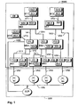
- the network management system NMS is used for administration, in particular Control and monitoring, the network NW, which for example is a computer and / or telecommunications network.
- the network NW is designed as a so-called intelligent network (IN) and contains network elements N1 - N4, which are for example Intermediaries is and exemplifies other, not shown Network elements are.
- the network elements N1 - N4 is a central service computer SCP (Service Control Point) assigned, with the support of the network elements N1 - N4 for subscribers, not shown, connected to the network NW Service of a so-called intelligent network can.
- the service computer SCP and the network elements N1 - N4 communicate via a service network VIN.
- the network management system NMS contains management elements ME1 - ME7 as well as operator terminals BT1 - BT3.
- the management elements ME1 - ME7 may be to act program modules whose program code from computers, for example Servers, the management system NMS can be executed.
- the management elements ME1 - ME7 are each separate servers, for managing one or more network elements and / or one or more several management elements are provided:
- the management elements ME1 and ME2 are for managing the network elements N1 or N2 provided and connected to them via connections VN1 and VN2.
- the management element ME3 is for managing the network elements N3 and N4 and connected to them via links VN3 and VN4, respectively.
- the management element ME4 controls and monitors via a connection VNS the service computer SCP.
- the management element ME4 serves as Transit node or element for passing event information containing the Management element ME1 sends to the management element ME6. It is also possible that the management element ME4 for control and / or monitoring of the management element ME1 or of the network element N1 is.
- the management element ME5 is the management elements ME2 and ME3 assigned and receives from this event information. This leads it in one Function as a transit element to the management elements ME6 and ME7.
- the management element ME5 can also be used for control and / or monitoring the management elements ME2 and / or ME3 or the respectively connected to this Network elements N2 or N3, N4 be provided.
- the management elements ME6 and ME7 are central control computers of the management system NMS and are hierarchical to the management elements ME4 and ME5 superimposed.
- the management system NMS can be operated via the control terminals BT1, BT2 and BT3 be operated by one or more operators.
- the operator terminals BT1 - BT3 are so-called client computers, on which user interfaces GUI1, GUI2 or GUI3 are provided to operate the management system NMS.
- the operator terminal BT1 is connected VT1 with the management element ME6, the operating terminal BT2 via a connection VT2 with the management element ME7 and the operating terminal BT3 Connected via a connection VT3 to the management element ME4.
- LAN Local Area Network
- WAN Wide Area Network
- the network element N1 receives the management element ME1 from this event message, For example, alarms, fault messages, load readings or the like.
- This event information is provided by dispatch discriminators F11 and F12 of the management element ME1 via connections V11 and V12 to the management element ME4 reported.
- the sending discriminators F11 and F12 practice additionally a filter function, i. they only ship for the management element ME4 relevant event information to this. That's what the sending discriminators are for F11, F12 not defined filter criteria predefined.
- send-discriminator F11 only sends critical event information.
- the dispatch discriminator F12 only uncritical event information.
- the send discriminator F11 is a so-called AFD and the send-discriminator F12 to a so-called EVS according to the definitions of the ITU.
- the management element ME4 fulfills several functions: it serves as a transit node for event information of the management element ME1 sent to the Management element ME6. Furthermore, the management element serves ME4 for controlling and / or monitoring a network element, present the service computer SCP. In addition, the management element ME1 via the management element ME4 be controlled and / or monitored. For the sending of event information, for example regarding the management element ME1 and / or the network element SCP, is at the management element ME4 provided the dispatch discriminator F4, which is both critical as also sent uncritical event information. The sending discriminator is for example, a combined AFD and EFD. For control and / or monitoring purposes is the operator terminal BT3 with the management element ME4 connectable.
- the management elements ME2 and ME3 send event information to the Management element ME5.
- the management element ME2 is provided with a send discriminator F2. the via a connection V2 event information, in this case alarm messages, to the management element ME5 sends.
- F2 is a so-called AFD.
- the management element ME3 receives event information from the network elements N3 and N4 in the form of event messages.
- event information of the network element N3 are in the management element ME3 sending discriminators F31 and F32, which are e.g. to an AFD or a EFD handles and event information via links V31 and V32 respectively send the management element ME5.
- the sending discriminator F31 is sent critical event information, the send-discriminator F32 uncritical Event information.
- For the event information of the network element N4 are provided at the management element M3 send discriminators F33 and F34.
- the dispatch discriminator F33 sends out critical event information of the network element N4 via a connection V33 to the management element M5 and is for example a so-called AFD.
- the shipping discriminator F34 at which is, for example, a so-called EVS, sends uncritical Event information of the network element N4 via a connection V34 the management element ME7.
- the management element ME5 serves exclusively as a transit element for forwarding event information of the management elements ME2, ME3 to the management elements ME6 and ME7. In principle it is also conceivable that by means of the management element ME5 the management elements ME2, ME3 or the network elements N2-N4 connected to them can be controlled and / or monitored.
- Present sends the management element ME5 by means of a dispatch discriminator F51 critical event information via a connection V51 to the management element ME6 and uncritical event information via a connection V52 to the management element ME7.
- the sending discriminator F51 is, for example, an AFD, the sending discriminator F52 an EVS.
- connections V11, V12 shown within the management system NMS - V52, VT1 - VT3 are logical connections. In addition to these, other, not shown connections between the management elements ME1 - ME7 and the operator terminals BT1 - BT3.
- the connections V11, V12 - V52 are event information communication links and are exemplary for other event information communication links, not shown between the management elements ME1-ME7 and others, not shown Event information communication connections. Simplifying is also for each communication link shown only one send discriminator. In principle, however, a send discriminator may also have multiple event information communication links serve. Besides, with the management elements ME1 - ME7 shown only a few shipping discriminators.
- a management element is not a sending discriminator exists or any number of send discriminators. In any case, it is already for a NMS management system operator in the configuration shown, it is difficult to get an overview of the event information communication links and / or the existing shipping discriminators to win.
- BT1 - BT3 provided equipped with the invention control modules BC1, BC2 and BC3 are.
- the operating modules BC1 - BC3 interact with response modules BS1 - BS7, which are provided in the management elements ME1 - ME7.
- response modules BS1 - BS7 acts these are program modules whose program code is controlled by
- processors the operator terminals BT1 - BT3 or taxpayers the management elements ME1 - ME7 can be executed.
- the control modules and / or the response modules at least partially implemented in hardware, and for example by the operator terminals BT1 - BT3 and the management elements ME1 - ME7 formed become.
- the control modules BC1 - BC3 receive from the management elements ME1-ME7 Data on the respective existing dispatch discriminators F11, F12, F2, F31, F32, F33, F34, F4, F51 and F52.
- the management elements ME1 - ME7 the data about their respective sending discriminators spontaneously, i. without prior request, to the operating modules BC1 - BC3 or any other facility of the management system NMS, for example a central database.
- the operating modules BC1 - BC3 ask the response modules BS1 - BS7 derives the respective data via existing send discriminators. The questions are answered by the answer modules BS1 - BS7.
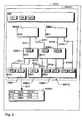
- This determined data is provided by the operating module BC1 on a user interface GUI of the control terminal BT1, the control module BC2 on a user interface GUI2 of the operating terminal BT2 and the operating module BC3 on a user interface GUI3 of the operator terminal BT3 each in the manner of an event information network representing map MAP1, MAP2 and MAP3.
- an operator of the NMS management system activates on the user interface GUI1 of the operator terminal BT1 the control module BC1.
- the operator makes a start window of the user interface GUI1 corresponding operator input, whereupon the operating module BC1 e.g. in the foreground the user interface GUI1 occurs and / or the operator terminal BT1 Program code of the operating module BC1 begins to execute.
- the operating module BC1 sends with query and / or connection means, for example a query function REQ, also called a separate query submodule can be configured, or a connection function TRV, to the Answer module BS6 a query to determine about in the management system NMS existing send discriminators.
- a query function REQ also called a separate query submodule can be configured, or a connection function TRV
- TRV connection function
- the answer module BS6 determines the in Management system NMS existing management elements.
- the names and / or addresses of the management elements may be at the answer module BS6 be stored, for example in the form of configuration data.
- the answer module BS6 asks the respective data in a so-called Name server NS6, which in this case is a program module, which is executed by the management element ME6.
- the answer module BS6 the names and / or addresses of the management elements of the management system queries NMS from a separate database, for example, a database DB.
- a database DB e.g. central Data of the management system NMS filed and queried by its elements.
- the response module BS6 then builds connections to the management elements ME4 and ME5 and instructs them, the data on the sending discriminators the management elements associated with each of them to investigate.
- the management element ME4 or its response module BS4 then sends a corresponding query to the management element ME1.
- a response module BS1 of the management element ME1 then sends the corresponding Data on the send discriminators F11 and F12 to the answer module BS4. This sends this data as well as the data via the send discriminator F4 of the management element ME4 to the response module BS6.
- a response module BS5 of the management element ME5 sends to the query of the answering module BS6 concerning the sending discriminators F51 and F52 Data F51 D and F52D with response means ANS, for example a response function to the answer module BS6.
- the answer module BS5 further determines with help a name server NS5 of the management element ME5, which management elements are connected to the management element ME5.
- Answer module BS5 with query means ASK for example, a query function
- ASK for example, a query function
- Queries to the management elements ME2, ME3 and ME7 for example to their response modules BS2, BS3 or BS7 to the data - or at least one Part of the data - about the management elements ME2, ME3 or ME7 to identify any existing shipping discriminators.
- the response module BS2 sends data via the Send-discriminator F2 and the answer module BS3 by means of responses ANS, for example, a response function, data F31D, F32D, F33D, F34D, the the shipping discriminators F31, F32 F33 and F34, respectively.
- responses ANS for example, a response function
- data F31D, F32D, F33D, F34D the shipping discriminators F31, F32 F33 and F34
- the shipping discriminators F31, F32 F33 and F34 respectively.
- data F31D is for example the type of shipping discriminator, e.g. AFD or EFD, the name of the sending discriminator, the destination to which the dispatch discriminator provides event information sends its status ("disabled", "enabled", "locked” or "unlocked"), or similar.
- Management element ME7 does not have a send-discriminator. Accordingly, the response module BS7 sends a response as indicated is that the management element ME7 has no sending discriminators are.
- the data received by the management elements ME4 and ME5 7 about sending discriminators the response module BS6 reports to the operating module BC1, which from this data, so to speak, an event information network of the management system NMS determined.
- the queries regarding send-discriminators so to speak, cascading or in a kind of snowball system between the management elements ME1 - ME7 sent, being a management element each its adjacent and / or hierarchically superimposed and / or subordinate management elements by their respective sending discriminators asks.
- an operating module and / or a response module associated therewith For example, the adjustment module BC1 or the response module BS6 of Management element ME6, the data about the respective sending discriminators for the management elements ME1 - ME5, ME7 directly - without participation Intermediate response modules - queries.
- the Control module BC1 has the functionality of the response module BS6.
- the operating module BC1 has in such an embodiment via query means, with with a selection of management elements, if necessary with all Management elements of the network management system NMS data can query about their respective send-discriminators.
- the analysis means ANA of the operating module BC1 determine the communication links V11, V12-V52 between the management elements ME1-ME7 and outputs the data thus determined to the output means OUT, which can also be designed as a separate output submodule can, further, generate the MAP1 from this data and output GUI GUI1 in the form of a window WIN11. If the operating terminal BT1 has, for example, a so-called X-Window environment, the window WIN11 can be generated, for example, by X-window functions of the operating module BC1. However, it is also possible for the operating module BC1 to commission a suitable user interface module, for example the user interface module UI, with the output of the card MAP1.
- a suitable user interface module for example the user interface module UI
- the user interface module UI is, for example, a browser which is suitable for outputting of graphics data and / or data in a so-called mark-up language such as the HTML (H t ext yper M arkup L anguage). It is understood that combinations of both forms of output are possible, as will become apparent below.
- the window WIN11 is generated by the operating module BC1 itself and the window WIN12 by the operating surface module UI.
- the window WIN11 shows the map MAP1 with graphical representations or Symbols SME1 - SME7 of the management elements ME1 - ME7. Further is at the window WIN11 a menu bar and / or button bar MB provided with the various functions of the operating module BC1 can be activated. For example is a menu and / or button FIL provided, with which the window WIN11 closed and / or the map MAP1 can be stored in a file. Furthermore, a menu or button VW is provided, on the different forms of presentation Map MAP1 are available. The menu item VW can also be provided to update the map MAP1, so to speak, again Queries about the sending discriminators to the management elements ME1 - ME7, as already explained above, are shipped. About a menu NAV can to navigated to other windows and / or applications of the user interface GUI1 become.
- V11, V12, V2, V31, V32, V33, V34, V4, V51, V52 are these plotting symbols SV11, SV12, SV2, SV31, SV32, SV33, SV34, SV4, SV51 and SV52, respectively, on the MAP1 card shown.
- the symbols SV11 - SV52 are MAP1 lines with one Arrow end, which is the shipping direction of each sent event information represents.
- Each symbol SV11 - SV52 symbolizes one dispatch discriminator F11 - F52.
- the symbols SV11 - SV52 show the type of the respective sending discriminator: A continuous line stands for one EFD, a dashed line for an AFD.
- a symbol could also be animated
- a symbol could be a communication link originating from an AFD represents, flashing.
- the map MAP1 be graphically illustrated.
- the mailer is discriminator F34 locked in a state where it has no event information sends.
- the symbol SV34 is the communication link V34 a dash-dotted line. It would also be possible for one or multiple blocked and / or inactive communication links Symbol SV34 visually in the background, for example, by a representation in a relatively neutral, e.g. gray, color.
- various views of the map MAP1 can be activated be, for example, the present view, in which all communication links are shown between the management elements ME1 - ME7 or two further views, not shown, in which either either of AFDs or the communication links served by EFDs are shown.
- the card MAP1 is activated by the window WIN12, that is, the operating module BC1 creates the WIN12 window for the first time or first in the background of the user interface GUI1 window WIN12 is activated in the Foreground dazzled.
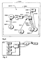
- ACT activates the icon SME2 and / or the symbol SV2, e.g. with a mouse click or a keyboard entry, the window WIN12 is started, which data via the send discriminator F2 of the management element ME2 outputs.
- the Status "disabled” or “enabled” is output in selection fields DISA or ENA.
- the selection field ENA is marked by a dot, i.e., the sending discriminator F2 is "enabled".
- data from Shipping discriminators also be modified.
- the status of the send discriminator F2 be changed.
- the selection field DISA be marked, the mark in the Selection box ENA automatically disappears.
- Modifier MOD of the operator terminal BC1 detect this change and send via the connection means TRV corresponding modification commands to the management element ME2.
- the operating module BC2 of the operating terminal which can be started from the user interface GU12 BT2 shows another variant of the invention, but is in its Basic functions have the same structure as the operating module already explained BC1.
- the operating module sends BC1 queries data from shipping discriminators of the management system NMS to the response module BS7.
- This is determined by internal Data MLIS, which are for example configuration data, in the management system NMS existing management elements and sends to these queries about their sending discriminators.
- the appropriate Query cascade to the management elements ME4 and ME5 and from proceeding from this to the management elements ME6, ME1, ME2, ME3 be shipped.
- the answer module BS7 immediately to the management elements ME1 - ME6 a corresponding query Sends data via their respective sending discriminators.
- the BC2 programming module on the user interface GUI2 first a window WIN21.
- the window WIN21 Just like the window WIN12 of the Control module BC1 also contains the window WIN21 a menu bar MB, which in is about the same structure and / or works like the same menu bar MB of the window WIN11.
- the window WIN21 contains the map MAP2, which another form of output for the event information network of the management system NMS shows.
- the symbols SME1 - SME7 for the management elements ME1 - ME7 are like the symbols of the same name MAP1 abstract geometric representations, however, at least partially in the map MAP2 are designed differently than the MAP1.
- management symbols ME1-ME7 representing symbols SME1-SME7 on the respective cards MAP1, MAP2 by color and / or geometric or any other visually detectable Design a function and / or a state of the respective associated management element can play.
- the symbols SME1-SME7 are in a hierarchical manner in the map MAP2 arranged. With the map MAP2, the hierarchy also gives the hierarchical Control and monitoring function of the management elements ME1 - ME7 again. But it is also possible that a card with a purely functional, not hierarchical representation is output.
- map MAP2 also illustrates the direction in which Event information is transmitted: in this case from bottom to top. Therefore, the symbols SV11-SV52 in the map MAP2 are merely simple lines, without a component that clarifies the respective transmission direction, for example, an arrowhead. Furthermore MAP2 with "AFD”, “EFD” or “XFD” designated symbols for the dispatch discriminators F11-F52 at presented to the management elements ME1 - ME5. Each of the symbols "AFD”, “EFD” or “XFD” can each be for one or more AFDs, EFDs or combined AFDs and EFDs are available. In this context should also be mentioned each symbol SV11 - SV52 for one or more event information communication links can stand.
- send discriminators available from the window WIN21. For example, upon activation ACT of the symbol SME1 the window WIN22 will be started.
- the control module BC2 sends in this For example, a table to a browser, e.g. a Netscape Navigator or a Microsoft Internet Explorer, or even creates the window WIN22.
- the table names are NAM of the dispatch discriminators F11 and F22 in FIG a first column, as well as their respective destination (or respective destinations) for sending specified by event information and their respective status.
- the table of the window WIN22 too may contain further information, for example an application program the server ME4 as an exact destination and / or other state information, for example Locked / Unlocked and / or Enabled / Disabled. It is also conceivable that the indications in the table of window WIN22 are modifiable, i. that For example, the name of the discriminator F11 can be changed to "F13".
- the corresponding change information is sent by the BC2 programming module then to the relevant management element.
- a preferred variant of the invention provides that, for example, via the Menu VW, a window, not shown in the figure, is started with e.g. the control module BC2 outputs a table in which data of each one at a Management element ME1 - ME7 existing send-discriminators or in of the total data of all the management elements ME1-ME7 Dispatch discriminators F11, F12, F2, F31-F34, F4, F51, F52 are.
- the respective table can be used by the operating module BC2 for outputting to a Browser and / or in a self-generated representation, e.g. in a self-generated window.
- the operating module BC3 of the operating terminal BT3 asks in one of the previously mentioned Wise, for example, with the help of the answer module BS4 data via dispatch discriminators in the management elements ME1 - ME7. It is also possible that the control module BC3 the data itself at the relevant Management elements ME1 - ME7 queries. In any case, the operating module generates BC3 from this data the map MAP3 in a window WIN3 on the User interface GUI3. Compared to the maps MAP1, MAP2 are at the Map MAP3 the symbols SME1 - SME7 for the management elements ME1 - ME7 designed differently and give at least partially the or by they respectively visually manage managed network elements. They are, in a way meaningful:
- the management elements ME1 and ME2 each manage an exchange as a network element. Accordingly, the symbols SME1, SME2 are as Switchboard icons shown. Manages the management element ME3 present two exchanges as network elements, which is why the symbol SME3 of management element ME3 implies two exchanges.
- the Symbol SME4 is intended to illustrate the service computer SCP, which is represented by the Management element ME4 is managed.
- the symbols SV11-SV52 for the event information communication links V11 - V52 correspond to those of MAP1. Based on the map MAP3 it becomes clear that a hierarchical and / or functional representation of the management elements ME1 - ME7 useful, but not mandatory is. For example, the management elements of the respective operating module be arranged on the respective card that the communication links between these are shown as possible without crossing.
- FIG. 8 shows, by way of example, the operating terminal BT1
- FIG. 9 shows an example the management element ME6.
- the operator terminals BT2 and BT3 or the management elements ME1 - ME5, ME7 are functionally the same as the one Operator terminal BT1 or the management element ME6.
- the computers BT1, ME6 contain communication means KOM, for example, LAN interface cards or the like.
- the input means IN are, for example, a keyboard, a Mouse, a microphone or the like.
- the output means OU are for example, a monitor, a speaker or the like.
- the control means CPU led program code of program modules, at the operator terminal BT1, for example, the user interface module UI and the operating module BC1, off, which are stored in the memory means MEM. Not shown are at the computers BT1, ME6 each an operating system, such as UNIX or Windows NT, which controls the basic functions of the respective computer BT1, ME6 and monitored.
- ORB Object Request Broker
- CORBA Common Object Request Broker Architecture
Landscapes
- Engineering & Computer Science (AREA)
- Signal Processing (AREA)
- Computer Networks & Wireless Communication (AREA)
- Human Computer Interaction (AREA)
- Data Exchanges In Wide-Area Networks (AREA)
Claims (14)
- Procédé pour administrer un système de gestion de réseau (NMS) comprenant des éléments de gestion (ME1-ME7) qui peuvent, au moyen de discriminateurs d'émission (F11, F12, F2, F31-F34, F4, F51, F52), envoyer des informations d'événement par le biais de liaisons de communication d'informations d'événement (V11, V12, V2, V31-V34, V4, V51, V52) à l'aide desquelles les éléments de gestion (ME1 - ME7) ct/ou les éléments de réseau (NA - N4, SCP) administrés par eux peuvent être administrés, caractérisé en ce queun module de commande (BC1, BC2, BC3) pour une sélection d'éléments de gestion (ME1-ME7) détermine entre ceux-ci les liaisons de communication d'informations d'événement (V11, V12, V2, V31 - V34, V4, V51, V52) existantes entre ceux-ci à l'aide de données (F31D-F34D, F51D, F52D) sur des discriminateurs d'émission (F11, F12, F2, F31-F34, F4, F51, F52), lesquels commandent auprès des éléments de gestion (ME1-ME7) les liaisons de communication d'informations d'événement (V11, V12, V2, V31-V34, V4, V51, V52) respectives, etle module de commande (BC1, BC2, BC3) public les éléments de gestion (ME1-ME7) de la sélection ainsi que les liaisons de communication d'informations d'événement (V11, V12, V2, V31-V34, V4, V51, V52) à chaque fois présentes dans une carte (MAP1, MAP2, MAP3) représentant un réseau d'informations d'événement sous forme graphique sur une interface utilisateur (GUI1-GUI3) du système de gestion de réseau (NMS).
- Procédé selon la revendication 1, caractérisé en ce que le module de commande (BC1, BC2, BC3) détermine pour au moins une liaison de communication d'informations d'événement (V11, V12, V2, V31-V34, V4, V51, V52) au moins une information (NAM, TAR, STAT) concernant le discriminateur d'émission (F11, F12, F2, F31-F34, F4, F51, F52) participant à la liaison de communication d'informations d'événement (V11, V12, V2, V31 - V34, V4, V51, V52) et visualise l'au moins une information sur la carte (MAP1, MAP2, MAP3).
- Procédé selon la revendication 1, caractérisé en ce que les éléments de gestion (ME1-ME7) de la sélection sont publiés sous la forme de symboles (SME1-SME7) pour des noeuds de réseau d'informations d'événement et/ou que les liaisons de communication (V11, V12, V2, V31 - V34, V4, V51, V52) sont publiées sous la forme de symboles (SV11, SV12, SV2, SV31 - SV34, SV4, SV51, SV52) entre les symboles (SME1-SME7) des éléments de gestion (ME1-ME7).
- Procédé selon la revendication 1, caractérisé en ce que le module de commande (BC1, BC2, BC3) publie les données sur les discriminateurs d'émission (F11, F12, F2, F31-F34, F4, F51, F52) des éléments de gestion (ME1-ME7) de la sélection au moins partiellement en caractères alphanumériques.
- Procédé selon la revendication 1, caractérisé en ce que le module de commande (BC1, BC2, BC3) interroge les données sur les discriminateurs d'émission (F11, F12, F2, F31-F34, F4, F51, F52) auprès des éléments de gestion (ME1-ME7).
- Procédé selon la revendication 1, caractérisé en ce qu'un module partiel d'interrogation (REQ) du module de commande (BC1, BC2, BC3) interroge les données sur les discriminateurs d'émission (F11, F12, F2, F31 - F34, F4, F51, F52) auprès des éléments de gestion (ME1-ME7) et un module partiel d'affichage (OUT) du module de commande (BC1, BC2, BC3) publie sous forme graphique les éléments de gestion (ME1-ME7) de la sélection ainsi que les liaisons de communication d'informations d'événement (V11, V12, V2, V31-V34, V4, V51, V52) à chaque fois présentes entre eux.
- Procédé selon la revendication 1, caractérisé en ce qu'au niveau d'au moins un élément de gestion (ME1-ME7) un module de réponse (BS1-BS7) associé au module de commande (BC1, BC2, BC3) envoie au module de commande (BC1, BC2, BC3) des données sur au moins un discriminateur d'émission (F11, F12, F2, F31-F34, F4, F51, F52) de l'élément de gestion (ME1-ME7).
- Procédé selon la revendication 1, caractérisé en ce que le module de commande (BC1, BC2, BC3) interroge la sélection des éléments de gestion (ME1-MF7) auprès d'un serveur de nom (NS6, NS5) du système de gestion de réseau (NMS).
- Module de commande (BC1, BC2, BC3) destiné à administrer un système de gestion de réseau (NMS) comprenant des éléments de gestion (ME1-MF7) qui, au moyen de discriminateurs d'émission (F11, F12, F2, F31 - F34, F4, F51, F52), envoient des informations d'événement à l'aide desquelles les éléments de gestion (ME1-ME7) et/ou les éléments de réseau (NA - N4, SCP) administrés par eux sont administrés,comprenant des moyens d'analyse (ANA) pour déterminer des liaisons de communication d'informations d'événement (V11, V12, V2, V31 - V34, V4, V51, V52) entre une sélection d'éléments de gestion (ME1-ME7) à l'aide de données sur des discriminateurs d'émission (F11, F12, F2, F31 - F34, F4, F51, F52), lesquels commandent auprès des éléments de gestion (ME1 - ME7) les liaisons de communication d'informations d'événement (V11, V12, V2, V31 - V34, V4, V51, V52) respectives, etcomprenant des moyens de sortie (OUT) pour la publication graphique des éléments de gestion (ME1-ME7) de la sélection ainsi que des liaisons de communication d'informations d'événement (V11, V12, V2, V31 - V34, V4, V51, V52) à chaque fois présentes entre eux dans une carte (MAP1, MAP2, MAP3) représentant un réseau d'informations d'événement sur une interface utilisateur (GUI1-GUI3) du système de gestion de réseau (NMS).
- Module de commande (BC1, BC2, BC3) selon la revendication 9, caractérisé en ce qu'il est réalisé sous la forme d'un système de gestion de réseau (NMS) informatisé.
- Module de commande (BC1, BC2, BC3) selon la revendication 9, caractérisé en ce que les données de la carte (MAP1, MAP2, MAP3) générée par le module de commande peuvent au moins en partie être modifiées en partant d'au moins un discriminateur d'émission (F11, F12, F2, F31 -F34, F4, F51, F52).
- Module de commande (BC1, BC2, BC3) selon la revendication 9, caractérisé en ce qu'il comprend un code de programme qui est exécuté par un moyen de commande d'un système de gestion de réseau (NMS) informatisé.
- Système de gestion de réseau (NMS) ou ordinateur d'un système de gestion de réseau (NMS) comprenant au moins un module de commande (BC1, BC2, BC3) selon la revendication 9.
- Moyen de mémorisation lisible par un ordinateur comprenant un code de module de commande (BC1, BC2, BC3) enregistré sur celui-ci et destiné à administrer un système de gestion de réseau (NMS) comprenant des éléments de gestion (ME1-ME7) qui, au moyen de discriminateurs d'émission (F11, F12, F2, F31 - F34, F4, F51, F52), envoient des informations d'événement à l'aide desquelles les éléments de gestion (ME1 - ME7) et/ou les éléments de réseau (NA - N4, SCP) administrés par eux sont administrés, le code de module de commande (BC1, BC2, BC3) étant configuré de telle sorte que, lorsqu'il est exécuté par les moyens de commande d'un ordinateur du système de gestion de réseau,détermine des liaisons de communication d'informations d'événement (V11, V12, V2, V31-V34, V4, V51, V52) entre une sélection d'éléments de gestion (ME1-ME7) à l'aide de données sur des discriminateurs d'émission (F11, F12, F2, F31-F34, F4, F51, F52), lesquels commandent auprès des éléments de gestion (ME1-ME7) les liaisons de communication d'informations d'événement (V11, V12, V2, V31 - V34, V4, V51, V52) respectives, etpublie sous forme graphique les éléments de gestion (ME1-ME7) de la sélection ainsi que des liaisons de communication d'informations d'événement (V11, V12, V2, V31 - V34, V4, V51, V52) à chaque fois présentes entre eux dans une carte (MAP1, MAP2, MAP3) représentant un réseau d'informations d'événement sur une interface utilisateur (GUI1-GUI3) du système de gestion de réseau (NMS).
Priority Applications (3)
| Application Number | Priority Date | Filing Date | Title |
|---|---|---|---|
| DE50107756T DE50107756D1 (de) | 2001-08-21 | 2001-08-21 | Verfahren, Bedienmodul und Antwortmodul zur Verwaltung eines Netzwerk-Management-Systems |
| EP01440280A EP1286499B1 (fr) | 2001-08-21 | 2001-08-21 | Procédé et module de commande pour administrer un système de gestion de réseau |
| US10/217,428 US20030038833A1 (en) | 2001-08-21 | 2002-08-14 | Method, operator module an response module for managing a network management system |
Applications Claiming Priority (1)
| Application Number | Priority Date | Filing Date | Title |
|---|---|---|---|
| EP01440280A EP1286499B1 (fr) | 2001-08-21 | 2001-08-21 | Procédé et module de commande pour administrer un système de gestion de réseau |
Publications (2)
| Publication Number | Publication Date |
|---|---|
| EP1286499A1 EP1286499A1 (fr) | 2003-02-26 |
| EP1286499B1 true EP1286499B1 (fr) | 2005-10-19 |
Family
ID=8183293
Family Applications (1)
| Application Number | Title | Priority Date | Filing Date |
|---|---|---|---|
| EP01440280A Expired - Lifetime EP1286499B1 (fr) | 2001-08-21 | 2001-08-21 | Procédé et module de commande pour administrer un système de gestion de réseau |
Country Status (3)
| Country | Link |
|---|---|
| US (1) | US20030038833A1 (fr) |
| EP (1) | EP1286499B1 (fr) |
| DE (1) | DE50107756D1 (fr) |
Families Citing this family (1)
| Publication number | Priority date | Publication date | Assignee | Title |
|---|---|---|---|---|
| US20030200347A1 (en) * | 2002-03-28 | 2003-10-23 | International Business Machines Corporation | Method, system and program product for visualization of grid computing network status |
Family Cites Families (4)
| Publication number | Priority date | Publication date | Assignee | Title |
|---|---|---|---|---|
| US5295244A (en) * | 1990-09-17 | 1994-03-15 | Cabletron Systems, Inc. | Network management system using interconnected hierarchies to represent different network dimensions in multiple display views |
| SE503021C2 (sv) * | 1994-06-13 | 1996-03-11 | Ericsson Telefon Ab L M | Driftstödsnät för ett telekommunikationsnät innefattande nätelement, telekommunikationsnät innefattande nätelement, nätelement samt sätt att strukturera programvara i ett nätelement |
| US5913036A (en) * | 1996-06-28 | 1999-06-15 | Mci Communications Corporation | Raw performance monitoring correlated problem alert signals |
| JP3266126B2 (ja) * | 1999-01-14 | 2002-03-18 | 日本電気株式会社 | ネットワーク障害情報管理システム及び記憶媒体 |
-
2001
- 2001-08-21 EP EP01440280A patent/EP1286499B1/fr not_active Expired - Lifetime
- 2001-08-21 DE DE50107756T patent/DE50107756D1/de not_active Expired - Lifetime
-
2002
- 2002-08-14 US US10/217,428 patent/US20030038833A1/en not_active Abandoned
Also Published As
| Publication number | Publication date |
|---|---|
| DE50107756D1 (de) | 2006-03-02 |
| US20030038833A1 (en) | 2003-02-27 |
| EP1286499A1 (fr) | 2003-02-26 |
Similar Documents
| Publication | Publication Date | Title |
|---|---|---|
| DE69810181T2 (de) | Verbreitungsschema für Netzwerkobjektstatus | |
| EP1110127B1 (fr) | Systeme d'information, de commande et/ou d'observation avec interface utilisateur modelisee et procedes de commande et/ou d'observation modelisees | |
| DE69132280T2 (de) | System und Verfahren zur Modellierung eines Computer-Netzwerks | |
| DE60109709T2 (de) | Datenverwaltungsrahmenwerk für Verfahrensverwaltung | |
| DE10051021B4 (de) | System, Verfahren und Computerprogramm zur Bereitstellung interaktiver Web-Inhalte in statisch verknüpften Dateien | |
| DE69325830T2 (de) | Arbeitsgruppen-CAD-System und Verfahren zum gemeinsamen Entwerfen | |
| EP3480672B1 (fr) | Procédé de détection et d'affichage d'accès d'opérateur à des objets de traitement ainsi que système d'exploitation | |
| DE10048653A1 (de) | Digitales Verzeichnis zur Verwendung in einem Kommunikationssystem | |
| EP1286497B1 (fr) | Procédé pour la représentation graphique de l' état de noeuds de réseau dans un réseau surveillé, et système de surveillance et module de programme associé | |
| DE10161115A1 (de) | Transformation von Objektbäumen, insbesondere in MES-Systemen | |
| EP2876512A1 (fr) | Procédé pour générer automatiquement des connections entre composants d'un modèle d'un système technique | |
| EP1286499B1 (fr) | Procédé et module de commande pour administrer un système de gestion de réseau | |
| WO2008148238A1 (fr) | Télécommande de programme de navigation | |
| EP2249219A2 (fr) | Procédé de sélection d'un système de communication agencé dans un réseau de transmission d'un système d'automatisation | |
| EP0797330B1 (fr) | Réseau d'ordinateurs et méthode de gestion correspondante | |
| EP1655663A1 (fr) | Modélisation d'un flux de données dans les systèmes d'ingénierie | |
| EP1561172B1 (fr) | Dispositif offrant l'acces a des donnees | |
| DE19914819A1 (de) | Entwicklungswerkzeug | |
| DE10033812A1 (de) | Verfahren zum Erzeugen von Informationsmodellen | |
| DE10319887B4 (de) | Verfahren zum Angleichen eines auf einer Client-Datenverarbeitungseinrichtung angezeigten Datenbestandes an einen auf einer Server-Datenverarbeitungseinrichtung gespeicherten Quelldatenbestand | |
| EP1195946A2 (fr) | Procédé pour la mise à disposition de services dans un système de gestion de réseau avec architecture ouverte et avec des objets de service, des objets de requête et un gestionnaire de requêtes | |
| DE10065323C2 (de) | Verfahren zur Steuerung der Anordnung von graphischen Elementen | |
| EP1051671A1 (fr) | Systeme de transmission de donnees ou d'informations | |
| EP1286261A1 (fr) | Méthode, module d'interface de commande, modules intermédiaires et ainsi équipé système de gestion de réseau pour le fonctionnement d'un module d'interface de commande | |
| EP0973091A2 (fr) | Méthode pour générer un réseau contrôlable et adaptable des modèles de gabarits de comportement |
Legal Events
| Date | Code | Title | Description |
|---|---|---|---|
| PUAI | Public reference made under article 153(3) epc to a published international application that has entered the european phase |
Free format text: ORIGINAL CODE: 0009012 |
|
| 17P | Request for examination filed |
Effective date: 20020622 |
|
| AK | Designated contracting states |
Kind code of ref document: A1 Designated state(s): AT BE CH CY DE DK ES FI FR GB GR IE IT LI LU MC NL PT SE TR |
|
| AX | Request for extension of the european patent |
Extension state: AL LT LV MK RO SI |
|
| AKX | Designation fees paid |
Designated state(s): DE ES FR GB IT |
|
| GRAP | Despatch of communication of intention to grant a patent |
Free format text: ORIGINAL CODE: EPIDOSNIGR1 |
|
| RTI1 | Title (correction) |
Free format text: METHOD AND CONTROL MODULE FOR ADMINISTRATING A NETWORK MANAGEMENT SYSTEM |
|
| GRAS | Grant fee paid |
Free format text: ORIGINAL CODE: EPIDOSNIGR3 |
|
| GRAA | (expected) grant |
Free format text: ORIGINAL CODE: 0009210 |
|
| AK | Designated contracting states |
Kind code of ref document: B1 Designated state(s): DE ES FR GB IT |
|
| REG | Reference to a national code |
Ref country code: GB Ref legal event code: FG4D Free format text: NOT ENGLISH |
|
| GBT | Gb: translation of ep patent filed (gb section 77(6)(a)/1977) |
Effective date: 20051125 |
|
| PG25 | Lapsed in a contracting state [announced via postgrant information from national office to epo] |
Ref country code: ES Free format text: LAPSE BECAUSE OF FAILURE TO SUBMIT A TRANSLATION OF THE DESCRIPTION OR TO PAY THE FEE WITHIN THE PRESCRIBED TIME-LIMIT Effective date: 20060130 |
|
| REF | Corresponds to: |
Ref document number: 50107756 Country of ref document: DE Date of ref document: 20060302 Kind code of ref document: P |
|
| ET | Fr: translation filed | ||
| PLBE | No opposition filed within time limit |
Free format text: ORIGINAL CODE: 0009261 |
|
| STAA | Information on the status of an ep patent application or granted ep patent |
Free format text: STATUS: NO OPPOSITION FILED WITHIN TIME LIMIT |
|
| 26N | No opposition filed |
Effective date: 20060720 |
|
| REG | Reference to a national code |
Ref country code: GB Ref legal event code: 732E Free format text: REGISTERED BETWEEN 20131003 AND 20131009 |
|
| REG | Reference to a national code |
Ref country code: FR Ref legal event code: GC Effective date: 20140717 |
|
| REG | Reference to a national code |
Ref country code: FR Ref legal event code: RG Effective date: 20141016 |
|
| REG | Reference to a national code |
Ref country code: FR Ref legal event code: PLFP Year of fee payment: 15 |
|
| REG | Reference to a national code |
Ref country code: FR Ref legal event code: PLFP Year of fee payment: 16 |
|
| REG | Reference to a national code |
Ref country code: FR Ref legal event code: PLFP Year of fee payment: 17 |
|
| PGFP | Annual fee paid to national office [announced via postgrant information from national office to epo] |
Ref country code: FR Payment date: 20170822 Year of fee payment: 17 Ref country code: DE Payment date: 20170822 Year of fee payment: 17 Ref country code: IT Payment date: 20170828 Year of fee payment: 17 Ref country code: GB Payment date: 20170822 Year of fee payment: 17 |
|
| REG | Reference to a national code |
Ref country code: DE Ref legal event code: R119 Ref document number: 50107756 Country of ref document: DE |
|
| GBPC | Gb: european patent ceased through non-payment of renewal fee |
Effective date: 20180821 |
|
| REG | Reference to a national code |
Ref country code: GB Ref legal event code: 732E Free format text: REGISTERED BETWEEN 20190429 AND 20190502 |
|
| REG | Reference to a national code |
Ref country code: DE Ref legal event code: R082 Ref document number: 50107756 Country of ref document: DE Representative=s name: MENZIETTI WETZEL, DE Ref country code: DE Ref legal event code: R081 Ref document number: 50107756 Country of ref document: DE Owner name: PROVENANCE ASSET GROUP LLC, PITTSFORD, US Free format text: FORMER OWNER: ALCATEL LUCENT, PARIS, FR |
|
| PG25 | Lapsed in a contracting state [announced via postgrant information from national office to epo] |
Ref country code: DE Free format text: LAPSE BECAUSE OF NON-PAYMENT OF DUE FEES Effective date: 20190301 Ref country code: IT Free format text: LAPSE BECAUSE OF NON-PAYMENT OF DUE FEES Effective date: 20180821 |
|
| PG25 | Lapsed in a contracting state [announced via postgrant information from national office to epo] |
Ref country code: FR Free format text: LAPSE BECAUSE OF NON-PAYMENT OF DUE FEES Effective date: 20180831 |
|
| PG25 | Lapsed in a contracting state [announced via postgrant information from national office to epo] |
Ref country code: GB Free format text: LAPSE BECAUSE OF NON-PAYMENT OF DUE FEES Effective date: 20180821 |