EP1286785B1 - Wagonnet de peinture extensible avec mecanisme d'entrainement a cremaillere - Google Patents
Wagonnet de peinture extensible avec mecanisme d'entrainement a cremaillere Download PDFInfo
- Publication number
- EP1286785B1 EP1286785B1 EP01949116A EP01949116A EP1286785B1 EP 1286785 B1 EP1286785 B1 EP 1286785B1 EP 01949116 A EP01949116 A EP 01949116A EP 01949116 A EP01949116 A EP 01949116A EP 1286785 B1 EP1286785 B1 EP 1286785B1
- Authority
- EP
- European Patent Office
- Prior art keywords
- rack
- cars
- paint
- wagon
- paint wagon
- Prior art date
- Legal status (The legal status is an assumption and is not a legal conclusion. Google has not performed a legal analysis and makes no representation as to the accuracy of the status listed.)
- Expired - Lifetime
Links
Images




Classifications
-
- B—PERFORMING OPERATIONS; TRANSPORTING
- B05—SPRAYING OR ATOMISING IN GENERAL; APPLYING FLUENT MATERIALS TO SURFACES, IN GENERAL
- B05B—SPRAYING APPARATUS; ATOMISING APPARATUS; NOZZLES
- B05B13/00—Machines or plants for applying liquids or other fluent materials to surfaces of objects or other work by spraying, not covered by groups B05B1/00 - B05B11/00
- B05B13/02—Means for supporting work; Arrangement or mounting of spray heads; Adaptation or arrangement of means for feeding work
- B05B13/0285—Stands for supporting individual articles to be sprayed, e.g. doors, vehicle body parts
-
- B—PERFORMING OPERATIONS; TRANSPORTING
- B05—SPRAYING OR ATOMISING IN GENERAL; APPLYING FLUENT MATERIALS TO SURFACES, IN GENERAL
- B05B—SPRAYING APPARATUS; ATOMISING APPARATUS; NOZZLES
- B05B13/00—Machines or plants for applying liquids or other fluent materials to surfaces of objects or other work by spraying, not covered by groups B05B1/00 - B05B11/00
- B05B13/02—Means for supporting work; Arrangement or mounting of spray heads; Adaptation or arrangement of means for feeding work
- B05B13/0221—Means for supporting work; Arrangement or mounting of spray heads; Adaptation or arrangement of means for feeding work characterised by the means for moving or conveying the objects or other work, e.g. conveyor belts
Definitions
- the present invention relates to a paint wagon for carrying a plurality of components to be painted through a painting facility.
- this invention relates to an expandable paint wagon which can be easily expanded and contracted at desired locations.
- Paint wagons are commonly used to carry exterior components of motor vehicles through a paint facility.
- United States Patent no. 5,772,233 describes a typical paint wagon used for two tone fascias corresponding to the preamble of claim 1. The paint wagon contracts prior to entry into the paint facility so that one fascia will partially shroud a next adjacent fascia. After painting, the wagon expands to allow removal of the fascia from the wagon.
- paint wagons are not expandable and have mounting fixtures which are rigidly mounted to the wagon. These wagons are used primarily because they are easy to build and have no moving parts which can foul with each trip through the paint facility.
- fixed mount paint wagons limit the throughput of the paint facility since each wagon requires a minimum of space along the conveyor to allow the wagons to run comers.
- the fascia must be spaced apart to allow the painting robot to fit between the parts and to allow the mounting and removal of the fascia onto and from the paint wagon. At other times, the non-expandable wagons take up valuable space along the conveyor system.
- the expandable wagon as described in United States patent no. 5,772,233 could easily be modified to expand prior to entry into the paint facility and contract after and at other desired locations.
- the prior art expandable wagons require contact with a fixed rigid structure to expand and contract.
- a pole is mounted on the floor adjacent the travel of the paint wagons to effect the movement of the paint wagon.
- these poles would present safety problems.
- the greater number of poles may interfere with other fixtures mounted on the paint wagons.
- Other fixtures are utilized when parts other than fascia are required to be painted.
- the addition of poles is not a safe and economical solution to modifying paint wagon length.
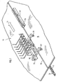
- an expandable paint wagon 10 of the present invention is shown.
- the paint wagon 10 travels along a conveyor 12 in the direction indicated at 14.
- the conveyor 12 is conventionally mounted below floor 16 and accessed through a slot 18.
- Actuating mechanism 20 is mounted on the floor 16 adjacent to the slot 18.
- Actuating mechanism 20 is generally elongate and extends in the same general direction as the slot 18.
- the paint wagon 10 generally comprises a base frame 22, an actuating assembly 24 and a fixture mounting assembly 26.
- Actuating assembly 24 is mounted on the base frame 22.
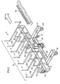
- Fixture mounting assembly 26 is operably mounted on the actuating assembly 24 for responsive movement between an expanded condition ( Figure 2) and a contracted condition ( Figure 1).
- the actuating assembly 24 comprises an elongated C-shaped longitudinal support 38 having closed ends 40.
- Longitudinal support 38 is mounted on spacers 36.
- An elongate channel 42 extends longitudinally along one side of the longitudinal support 38.
- the upper edge 44 and the lower edge 46 of the channel 42 define guides.
- a fixed plate 48 is welded to the longitudinal support 38 across the open channel 42.
- Stationary mounting arm 50 extends from plate 48.
- Inner cars 52, middle cars 54 and end cars 56 are mounted on the upper and lower guides 44, 46 for sliding movement outwardly and inwardly relative to fixed plate 48.
- Actuating assembly 24 is symmetrical about a diagonal across plate 48 and therefore only one side will be described in detail.
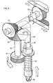
- Actuating assembly 24 further comprises a pinion 70 mounting on a drive shaft 72.
- Bevel gear 74 is also mounted on the drive shaft 72 on an end opposite pinion 70.
- Bevel gear 74 drivingly engages a matching bevel gear 76 which is mounted on a vertically extending shaft 78.
- Bearings 80, 82 are provided to journal mount shafts 72, 78, respectively.
- Bar 110 is pivotally mounted on cover 18 near the leading edge thereof.
- Bar 110 has a ramp 109 and an elevated surface 107 for receiving roller 98 of lock shaft 96 and urging the lock shaft 96 upwardly to the raised position and to unlock the actuating assembly 24.
- Bar 110 has a spring 111 extending between the trailing end and the cover 108.
- a shock absorber 113 also extends from the trailing end and the cover 108. The spring 111 and shock absorber 113 control the pivotal movement of the bar 110.
- a sleeve 112 is slidably mounted on bar 110 for travel in the direction of travel 14.
- a spring 114 extends between the sleeve 112 and bar 110 and urges the sleeve towards the leading edge of the cover 108.
- a shock absorber 116 is pivotally mounted at one end to the sleeve 112 and pivotally mounted at the opposite end to the cover 108.
- Sleeve 114 has an abutment 118 at the trailing end thereof.
- Sleeve 112 has an L-shaped flange 120 having a rack of teeth 122 which are complementary to and operatively engage the bevel gear 94. The leading edge of the rack of teeth 122 is slightly tapered to allow smooth engagement between the teeth 122 and bevel gear 94.
- Cover 108 has a stop 124 positioned near the trailing end of the cover 108. Bar 110 will rest against the stop 124 under the influence of spring 111. Stop 124 will also engage abutment 118 of sleeve 112 as the sleeve 112 is moved towards the trailing end which will cause the sleeve 112 and the rack of teeth 122 to pivot outwardly to disengage the rack of teeth 122 from the bevel gear 94.
- the fixture mounting assembly 26 comprises a plurality of U-shaped supports 126. Each of the supports 126 are mounted on one of the fixed arm 50 or movable arms 62.
- the paint wagon has seven mounting fixtures, six movable fixtures and one stationary fixture. It is apparent to those skilled in the art that any number of fixtures could be accommodated.
- Housing 104 shrouds the gear or operating components of the paint wagon 10 from paint over spray.
- cars 52, 54 and 56 are made from stainless steel in order to minimize damage from the paint and the requisite cleaning solvents needed to clean and remove over sprayed paint.
- the preferred shape of mounting arms 62 is as illustrated in Figure 2. The shape allows a further shroud to be placed over the channel 42 further minimizing the risk of paint being applied to the cars 52, 54 and 56.
- the paint wagon 10 of the present invention is selectively engaged to the conveyor 12.
- the paint wagon 10 will be pulled about in the direction of travel 14.
- the lock shaft 96 will be in the down or locked position, holding the fixture mounting assembly 26 in place in the contracted condition.
- the paint wagon 10 will encounter one of a desired number of actuating mechanisms 20.
- the roller 98 will engage the ramp 109 which will lift the lock shaft 96 upwardly, disengaging the bevel gear 94 of the actuating assembly 24.
- spur gear 94 will engage rack of teeth 122 which will cause rotation thereof in an expanding sense. Rotation of spur gear 94 will in turn rotate pinion 70, which in turn will cause outwardly movement of the racks 84, 86.
- the spring 111 will return the bar 110 and sleeve 112 back to a ready position in parallel to the direction of travel 14.
- the lock shaft 96 will fall off the trailing edge of the bar 110 allowing the lock shaft to move downwardly to the lowered position to re-engage the bevel gear 100 with the bevel gear 76, locking the actuating assembly 24 in place.
- an actuating mechanism 20 is mounted on the floor 16.
- the contracting actuating mechanism 20 is a mirror image of the mechanism shown in the Figures 7, 8, and 9.
- the rack of teeth 122 will be on the opposite side of the bar 110 and will rotation of the spur gear 94 in a contracting sense opposite the expanding sense.
- Rotation of the spur gear 94 in the contracting sense will cause rotation of the pinion 70 in the contracting sense.
- Pinion 70 will cause racks 84, 86 to move inwardly.
- Racks 84, 86 will move the outer cars 56 inwardly which will urge middle cars 54 inwardly and then inner cars 52 inwardly to the contracted position.
- Bars 68 will space the outer cars 56 from the middle cars 54 from the inner cars 52. By selecting the length of bars 68, a minimum spacing between supports 126 is determined.
- any number of actuating mechanisms 20 can be placed about the length of the conveyor 12 to expand and contract the paint wagon 10 as desired.
- the paint wagons 10 are contracted to turn comers and expanded for painting, mounting and dismounting parts to be painted onto and from the paint wagon 10.
- the actuating mechanisms 20 have a low profile minimizing risk of contact by fork lift trucks and workers. Additionally, actuating mechanisms 20 are mounted directly under the path of travel of the paint wagons 10 and therefore not in an area normally accessed by workers.
Landscapes
- Spray Control Apparatus (AREA)
- Automobile Manufacture Line, Endless Track Vehicle, Trailer (AREA)
Claims (14)
- Wagonnet de peinture (10), comprenant :caractérisé par :une base (22) ayant une pluralité de roues (28, 30) montées en relation de supportage vis-à-vis de celle-ci ;une tige descendante (32) montée en coulissement sur ladite base (22), ladite tige descendante (32) pouvant être sélectivement engagée avec un convoyeur (12) pour déplacer en translation ledit wagonnet de peinture (10) le long d'un trajet ;une pluralité de ferrures de montage (26) montées en coulissement, lesdites ferrures (26) étant mobiles entre une position contractée et une position en expansion,un ensemble d'actionnement (24) pour monter en coulissement lesdites ferrures de montage (26) sur ladite base (22), ledit ensemble d'actionnement (24) comprenant :un support longitudinal (38) monté sur ladite base (22),une pluralité de chariots (52, 54, 56) en engagement de coulissement avec ledit support longitudinal (38), chacun des chariots de ladite pluralité (52, 54, 56) ayant l'une desdites ferrures de montage (26) qui s'étend de lui-même, un pignon (70) monté en rotation ; etune première crémaillère (84) montée en coulissement avec ledit support longitudinal (38), ledit pignon (70) étant en engagement d'entraínement avec ladite première crémaillère (84), ladite première crémaillère (84) étant connectée à un chariot extérieur parmi lesdits chariots (52, 54, 56), ladite première crémaillère (84) comportant une pluralité de languettes (90, 92) s'étendant depuis elle-même et positionnées de manière à engager sélectivement des chariots intérieurs parmi lesdits chariots (52, 54, 56) pour déplacer lesdits chariots intérieurs vers l'extérieur et espacer automatiquement lesdits chariots (52, 54, 56), dans lequel la rotation dudit pignon (70) effectue ledit mouvement desdites ferrures de montage (26) entre la position contractée et la position en expansion.
- Wagonnet de peinture (10) selon la revendication 1, dans lequel chacun desdits chariots (52, 54, 56) comprend une barre positionnée pour écarter ladite pluralité de chariots (52, 54, 56) vis-à-vis d'un chariot adjacent lors du déplacement desdites ferrures de montage (26) à ladite position contractée.
- Wagonnet de peinture (10) selon la revendication 2, dans lequel ledit wagonnet de peinture (10) comprend encore une seconde crémaillère (86) montée en coulissement avec ledit support longitudinal (38), ledit pignon (70) étant en engagement d'entraínement avec ladite seconde crémaillère (86), ladite seconde crémaillère (86) étant connectée à un chariot extérieur parmi lesdits chariots (52, 54, 56), ledit second chariot (86) ayant une pluralité de languettes s'étendant depuis elle-même et positionnées de manière à engager sélectivement des chariots intérieurs parmi lesdits chariots (52, 54, 56) pour déplacer lesdits chariots intérieurs vers l'extérieur et espacer automatiquement lesdits chariots (52, 54, 56) lorsqu'elle se déplace à la condition en expansion.
- Wagonnet de peinture (10) selon la revendication 3, dans lequel ladite seconde crémaillère (86) s'étend dans une direction opposée a ladite première crémaillère (84).
- Wagonnet de peinture (10) selon la revendication 4, dans lequel ledit wagonnet de peinture (10) comprend une ferrure de montage fixe (26) positionnée entre des ferrures de montage (26) fonctionnellement en engagement avec ladite première crémaillère (84) et des ferrures de montage (26) fonctionnellement en engagement avec ladite seconde crémaillère (86).
- Wagonnet de peinture selon la revendication 5, dans lequel ledit ensemble d'actionnement comprend en outre une tige (78) s'étendant vers le bas et sur laquelle est monté un engrenage (94), ladite tige (78) engageant fonctionnellement ledit pignon (70), ledit engrenage (94) étant positionné de manière à engager une rangée de dents complémentaires fixées par rapport audit wagonnet de peinture (10) de telle manière que lorsque ledit wagonnet de peinture (10) se déplace en translation le long dudit trajet, ledit engrenage (94) tourne en entraínant la rotation dudit pignon (70).
- Wagonnet de peinture (10) selon la revendication 6, dans lequel ledit ensemble d'actionnement comprend en outre une tige de verrouillage (96) montée en coulissement dans la partie antérieure de ladite tige (78), ladite tige étant mobile entre une position basse et une position haute, ladite tige de verrouillage (96) engageant ladite tige (78) en empêchant sa rotation quand ladite tige de verrouillage (96) est dans ladite position basse, et ladite tige de verrouillage (96) se dégageant de ladite tige (78) quand ladite tige de verrouillage (96) est dans ladite position haute.
- Wagonnet de peinture (10) selon la revendication 7, dans lequel ledit wagonnet de peinture (10) comprend un boítier (104) pour protéger les composants fonctionnels dudit wagonnet de peinture (10) vis-à-vis des projections de peinture.
- Wagonnet de peinture.(10) selon la revendication 8, dans lequel ledit support longitudinal (38) est un tronçon en forme de C ayant un profilé allongé ouvert définissant un guide supérieur et un guide inférieur, et chacun desdits chariots comprend une pluralité de roues (28, 30) montées en rotation et engageant ledit guide supérieur et ledit guide inférieur.
- Wagonnet de peinture (10) selon la revendication 9, dans lequel ledit wagonnet de peinture (10) comprend au moins trois chariots et lesdits chariots intérieurs parmi lesdits chariots comprennent un chariot intérieur et un chariot central positionné entre ledit chariot extérieur parmi lesdits chariots (52, 54, 56) et ledit chariot intérieur, ledit chariot intérieur ayant une languette sur un bord d'attaque quand ledit chariot intérieur est en déplacement dans une direction en expansion, ladite languette du chariot intérieur engageant l'une de ladite pluralité de languettes sur une crémaillère respective, et ledit chariot central ayant une languette sur un bord de queue quand ledit chariot central est en déplacement dans une direction en expansion, ladite languette du chariot central engageant une autre de ladite pluralité de languettes sur une crémaillère respective.
- Wagonnet de peinture (10) selon la revendication 10, dans lequel ladite pluralité de languettes sur ladite crémaillère se projettent de manière orthogonale depuis celle-ci.
- Wagonnet de peinture (10) selon l'une quelconque des revendications précédentes, en combinaison avec un mécanisme d'actionnement monté le long dudit trajet, ledit ensemble d'actionnement engageant sélectivement ledit mécanisme d'actionnement tandis que ledit wagonnet de peinture circule le long dudit trajet, en effectuant à titre de réponse une rotation dudit pignon (70), et pour effectuer ledit mouvement desdites ferrures de montage entre la position contractée et la position en expansion.
- Combinaison selon la revendication 12, dans laquelle ledit mécanisme d'actionnement (20) comprend :un boítier ayant une fente qui s'étend vers le haut pour recevoir ladite tige descendante tandis que ledit wagonnet de peinture (10) circule devant ledit mécanisme d'actionnement,une barre à montage pivotant présentant une rampe et une surface élevée qui effectuent le mouvement de ladite tige de verrouillage entre ladite position basse et ladite position haute,un arrêt, etladite rangée de dents (122) étant montée en coulissement pour coopérer avec ladite barre, ladite rangée de dents (122) étant sollicitée vers un bord d'attaque dudit mécanisme d'actionnement (20), ladite barre étant sollicitée pour repousser ladite rangée de dents (122) en engagement avec ledit engrenage (94), ladite rangée de dents (122) étant capable de coulisser par rapport à ladite barre quand ledit engrenage (94) s'arrête de tourner jusqu'à ce que ladite rangée de dents (122) engage ledit arrêt, suite à quoi ledit arrêt fait pivoter ladite rangée de dents (122) hors de l'engagement avec ledit engrenage (94).
- Combinaison selon la revendication 13, comprenant en outre une série d'éléments d'actionnement positionnés le long dudit trajet pour effectuer alternativement un mouvement desdites ferrures de montage entre ladite position contractée et ladite position en expansion.
Applications Claiming Priority (3)
| Application Number | Priority Date | Filing Date | Title |
|---|---|---|---|
| US21088100P | 2000-06-09 | 2000-06-09 | |
| US210881P | 2000-06-09 | ||
| PCT/CA2001/000844 WO2001094026A1 (fr) | 2000-06-09 | 2001-06-11 | Wagonnet de peinture extensible avec mecanisme d'entrainement a cremaillere |
Publications (2)
| Publication Number | Publication Date |
|---|---|
| EP1286785A1 EP1286785A1 (fr) | 2003-03-05 |
| EP1286785B1 true EP1286785B1 (fr) | 2004-10-13 |
Family
ID=22784659
Family Applications (1)
| Application Number | Title | Priority Date | Filing Date |
|---|---|---|---|
| EP01949116A Expired - Lifetime EP1286785B1 (fr) | 2000-06-09 | 2001-06-11 | Wagonnet de peinture extensible avec mecanisme d'entrainement a cremaillere |
Country Status (7)
| Country | Link |
|---|---|
| US (1) | US6705233B2 (fr) |
| EP (1) | EP1286785B1 (fr) |
| AU (1) | AU2001270362A1 (fr) |
| CA (1) | CA2411932C (fr) |
| DE (1) | DE60106431T2 (fr) |
| MX (1) | MXPA02012135A (fr) |
| WO (1) | WO2001094026A1 (fr) |
Families Citing this family (7)
| Publication number | Priority date | Publication date | Assignee | Title |
|---|---|---|---|---|
| WO2007102773A1 (fr) * | 2006-03-08 | 2007-09-13 | Skanska Sverige Ab | Systeme de construction a dispositif de positionnement et procede de construction d'un batiment a etages |
| US10165860B2 (en) * | 2016-05-09 | 2019-01-01 | Whirlpool Corporation | Cosmetic door panel suspension and adjustment system for a built-in appliance |
| CN113171896B (zh) * | 2021-04-29 | 2022-12-23 | 浙江三荣门业有限公司 | 一种翻转组件及防火门表面静电喷涂装置 |
| CN113246049A (zh) * | 2021-07-15 | 2021-08-13 | 大连理工江苏研究院有限公司 | 一种具有定位功能的金属加工治具及定位方法 |
| US11857090B2 (en) | 2021-09-30 | 2024-01-02 | Darren Alonzo Harris | Art rack with dowels |
| CN117900066B (zh) * | 2024-03-19 | 2024-06-04 | 山东裕鸿阀门股份有限公司 | 一种阀门喷涂工艺及设备 |
| CN118558504B (zh) * | 2024-08-05 | 2024-10-15 | 兴化市纪宇塑业有限公司 | 一种五金制品表面喷漆装置 |
Family Cites Families (7)
| Publication number | Priority date | Publication date | Assignee | Title |
|---|---|---|---|---|
| DE3269347D1 (en) * | 1981-06-15 | 1986-04-03 | Fredenhagen Kg | Floor transportation system |
| SE8602154D0 (sv) * | 1986-05-13 | 1986-05-13 | Electrolux Const Ab | Forvaringssystem |
| US5249823A (en) * | 1992-10-09 | 1993-10-05 | E.B.S. Equipment Services, Inc. | Size variable cart |
| US5350162A (en) * | 1993-03-08 | 1994-09-27 | Cushing Meredith K | Apparatus for assembling reinforcing bar pier cages |
| US5497060A (en) * | 1993-06-21 | 1996-03-05 | Juergens, Iii; Albert M. | Positioning stage |
| US5772233A (en) | 1996-04-09 | 1998-06-30 | Decoma International Inc. | Expandable painting wagon |
| CA2324820C (fr) * | 2000-10-30 | 2004-05-04 | Clayton Dean Babchuk | Dispositif d'appui de piece |
-
2001
- 2001-06-11 US US10/297,797 patent/US6705233B2/en not_active Expired - Fee Related
- 2001-06-11 WO PCT/CA2001/000844 patent/WO2001094026A1/fr not_active Ceased
- 2001-06-11 MX MXPA02012135A patent/MXPA02012135A/es active IP Right Grant
- 2001-06-11 CA CA002411932A patent/CA2411932C/fr not_active Expired - Fee Related
- 2001-06-11 AU AU2001270362A patent/AU2001270362A1/en not_active Abandoned
- 2001-06-11 DE DE60106431T patent/DE60106431T2/de not_active Expired - Lifetime
- 2001-06-11 EP EP01949116A patent/EP1286785B1/fr not_active Expired - Lifetime
Also Published As
| Publication number | Publication date |
|---|---|
| US6705233B2 (en) | 2004-03-16 |
| CA2411932C (fr) | 2009-01-27 |
| AU2001270362A1 (en) | 2001-12-17 |
| DE60106431T2 (de) | 2006-02-02 |
| MXPA02012135A (es) | 2003-10-15 |
| CA2411932A1 (fr) | 2001-12-13 |
| DE60106431D1 (de) | 2004-11-18 |
| EP1286785A1 (fr) | 2003-03-05 |
| US20030136296A1 (en) | 2003-07-24 |
| WO2001094026A1 (fr) | 2001-12-13 |
Similar Documents
| Publication | Publication Date | Title |
|---|---|---|
| EP1079200B1 (fr) | Dispositif pyrotechnique de connexion et de retard | |
| US5791857A (en) | Automatic ladder lowering and storage device for use with an emergency vehicle | |
| US6247601B1 (en) | Glass pane handling assembly | |
| AU2018344764B2 (en) | A rack and apparatus for supporting wheels | |
| US6705233B2 (en) | Expandable painting wagon having a rack and pinion drive mechanism | |
| RU1838070C (ru) | Устройство дл сварки подсборок кузова автомобил | |
| EP3640145B1 (fr) | Guide latéral mobile intégré et ensemble de plateau à rouleaux pour système de gestion de cargaison | |
| US20220324390A1 (en) | Vehicle rack system | |
| US20080156589A1 (en) | Lifting Platform for the Maintenance and Repair of Light Vehicles | |
| JPH0352387B2 (fr) | ||
| EP4469331B1 (fr) | Chariot automoteur d'inspection du soubassement de véhicules ferroviaires, le chariot ayant un dispositif de positionnement intégré | |
| EP0442245A1 (fr) | Dispositif de verrouillage des roues d'un véhicule transporté par un wagon | |
| US6592319B2 (en) | Gate extension assembly for bed mounted rolling racks | |
| JP2968796B1 (ja) | 圧延機のロール組替装置 | |
| GB2298408A (en) | Mobile lifting system for rail vehicle bogies | |
| JPH10148039A (ja) | 伸縮可能な幌部を有する車庫装置及び自動車用幌装置 | |
| CN111153228A (zh) | 一种平移式驮背车装卸车的站场设备系统 | |
| EP0501935B1 (fr) | Appareil de manutention de véhicules automobiles des systèmes de garage à étages multiples | |
| US20220363484A1 (en) | Drop and slide out idler assembly | |
| CN108820076A (zh) | 一种简易高位轮胎快速安装工装 | |
| US3844222A (en) | Conveyor for wheeled vehicles | |
| CN211643907U (zh) | 一种平移式驮背车装卸车的站场设备系统 | |
| KR100470179B1 (ko) | 장비 상차 및 하차장치 | |
| JP3736923B2 (ja) | 機械式立体駐車場のターンテーブル旋回装置 | |
| RU2844186C1 (ru) | Устройство для установки, фиксации и извлечения запасного колеса |
Legal Events
| Date | Code | Title | Description |
|---|---|---|---|
| PUAI | Public reference made under article 153(3) epc to a published international application that has entered the european phase |
Free format text: ORIGINAL CODE: 0009012 |
|
| 17P | Request for examination filed |
Effective date: 20021211 |
|
| AK | Designated contracting states |
Kind code of ref document: A1 Designated state(s): AT BE CH CY DE DK ES FI FR GB GR IE IT LI LU MC NL PT SE TR |
|
| AX | Request for extension of the european patent |
Extension state: AL LT LV MK RO SI |
|
| GRAP | Despatch of communication of intention to grant a patent |
Free format text: ORIGINAL CODE: EPIDOSNIGR1 |
|
| RBV | Designated contracting states (corrected) |
Designated state(s): BE DE GB |
|
| GRAS | Grant fee paid |
Free format text: ORIGINAL CODE: EPIDOSNIGR3 |
|
| GRAA | (expected) grant |
Free format text: ORIGINAL CODE: 0009210 |
|
| AK | Designated contracting states |
Kind code of ref document: B1 Designated state(s): BE DE GB |
|
| REG | Reference to a national code |
Ref country code: GB Ref legal event code: FG4D |
|
| REG | Reference to a national code |
Ref country code: IE Ref legal event code: FG4D |
|
| REF | Corresponds to: |
Ref document number: 60106431 Country of ref document: DE Date of ref document: 20041118 Kind code of ref document: P |
|
| LTIE | Lt: invalidation of european patent or patent extension |
Effective date: 20041013 |
|
| PLBE | No opposition filed within time limit |
Free format text: ORIGINAL CODE: 0009261 |
|
| STAA | Information on the status of an ep patent application or granted ep patent |
Free format text: STATUS: NO OPPOSITION FILED WITHIN TIME LIMIT |
|
| 26N | No opposition filed |
Effective date: 20050714 |
|
| PGFP | Annual fee paid to national office [announced via postgrant information from national office to epo] |
Ref country code: DE Payment date: 20120607 Year of fee payment: 12 |
|
| PGFP | Annual fee paid to national office [announced via postgrant information from national office to epo] |
Ref country code: GB Payment date: 20120606 Year of fee payment: 12 |
|
| PGFP | Annual fee paid to national office [announced via postgrant information from national office to epo] |
Ref country code: BE Payment date: 20120620 Year of fee payment: 12 |
|
| BERE | Be: lapsed |
Owner name: *DECOMA INTERNATIONAL INC. Effective date: 20130630 |
|
| GBPC | Gb: european patent ceased through non-payment of renewal fee |
Effective date: 20130611 |
|
| REG | Reference to a national code |
Ref country code: DE Ref legal event code: R119 Ref document number: 60106431 Country of ref document: DE Effective date: 20140101 |
|
| PG25 | Lapsed in a contracting state [announced via postgrant information from national office to epo] |
Ref country code: BE Free format text: LAPSE BECAUSE OF NON-PAYMENT OF DUE FEES Effective date: 20130630 |
|
| PG25 | Lapsed in a contracting state [announced via postgrant information from national office to epo] |
Ref country code: DE Free format text: LAPSE BECAUSE OF NON-PAYMENT OF DUE FEES Effective date: 20140101 Ref country code: GB Free format text: LAPSE BECAUSE OF NON-PAYMENT OF DUE FEES Effective date: 20130611 |