EP1286826B1 - Filet en matiere plastique constitue d'un film etirable en matiere plastique, et dispositif et procede de fabrication d'un tel filet - Google Patents
Filet en matiere plastique constitue d'un film etirable en matiere plastique, et dispositif et procede de fabrication d'un tel filet Download PDFInfo
- Publication number
- EP1286826B1 EP1286826B1 EP01953966A EP01953966A EP1286826B1 EP 1286826 B1 EP1286826 B1 EP 1286826B1 EP 01953966 A EP01953966 A EP 01953966A EP 01953966 A EP01953966 A EP 01953966A EP 1286826 B1 EP1286826 B1 EP 1286826B1
- Authority
- EP
- European Patent Office
- Prior art keywords
- stretch film
- plastic
- roller
- plastic stretch
- main direction
- Prior art date
- Legal status (The legal status is an assumption and is not a legal conclusion. Google has not performed a legal analysis and makes no representation as to the accuracy of the status listed.)
- Expired - Lifetime
Links
Images



Classifications
-
- B—PERFORMING OPERATIONS; TRANSPORTING
- B29—WORKING OF PLASTICS; WORKING OF SUBSTANCES IN A PLASTIC STATE IN GENERAL
- B29D—PRODUCING PARTICULAR ARTICLES FROM PLASTICS OR FROM SUBSTANCES IN A PLASTIC STATE
- B29D28/00—Producing nets or the like, e.g. meshes, lattices
-
- B—PERFORMING OPERATIONS; TRANSPORTING
- B29—WORKING OF PLASTICS; WORKING OF SUBSTANCES IN A PLASTIC STATE IN GENERAL
- B29C—SHAPING OR JOINING OF PLASTICS; SHAPING OF MATERIAL IN A PLASTIC STATE, NOT OTHERWISE PROVIDED FOR; AFTER-TREATMENT OF THE SHAPED PRODUCTS, e.g. REPAIRING
- B29C55/00—Shaping by stretching, e.g. drawing through a die; Apparatus therefor
- B29C55/02—Shaping by stretching, e.g. drawing through a die; Apparatus therefor of plates or sheets
- B29C55/18—Shaping by stretching, e.g. drawing through a die; Apparatus therefor of plates or sheets by squeezing between surfaces, e.g. rollers
-
- Y—GENERAL TAGGING OF NEW TECHNOLOGICAL DEVELOPMENTS; GENERAL TAGGING OF CROSS-SECTIONAL TECHNOLOGIES SPANNING OVER SEVERAL SECTIONS OF THE IPC; TECHNICAL SUBJECTS COVERED BY FORMER USPC CROSS-REFERENCE ART COLLECTIONS [XRACs] AND DIGESTS
- Y10—TECHNICAL SUBJECTS COVERED BY FORMER USPC
- Y10T—TECHNICAL SUBJECTS COVERED BY FORMER US CLASSIFICATION
- Y10T428/00—Stock material or miscellaneous articles
- Y10T428/24—Structurally defined web or sheet [e.g., overall dimension, etc.]
- Y10T428/24273—Structurally defined web or sheet [e.g., overall dimension, etc.] including aperture
Definitions
- the invention relates to a plastic net of a plastic stretch film and for the production of suitable devices and methods.
- EP 820 856 A1 is a pre-stretched plastic stretch film known at the holes by a thermal irradiation process without touching the film and thus without foil waste, z. B. by punching, are generated.
- nets For other packaging purposes, nets have proven to be more suitable usually braided from single threads or narrow ribbons or knotted. The nets have only limited elasticity, which limits their suitability as packaging material. Besides, theirs Production consuming.
- WO 91/18735 A1 discloses the use of LLDPE polyethylene.
- the invention is based on the object, a simplified in the production Plastic net and a method for its production and for it specify appropriate devices.
- the object is achieved by a plastic net according to claim 1 solved.
- Devices for its production are independent Claims 5 and 7 defined.
- a method for producing the Plastic net results from claim 12
- Advantageous developments of the invention are defined in the dependent claims.
- LLDPE polyethylene existing plastic network has a variety arranged in columns and rows holes, wherein between each two holes a bridge is formed, the two are in one Main thread connecting threads and compared to the rest Regions of the plastic stretch film is additionally pre-stretched.
- a film web of a pre-stretched plastic stretch film by local action of heat on each hole with holes Provided.
- the resulting webs, which are transverse to the main direction extend the plastic stretch film are in a suitable Device pre-stretched to the width of the film and thus their utilization to enlarge. Then they will be in the main direction extending threads in another device transversely folded to to achieve the required strength per unit width of the plastic network.
- An apparatus for pre-stretching the webs has two rollers, wherein steel discs mounted on a first roller in a second roller existing recesses engages. Since the rollers touch and with a material of high Coefficient of friction coated, the plastic film can at a passage of the device held on the respective threads while the webs are stretched through the steel discs and thus pre-stretched become.
- An inventive device for transverse folding of the threads has two Roll pairs on, between which a forming area is provided against the plastic stretch film is stretched.
- the forming area points in a first section of guide rails over which the webs of the Plastic net can be moved while sliding the threads in the spaces between the guide rails on a guide plate slide.
- the guide rails go in Form ribs over, which are increasingly widening while exceeding their height the guide plate decreases. This will cause the between the ribs curled or laterally folded lateral threads.
- a cross-compression the threads does not take place. Rather, the film material a single thread forced to overlap in several layers to lay, whereby the transverse folds arise.
- Fig. 1 shows a schematic side view of the entire system for Producing a plastic network according to the invention.
- a perforating device 3 are in the plastic stretch film 2 by means of a produced known method holes. This is basically by mechanical Punching the plastic stretch film 2 possible. As better suited However, a thermal hole method has proven in which a plate with a variety of heated to at least 500 ° C tips on the Foil is applied. As soon as the tips touch the plastic stretch film 2, open at the relevant points holes in the film, at the Scope each forms a bead whose thickness is greater than that Thickness of the remaining plastic stretch film 2. The resulting accumulation of material at each of the holes allows the plastic stretch film 2 in the subsequent steps in addition to stretch, without that the material breaks down.
- FIG. 2 shows a plan view of a detail of the plastic stretch film 2 after leaving the punching device 3.
- holes 4 are in columns extending in a main direction 5 and arranged transversely thereto rows.
- Main direction 5 extending webs to be regarded as threads 6 are, while the transverse to the main direction 5 and the threads 6 connecting material parts are referred to as webs 7.
- webs 7 As shown in FIG. 2 can be seen, the transition between threads 6 and webs 7 is flowing.
- thread a hatched area is drawn, to the two also marked by hatched areas Ridges 7 are adjacent.
- threads 6 and webs 7 as subregions of the plastic stretch film 2 serves inter alia, the following explanation of Invention.
- the plastic stretch film 2 is after leaving the hole device 3rd by a known, consisting of a pair of rollers longitudinal stretching device 8 led.
- Vorrereckvortechnische 9 a device for pre-stretching the webs 7 (hereinafter Vorrereckvortechnisch 9 called).
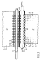
- the pre-stretching device 9 shown in a plan view in FIG. 3 has a first roller 10 and a second roller 11.
- the rolling elements 12 and steel discs 13 are placed on the first roller 10 .
- the rolling elements 12 and steel discs 13 may be integral with each other be connected or pushed as individual elements on the first roller 10 become.
- the number of steel disks 13 corresponds to the number of holes 4 in one Transverse row of the plastic stretch film 2.
- the distance between the steel discs 13 thus corresponds exactly to the respective spacing of the holes 4 in the transverse direction.
- the rolling elements 12 are coated on their radially outer side with rubber.
- the second roller 11 also has rolling bodies 15, which are either as Individual elements are attached to the second roller 11 or as a single piece.
- the rolling elements 15 form recesses 16, the number of the number of Steel discs 13 corresponds.
- the radial peripheral surfaces of the rolling elements 15 are also rubber layers 17 covered.
- the first roller 10 and the second roller 11 arranged such that their rubber layers 14, 17 and Thus, their rolling elements 12, 15 touch each other and roll against each other can. As a result, the steel discs 13 engage in the associated recesses 16 one.
- Fig. 3 also shows schematically the path of the plastic stretch film brought up 2 in plan view, as is apparent from Fig. 1.
- the Plastic stretch film 2 is so between the first roller 10 and the the second roller 11 passed that the threads 6 each of the rubber layers 14, 17 are held while the holes 4 and the intervening located webs 7 initially over the recesses 16 to lie come. With further rotation of the rollers 10, 11 pass through the holes. 4 and webs 7 in the sphere of action of the steel discs 13 and deep pressed into the recesses 16, as determined by the deformed Plastic stretch film 18 is shown in Fig. 3.
- the webs 7 are stretched, whereby the width of the entire Bandes of plastic stretch film 2 significantly increased.
- the width of the entire Bandes of plastic stretch film 2 significantly increased.
- the effect of broadening is shown schematically in FIG represented by the wider band 19 of the plastic stretch film 2.
- the plastic stretch film passes 2 in an inventive device for transverse folding of Threads 6 (hereinafter called cross-folding device 20).
- the already corresponding to a network plastic stretch film 2 can also be used as a finished end product.
- the plastic stretch film 2 after leaving the pre-stretching 9 directly over transport and drafting rollers and a later described Heating device 31 led to a reel for winding, without that the threads 6 are transversely folded.
- This end product "suitable intermediate product” already has good properties as a plastic net. Across from the actual end product after passing through the entire process it has the advantage of a larger film width of for example 75-80 cm.
- the Querfaltvorutter 20 consists of a first pair of rollers 21, a second pair of rollers 22 and an intermediate arranged Umform Scheme 23rd
- the first pair of rollers 21 is in the embodiment shown in Fig. 1 of the invention formed by the pre-stretching device 9.
- the Cross folding 20 work without the pre-stretching device 9 can, the special effects of pre-stretching device 9 are not absolutely necessary.
- Vorstreckvortechnisch 9 can for the Querfaltvortechnisch 20 a conventional pair of rollers are used.
- the first and the second roller pair 21, 22 are capable of the plastic stretch film 2 to stretch - if necessary also to stretch - and against the main direction 5, d.
- FIG. 1 shows the forming area 23 in side view
- FIG. 5 shows the forming area 23 in a plan view (seen from the left in FIG. 1)
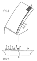
- FIG. 6 shows the forming area 23 in a spatial view.
- the forming area 23 has a curved guide plate 24, via which the plastic stretch film 2 is guided.
- the z. B. formed by a curved sheet can be, is in a first section 25 one of the number of webs 7 in the transverse direction corresponding number of guide rails 26 attached.
- the first section 25 takes the distance of the guide rails 26 from, as shown in Fig. 5 can be seen.
- FIG. 7 shows a schematic section through the deformation area 23 in FIG Direction of the arrow A in Fig. 1. Thereafter, each of the guide rails 26th formed by an elongated tube 27 which is connected to supports 28 on the Guide plate 24 is held.
- second section 29 go over the guide rails 26 in the form of ribs 30.
- the shaped ribs 30 are shown enlarged in FIG. 8.
- Each of the form ribs 30 points in a near the first section 25 located beginning region a height with respect to the guide plate 24, which is greater than that Width of the molding rib 30 is.
- the height of the molding rib 30 is smaller than its width. Accordingly, the gap between the molding ribs decreases 30, as shown in FIGS. 5 and 8 recognizable.
- the wedge-shaped ribs 30 from a Pipe or solid material produced and then attached to the guide plate 24 become.
- the plastic stretch film 2 is against the guide plate 24 by means of the roller pairs 21, 22 held tightly. It goes the plastic stretch film 2 on the guide rails 26 such that the threads 6 in the spaces between the guide rails 26, so in contact with the guide plate 24, while the Webs 7 arch over the guide rails 26, as can be seen also from Fig. 7 is.
- the Auffalt Bonus is after leaving the guide rail 26 through the Form ribs 30 reinforced even more.
- the webs 7 of the plastic stretch film. 2 are guided over the respective backs of the molding ribs 30, while the always located in the interstices of the form of ribs threads 6 be folded up more.
- the good adhesion of the material of the plastic stretch film 2 ensures that the thread 6 easily knit together leaves.
- the second pair of rollers 22 is used except for keeping tight and stretching the Plastic stretch film 2 as a squeegee to the folded To stabilize threads 6.
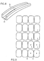
- the plastic net has the structure shown in FIG Structure, namely with stretched webs 7 and folded threads 6.
- the threads 6 have due to the caused by the transverse folding Material accumulation a very high strength, which for a tremendous stability the plastic net provides.
- the properties of the plastic net can be selected by selecting the Material thickness, by selecting the parameters of the above Method influenced network structure and in particular by the influence so-called "memory” effect in a variety of ways.
- the "memory” effect causes the stretch material after winding the plastic net around the object to be wrapped, so that the Plastic net firmly adheres to the object. This can be z.
- bales are wrapped on all sides by the plastic net, although neither the bales nor the winding device when winding turned Need to become.
- shrink tubing Her known, however, unsuitable for use in hay bales would.
Landscapes
- Engineering & Computer Science (AREA)
- Mechanical Engineering (AREA)
- Shaping By String And By Release Of Stress In Plastics And The Like (AREA)
- Shaping Of Tube Ends By Bending Or Straightening (AREA)
- Wrappers (AREA)
- Processing And Handling Of Plastics And Other Materials For Molding In General (AREA)
- Polishing Bodies And Polishing Tools (AREA)
- Registering, Tensioning, Guiding Webs, And Rollers Therefor (AREA)
- Materials For Medical Uses (AREA)
Claims (14)
- Filet en matière plastique composé d'un film étirable en matière plastique (2) préétiré, aveccaractérisé en ce que les fils (6) se composent de zones partielles du film étirable en matière plastique (2) qui sont pliées transversalement par rapport au sens principal.une multiplicité de trous (4) prévus dans le film étirable en matière plastique (2), qui sont disposés en colonnes s'étendant dans un sens principal et en rangées transversales par rapport à celui-ci ;des ponts (7) qui s'étendent entre les trous (4), transversalement par rapport au sens principal (5), et qui se composent du film étirable en matière plastique (2) ; etdes fils (6) qui s'étendent entre les trous (4) dans le sens principal (5) et qui se composent du film étirable en matière plastique (2) ;les ponts (7) étant préétirés transversalement par rapport au sens principal,
- Filet en matière plastique selon la revendication 1, caractérisé en ce que les trous (4) sont réalisés dans le film étirable en matière plastique (2) à l'aide d'un procédé thermique.
- Filet en matière plastique selon la revendication 2, caractérisé en ce que les trous (4), après avoir été réalisés et avant la suite du traitement, sont entourés par un renflement d'une épaisseur qui est supérieure à celle du film étirable en matière plastique, ce qui forme une accumulation de matière autour de chaque trou.
- Filet en matière plastique selon l'une des revendications 1 à 3, caractérisé en ce que le film étirable en matière plastique (2) se compose de polyéthylène LLDPE.
- Dispositif (9) pour fabriquer un filet en matière plastique, destiné à préétirer en continu transversalement par rapport à un sens principal (5) des zones partielles, s'étendant dans ce sens principal (5), d'un film étirable en matière plastique (2) qui traverse le dispositif, comprenant un premier rouleau (10) et un second rouleau (11) parallèle à celui-ci, étant précisécaractérisé en ce queque le premier rouleau (10) comprend au moins un nombre de plaques métalliques (13), espacées selon l'écartement desdites zones partielles, correspondant au nombre de zones partielles ;que le second rouleau (11) comprend un nombre de creux annulaires (16), espacés suivant l'écartement desdites plaques métalliques (13), correspondant au nombre de plaques métalliques (13) ;que le premier rouleau (10) et le second rouleau (11) sont espacés de telle sorte que chaque plaque métallique (13) du premier rouleau (10) pénètre dans un creux (16) du second rouleau (11) ;et que le film étirable en matière plastique (2) est apte à passer entre les deux rouleaux (10, 11) de telle sorte qu'une zone partielle à préétirer puisse passer tangentiellement entre une plaque métallique (13) et un creux correspondant (16) ;sur le premier rouleau (10), les zones de rouleau (12) situées près des plaques métalliques (13) sont revêtues d'une matière (14) à coefficient de frottement élevé ; et/ou en ce quesur le second rouleau (11), les zones de rouleau (15) situées près des creux annulaires (16) sont revêtues d'une matière (17) à coefficient de frottement élevé.
- Dispositif selon la revendication 5, caractérisé en ce que les zones de rouleau respectives (12, 15) des premier (10) et second (11) rouleaux sont revêtues des matières respectives (14, 17) et sont disposées de telle sorte que lesdites zones de rouleau (12, 15) revêtues de la matière (14, 17) se touchent et roulent l'une sur l'autre.
- Dispositif (20) pour fabriquer un filet en matière plastique, destiné au pliage transversal en continu de fils (6) s'étendant dans un sens principal (5) d'un film étirable en matière plastique (2) qui traverse le dispositif et qui présente une multiplicité de trous (4) disposés en rangées et en colonnes s'étendant dans le sens principal (5), comprenantétant préciséune première paire de rouleaux (21) et une seconde paire de rouleaux (22) qui tendent et transportent le film étirable en matière plastique (2) dans le sens principal (5) ;une zone de déformation courbe (23) disposée entre les première et seconde paires de rouleaux (21, 22) ;que les première et seconde paires de rouleaux (21, 22) et la zone de déformation (23) sont disposées les unes par rapport aux autres de telle sorte que le film étirable en matière plastique (2) puisse être tendu contre la zone de déformation (23) ;que la zone de déformation (23) présente une plaque de guidage (24) courbée dans le sens principal (5) ;qu'il est prévu sur la plaque de guidage (24), dans une première section (25), plusieurs rails de guidage (26) qui s'étendent sensiblement dans le sens principal (5) ;qu'il est prévu sur la plaque de guidage (24), dans une seconde section (29), plusieurs nervures de formage (30) qui font suite aux rails de guidage (26) ;que chacune des nervures de formage (30) présente dans une zone initiale proche de la première section (25) une hauteur par rapport à la plaque de guidage (24) qui est supérieure à une largeur de la nervure de formage (30), et que cette hauteur va en diminuant de manière continue, suivant la seconde section (29), vers la seconde paire de rouleaux (22), tandis que la largeur augmente, jusqu'à ce que la hauteur de ladite nervure (30) soit inférieure à sa largeur, près de la seconde paire de rouleaux (22).
- Dispositif selon la revendication 7, caractérisé en ce que l'écartement des rails de guidage (26) va en diminuant dans le sens de la première section (25).
- Dispositif selon la revendication 7 ou 8, caractérisé en ce que les rails de guidage (26) sont définis par plusieurs supports (28) qui sont fixés sur la plaque de guidage (24) et qui portent un corps de guidage (27).
- Dispositif selon la revendication 9, caractérisé en ce que le corps de guidage (27) peut être fabriqué à partir d'une matière brute.
- Dispositif selon l'une des revendications 7 à 10, caractérisé en ce que le film étirable en matière plastique (2) est apte à passer sur la zone de déformation (23) de telle sorte que les fils (6) glissent sur la plaque de guidage (24) et que les ponts (7) qui relient les fils (6) glissent sur les rails de guidage (26) et sur les nervures de formage (30).
- Procédé pour fabriquer un filet en matière plastique (2) selon l'une des revendications 1 à 4, comprenant les étapes consistant à :préparer une bande de film à partir d'un film étirable en matière plastique (2) préétiré ;faire des trous (4) dans le film étirable en matière plastique (2) grâce à une action thermique locale pour chaque trou (4) ;préétirer les ponts (7) ;plier transversalement les fils (6).
- Procédé selon la revendication 12, caractérisé par les étapes suivantes :pincement des fils (6) pliés transversalement, à l'aide d'une paire de rouleaux presseurs (22) ;passage du film étirable en matière plastique (2) par un dispositif chauffant (31).
- Procédé selon la revendication 12 ou 13, caractérisé en ce que le film étirable en matière plastique (2) est étiré dans le sens principal après la réalisation des trous (4) et avant le préétirage des ponts (7).
Applications Claiming Priority (3)
| Application Number | Priority Date | Filing Date | Title |
|---|---|---|---|
| DE10027527A DE10027527A1 (de) | 2000-06-02 | 2000-06-02 | Kunststoffnetz aus Kunststoffstreckfolie sowie Vorrichtung und Verfahren zu seiner Herstellung |
| DE10027527 | 2000-06-02 | ||
| PCT/EP2001/006164 WO2001091997A1 (fr) | 2000-06-02 | 2001-05-30 | Filet en matiere plastique constitue d'un film etirable en matiere plastique, et dispositif et procede de fabrication d'un tel filet |
Publications (2)
| Publication Number | Publication Date |
|---|---|
| EP1286826A1 EP1286826A1 (fr) | 2003-03-05 |
| EP1286826B1 true EP1286826B1 (fr) | 2004-03-17 |
Family
ID=7644564
Family Applications (1)
| Application Number | Title | Priority Date | Filing Date |
|---|---|---|---|
| EP01953966A Expired - Lifetime EP1286826B1 (fr) | 2000-06-02 | 2001-05-30 | Filet en matiere plastique constitue d'un film etirable en matiere plastique, et dispositif et procede de fabrication d'un tel filet |
Country Status (10)
| Country | Link |
|---|---|
| US (1) | US20030185926A1 (fr) |
| EP (1) | EP1286826B1 (fr) |
| AT (1) | ATE261810T1 (fr) |
| AU (1) | AU767381B2 (fr) |
| DE (3) | DE10027527A1 (fr) |
| DK (1) | DK1286826T3 (fr) |
| ES (1) | ES2215921T3 (fr) |
| IL (1) | IL153186A0 (fr) |
| PT (1) | PT1286826E (fr) |
| WO (1) | WO2001091997A1 (fr) |
Families Citing this family (5)
| Publication number | Priority date | Publication date | Assignee | Title |
|---|---|---|---|---|
| DE10201480B4 (de) * | 2002-01-16 | 2005-08-11 | Mega Plast S.A., Heraklion | Stretchfolie |
| DE10310814A1 (de) * | 2003-03-12 | 2004-09-23 | Mega Plast S.A., Heraklion | Kunststoffstreckfolie, Kunststoffnetz daraus und Verfahren zu deren Herstellung |
| US8053055B2 (en) | 2004-07-16 | 2011-11-08 | Megaplast S.A. | Stretch film |
| GB202108809D0 (en) | 2021-06-18 | 2021-08-04 | Mega Plast Ind Exporting S A | Improved film |
| CN114161692B (zh) * | 2021-12-31 | 2024-09-20 | 绍兴耐特塑胶有限公司 | 一种用于拉伸网的水浴拉伸机 |
Family Cites Families (6)
| Publication number | Priority date | Publication date | Assignee | Title |
|---|---|---|---|---|
| GB1546765A (en) * | 1975-05-23 | 1979-05-31 | Mercer Ltd F B | Stretching webs of sheet material |
| US4087225A (en) * | 1976-11-22 | 1978-05-02 | Papco Tool Corporation | Apparatus for flaring plastic tubing |
| NO152611C (no) * | 1978-10-16 | 1985-10-23 | Plg Res | Plastnettkonstruksjon, fremgangsmaate til dens fremstilling og anvendelse av konstruksjonen |
| US4389315A (en) * | 1981-07-24 | 1983-06-21 | Frank Crocket | Filter device with permeable corrugated grid panel |
| CH682381A5 (de) * | 1990-06-07 | 1993-09-15 | Breveteam Sa | Verfahren zur Herstellung einer Oeffnungen aufweisenden Kunststoff-Folie. |
| SI0820856T1 (en) * | 1996-07-26 | 2001-02-28 | Harilaos Kavvadias | Perforated pre-streched strech film for pallet wrapping |
-
2000
- 2000-06-02 DE DE10027527A patent/DE10027527A1/de not_active Withdrawn
-
2001
- 2001-05-30 AU AU76353/01A patent/AU767381B2/en not_active Ceased
- 2001-05-30 DE DE50101714T patent/DE50101714D1/de not_active Expired - Fee Related
- 2001-05-30 DE DE20109042U patent/DE20109042U1/de not_active Expired - Lifetime
- 2001-05-30 US US10/297,151 patent/US20030185926A1/en not_active Abandoned
- 2001-05-30 IL IL15318601A patent/IL153186A0/xx not_active IP Right Cessation
- 2001-05-30 EP EP01953966A patent/EP1286826B1/fr not_active Expired - Lifetime
- 2001-05-30 WO PCT/EP2001/006164 patent/WO2001091997A1/fr not_active Ceased
- 2001-05-30 DK DK01953966T patent/DK1286826T3/da active
- 2001-05-30 PT PT01953966T patent/PT1286826E/pt unknown
- 2001-05-30 AT AT01953966T patent/ATE261810T1/de not_active IP Right Cessation
- 2001-05-30 ES ES01953966T patent/ES2215921T3/es not_active Expired - Lifetime
Also Published As
| Publication number | Publication date |
|---|---|
| DE50101714D1 (de) | 2004-04-22 |
| WO2001091997B1 (fr) | 2002-03-21 |
| PT1286826E (pt) | 2004-08-31 |
| AU7635301A (en) | 2001-12-11 |
| DE10027527A1 (de) | 2001-12-20 |
| AU767381B2 (en) | 2003-11-06 |
| WO2001091997A1 (fr) | 2001-12-06 |
| DK1286826T3 (da) | 2004-04-13 |
| ATE261810T1 (de) | 2004-04-15 |
| US20030185926A1 (en) | 2003-10-02 |
| ES2215921T3 (es) | 2004-10-16 |
| DE20109042U1 (de) | 2001-10-25 |
| EP1286826A1 (fr) | 2003-03-05 |
| IL153186A0 (en) | 2003-06-24 |
Similar Documents
| Publication | Publication Date | Title |
|---|---|---|
| DE69013581T2 (de) | Verfahren und einrichtung für die ununterbrochene herstellung absorbierender körper. | |
| DE69320789T2 (de) | Laminierte filme | |
| DE2702221C3 (de) | Verfahren zum Herstellen eines orientierten Kunststoffnetzes | |
| DE3508941C2 (fr) | ||
| DE69210403T2 (de) | Verfahren und Vorrichtung zum Herstellen einer Membrane oder einer Folie zum Überziehen von Damenbinden oder Leinentückern oder für Filtersysteme oder dergleichen | |
| DE10007614B4 (de) | Streckfolie und Verfahren zur Herstellung einer Streckfolie | |
| DE2657695C3 (de) | Folienschlauch zur Bewässerung sowie Verfahren zu dessen Herstellung | |
| DE102013102813B4 (de) | Abstandsgewirke sowie Verfahren zur Herstellung eines Abstandsgewirkeabschnitts | |
| DE4123715C2 (de) | Verfahren zur Herstellung eines netzartigen ungewebten Textilstoffes | |
| DE69514112T2 (de) | Gummibandkette, verfahren und vorrichtung zu deren herstellung, sowie verfahren und vorrichtung für die zufuhr der gummibänder zu einer behandlungsvorrichtung | |
| DE1296780B (de) | Verfahren zum Herstellen eines gewebeaehnlichen Netzes aus einer aus thermoplastischem Kunststoff bestehenden Folie | |
| DE7328881U (de) | Netz aus polymeren werkstoffen | |
| EP3542648B1 (fr) | Dispositif et procédé de fabrication d'un boudin d'une matière en bande | |
| EP0350732B1 (fr) | Câble formé, élité | |
| DE1479628C3 (de) | Gittermatenal aus einem Film einer thermoplastischen Masse und Vor richtung zu seiner Herstellung | |
| DE2400941C2 (de) | Folie aus thermoplastischem Werkstoff zum Herstellen netzartiger Bahnen | |
| DE2409704A1 (de) | Verfahren und vorrichtung zur herstellung eines netzartigen gebildes aus ungewebten fasern | |
| EP0332907B1 (fr) | Garnissage pour le traitement de liquides et procédé pour sa fabrication | |
| DE2445255B2 (de) | Verfahren und Vorrichtung zum Herstellen einer Bahn aus Kunststoffsacken | |
| EP0891698A2 (fr) | Filet pour balles rondes | |
| DE10310814A1 (de) | Kunststoffstreckfolie, Kunststoffnetz daraus und Verfahren zu deren Herstellung | |
| DE1660223C3 (de) | Verfahren zur Herstellung endloser fadenartiger Gebilde mit thermoplastischen Kunststoffen | |
| DE102019116263A1 (de) | Einrichtung mit einer Mehrfach-Strangbildungsvorrichtung und Verfahren der Tabak verarbeitenden Industrie | |
| EP1286826A1 (fr) | Filet en matiere plastique constitue d'un film etirable en matiere plastique, et dispositif et procede de fabrication d'un tel filet | |
| WO2015185278A1 (fr) | Procédé de fabrication d'une toile de machine à papier |
Legal Events
| Date | Code | Title | Description |
|---|---|---|---|
| PUAI | Public reference made under article 153(3) epc to a published international application that has entered the european phase |
Free format text: ORIGINAL CODE: 0009012 |
|
| 17P | Request for examination filed |
Effective date: 20021107 |
|
| AK | Designated contracting states |
Kind code of ref document: A1 Designated state(s): AT BE CH CY DE DK ES FI FR GB GR IE IT LI LU MC NL PT SE TR Designated state(s): AT BE CH CY DE DK ES FI FR GB GR IE IT LI LU MC NL PT SE TR |
|
| GRAP | Despatch of communication of intention to grant a patent |
Free format text: ORIGINAL CODE: EPIDOSNIGR1 |
|
| GRAS | Grant fee paid |
Free format text: ORIGINAL CODE: EPIDOSNIGR3 |
|
| GRAA | (expected) grant |
Free format text: ORIGINAL CODE: 0009210 |
|
| AK | Designated contracting states |
Kind code of ref document: B1 Designated state(s): AT BE CH CY DE DK ES FI FR GB GR IE IT LI LU MC NL PT SE TR |
|
| PG25 | Lapsed in a contracting state [announced via postgrant information from national office to epo] |
Ref country code: TR Free format text: LAPSE BECAUSE OF FAILURE TO SUBMIT A TRANSLATION OF THE DESCRIPTION OR TO PAY THE FEE WITHIN THE PRESCRIBED TIME-LIMIT Effective date: 20040317 Ref country code: IE Free format text: LAPSE BECAUSE OF FAILURE TO SUBMIT A TRANSLATION OF THE DESCRIPTION OR TO PAY THE FEE WITHIN THE PRESCRIBED TIME-LIMIT Effective date: 20040317 Ref country code: FI Free format text: LAPSE BECAUSE OF FAILURE TO SUBMIT A TRANSLATION OF THE DESCRIPTION OR TO PAY THE FEE WITHIN THE PRESCRIBED TIME-LIMIT Effective date: 20040317 Ref country code: CY Free format text: LAPSE BECAUSE OF FAILURE TO SUBMIT A TRANSLATION OF THE DESCRIPTION OR TO PAY THE FEE WITHIN THE PRESCRIBED TIME-LIMIT Effective date: 20040317 |
|
| REG | Reference to a national code |
Ref country code: GB Ref legal event code: FG4D Free format text: NOT ENGLISH |
|
| REG | Reference to a national code |
Ref country code: CH Ref legal event code: EP |
|
| GBT | Gb: translation of ep patent filed (gb section 77(6)(a)/1977) |
Effective date: 20040317 |
|
| REG | Reference to a national code |
Ref country code: DK Ref legal event code: T3 |
|
| REG | Reference to a national code |
Ref country code: IE Ref legal event code: FG4D Free format text: GERMAN |
|
| REF | Corresponds to: |
Ref document number: 50101714 Country of ref document: DE Date of ref document: 20040422 Kind code of ref document: P |
|
| REG | Reference to a national code |
Ref country code: GR Ref legal event code: EP Ref document number: 20040401298 Country of ref document: GR |
|
| PG25 | Lapsed in a contracting state [announced via postgrant information from national office to epo] |
Ref country code: LU Free format text: LAPSE BECAUSE OF NON-PAYMENT OF DUE FEES Effective date: 20040530 |
|
| PG25 | Lapsed in a contracting state [announced via postgrant information from national office to epo] |
Ref country code: MC Free format text: LAPSE BECAUSE OF NON-PAYMENT OF DUE FEES Effective date: 20040531 |
|
| PG25 | Lapsed in a contracting state [announced via postgrant information from national office to epo] |
Ref country code: SE Free format text: LAPSE BECAUSE OF FAILURE TO SUBMIT A TRANSLATION OF THE DESCRIPTION OR TO PAY THE FEE WITHIN THE PRESCRIBED TIME-LIMIT Effective date: 20040617 |
|
| REG | Reference to a national code |
Ref country code: PT Ref legal event code: SC4A Free format text: AVAILABILITY OF NATIONAL TRANSLATION Effective date: 20040616 |
|
| REG | Reference to a national code |
Ref country code: ES Ref legal event code: FG2A Ref document number: 2215921 Country of ref document: ES Kind code of ref document: T3 |
|
| REG | Reference to a national code |
Ref country code: IE Ref legal event code: FD4D |
|
| ET | Fr: translation filed | ||
| PLBE | No opposition filed within time limit |
Free format text: ORIGINAL CODE: 0009261 |
|
| STAA | Information on the status of an ep patent application or granted ep patent |
Free format text: STATUS: NO OPPOSITION FILED WITHIN TIME LIMIT |
|
| 26N | No opposition filed |
Effective date: 20041220 |
|
| PGFP | Annual fee paid to national office [announced via postgrant information from national office to epo] |
Ref country code: AT Payment date: 20050421 Year of fee payment: 5 |
|
| PGFP | Annual fee paid to national office [announced via postgrant information from national office to epo] |
Ref country code: NL Payment date: 20050518 Year of fee payment: 5 |
|
| PGFP | Annual fee paid to national office [announced via postgrant information from national office to epo] |
Ref country code: GB Payment date: 20050519 Year of fee payment: 5 Ref country code: FR Payment date: 20050519 Year of fee payment: 5 |
|
| PGFP | Annual fee paid to national office [announced via postgrant information from national office to epo] |
Ref country code: BE Payment date: 20050523 Year of fee payment: 5 |
|
| PGFP | Annual fee paid to national office [announced via postgrant information from national office to epo] |
Ref country code: GR Payment date: 20050524 Year of fee payment: 5 |
|
| PGFP | Annual fee paid to national office [announced via postgrant information from national office to epo] |
Ref country code: DK Payment date: 20050525 Year of fee payment: 5 |
|
| PGFP | Annual fee paid to national office [announced via postgrant information from national office to epo] |
Ref country code: PT Payment date: 20050530 Year of fee payment: 5 Ref country code: DE Payment date: 20050530 Year of fee payment: 5 |
|
| PG25 | Lapsed in a contracting state [announced via postgrant information from national office to epo] |
Ref country code: LI Free format text: LAPSE BECAUSE OF NON-PAYMENT OF DUE FEES Effective date: 20050531 Ref country code: CH Free format text: LAPSE BECAUSE OF NON-PAYMENT OF DUE FEES Effective date: 20050531 |
|
| PGFP | Annual fee paid to national office [announced via postgrant information from national office to epo] |
Ref country code: ES Payment date: 20050531 Year of fee payment: 5 |
|
| REG | Reference to a national code |
Ref country code: CH Ref legal event code: PL |
|
| PG25 | Lapsed in a contracting state [announced via postgrant information from national office to epo] |
Ref country code: GB Free format text: LAPSE BECAUSE OF NON-PAYMENT OF DUE FEES Effective date: 20060530 Ref country code: AT Free format text: LAPSE BECAUSE OF NON-PAYMENT OF DUE FEES Effective date: 20060530 |
|
| PG25 | Lapsed in a contracting state [announced via postgrant information from national office to epo] |
Ref country code: ES Free format text: LAPSE BECAUSE OF NON-PAYMENT OF DUE FEES Effective date: 20060531 Ref country code: DK Free format text: LAPSE BECAUSE OF NON-PAYMENT OF DUE FEES Effective date: 20060531 Ref country code: BE Free format text: LAPSE BECAUSE OF NON-PAYMENT OF DUE FEES Effective date: 20060531 |
|
| PGFP | Annual fee paid to national office [announced via postgrant information from national office to epo] |
Ref country code: IT Payment date: 20060531 Year of fee payment: 6 |
|
| PG25 | Lapsed in a contracting state [announced via postgrant information from national office to epo] |
Ref country code: PT Free format text: LAPSE BECAUSE OF NON-PAYMENT OF DUE FEES Effective date: 20061130 |
|
| PG25 | Lapsed in a contracting state [announced via postgrant information from national office to epo] |
Ref country code: NL Free format text: LAPSE BECAUSE OF NON-PAYMENT OF DUE FEES Effective date: 20061201 Ref country code: DE Free format text: LAPSE BECAUSE OF NON-PAYMENT OF DUE FEES Effective date: 20061201 |
|
| REG | Reference to a national code |
Ref country code: DK Ref legal event code: EBP |
|
| GBPC | Gb: european patent ceased through non-payment of renewal fee |
Effective date: 20060530 |
|
| REG | Reference to a national code |
Ref country code: PT Ref legal event code: MM4A Free format text: LAPSE DUE TO NON-PAYMENT OF FEES Effective date: 20061130 |
|
| NLV4 | Nl: lapsed or anulled due to non-payment of the annual fee |
Effective date: 20061201 |
|
| REG | Reference to a national code |
Ref country code: FR Ref legal event code: ST Effective date: 20070131 |
|
| REG | Reference to a national code |
Ref country code: ES Ref legal event code: FD2A Effective date: 20060531 |
|
| BERE | Be: lapsed |
Owner name: S.A. *MEGA PLAST Effective date: 20060531 |
|
| PG25 | Lapsed in a contracting state [announced via postgrant information from national office to epo] |
Ref country code: FR Free format text: LAPSE BECAUSE OF NON-PAYMENT OF DUE FEES Effective date: 20060531 |
|
| PG25 | Lapsed in a contracting state [announced via postgrant information from national office to epo] |
Ref country code: GR Free format text: LAPSE BECAUSE OF NON-PAYMENT OF DUE FEES Effective date: 20061205 |
|
| PG25 | Lapsed in a contracting state [announced via postgrant information from national office to epo] |
Ref country code: IT Free format text: LAPSE BECAUSE OF NON-PAYMENT OF DUE FEES Effective date: 20070530 |