EP1286897B1 - Verfahren und vorrichtung zum mischen von komponenten mit hilfe einer gasdurchlässigen schicht - Google Patents
Verfahren und vorrichtung zum mischen von komponenten mit hilfe einer gasdurchlässigen schicht Download PDFInfo
- Publication number
- EP1286897B1 EP1286897B1 EP01918670A EP01918670A EP1286897B1 EP 1286897 B1 EP1286897 B1 EP 1286897B1 EP 01918670 A EP01918670 A EP 01918670A EP 01918670 A EP01918670 A EP 01918670A EP 1286897 B1 EP1286897 B1 EP 1286897B1
- Authority
- EP
- European Patent Office
- Prior art keywords
- container
- compartment
- liquid component
- vacuum source
- barrier
- Prior art date
- Legal status (The legal status is an assumption and is not a legal conclusion. Google has not performed a legal analysis and makes no representation as to the accuracy of the status listed.)
- Expired - Lifetime
Links
- 230000004888 barrier function Effects 0.000 title claims abstract description 67
- 238000000034 method Methods 0.000 title claims abstract description 10
- 150000001875 compounds Chemical class 0.000 title claims abstract description 8
- 239000007788 liquid Substances 0.000 claims abstract description 85
- 239000000843 powder Substances 0.000 claims abstract description 27
- 230000007246 mechanism Effects 0.000 claims abstract description 20
- 230000001010 compromised effect Effects 0.000 claims abstract description 11
- 239000012530 fluid Substances 0.000 claims abstract description 11
- 238000004891 communication Methods 0.000 claims abstract description 10
- 230000008595 infiltration Effects 0.000 claims abstract description 8
- 238000001764 infiltration Methods 0.000 claims abstract description 8
- 239000002639 bone cement Substances 0.000 claims description 33
- 239000000463 material Substances 0.000 claims description 28
- 230000014759 maintenance of location Effects 0.000 claims description 25
- 239000000178 monomer Substances 0.000 claims description 16
- 238000004806 packaging method and process Methods 0.000 claims description 12
- 239000011148 porous material Substances 0.000 claims description 10
- 230000035515 penetration Effects 0.000 claims description 7
- 238000009736 wetting Methods 0.000 claims description 3
- NIXOWILDQLNWCW-UHFFFAOYSA-N acrylic acid group Chemical group C(C=C)(=O)O NIXOWILDQLNWCW-UHFFFAOYSA-N 0.000 claims description 2
- 229920000058 polyacrylate Polymers 0.000 claims description 2
- 239000012528 membrane Substances 0.000 claims 8
- 230000005540 biological transmission Effects 0.000 claims 1
- 230000008878 coupling Effects 0.000 claims 1
- 238000010168 coupling process Methods 0.000 claims 1
- 238000005859 coupling reaction Methods 0.000 claims 1
- 229920000295 expanded polytetrafluoroethylene Polymers 0.000 claims 1
- 229920000642 polymer Polymers 0.000 description 12
- 239000002245 particle Substances 0.000 description 4
- VVQNEPGJFQJSBK-UHFFFAOYSA-N Methyl methacrylate Chemical compound COC(=O)C(C)=C VVQNEPGJFQJSBK-UHFFFAOYSA-N 0.000 description 3
- 238000010276 construction Methods 0.000 description 3
- 239000007787 solid Substances 0.000 description 3
- 239000004698 Polyethylene Substances 0.000 description 2
- PPBRXRYQALVLMV-UHFFFAOYSA-N Styrene Chemical compound C=CC1=CC=CC=C1 PPBRXRYQALVLMV-UHFFFAOYSA-N 0.000 description 2
- 239000000654 additive Substances 0.000 description 2
- TZCXTZWJZNENPQ-UHFFFAOYSA-L barium sulfate Chemical compound [Ba+2].[O-]S([O-])(=O)=O TZCXTZWJZNENPQ-UHFFFAOYSA-L 0.000 description 2
- 210000000988 bone and bone Anatomy 0.000 description 2
- 239000000316 bone substitute Substances 0.000 description 2
- 239000007943 implant Substances 0.000 description 2
- 238000004519 manufacturing process Methods 0.000 description 2
- -1 polyethylene Polymers 0.000 description 2
- 229920000573 polyethylene Polymers 0.000 description 2
- 230000008569 process Effects 0.000 description 2
- 239000004342 Benzoyl peroxide Substances 0.000 description 1
- OMPJBNCRMGITSC-UHFFFAOYSA-N Benzoylperoxide Chemical compound C=1C=CC=CC=1C(=O)OOC(=O)C1=CC=CC=C1 OMPJBNCRMGITSC-UHFFFAOYSA-N 0.000 description 1
- 229920000742 Cotton Polymers 0.000 description 1
- 229920000544 Gore-Tex Polymers 0.000 description 1
- 230000004913 activation Effects 0.000 description 1
- 150000001412 amines Chemical class 0.000 description 1
- 239000003242 anti bacterial agent Substances 0.000 description 1
- 238000013459 approach Methods 0.000 description 1
- 235000019400 benzoyl peroxide Nutrition 0.000 description 1
- 230000003115 biocidal effect Effects 0.000 description 1
- 230000015572 biosynthetic process Effects 0.000 description 1
- 239000004568 cement Substances 0.000 description 1
- 239000003086 colorant Substances 0.000 description 1
- 229940039231 contrast media Drugs 0.000 description 1
- 239000002872 contrast media Substances 0.000 description 1
- 229920001577 copolymer Polymers 0.000 description 1
- 238000005520 cutting process Methods 0.000 description 1
- 230000007547 defect Effects 0.000 description 1
- 230000005786 degenerative changes Effects 0.000 description 1
- 201000010099 disease Diseases 0.000 description 1
- 208000037265 diseases, disorders, signs and symptoms Diseases 0.000 description 1
- 230000003116 impacting effect Effects 0.000 description 1
- 230000006872 improvement Effects 0.000 description 1
- 238000011065 in-situ storage Methods 0.000 description 1
- 208000014674 injury Diseases 0.000 description 1
- 230000002427 irreversible effect Effects 0.000 description 1
- 238000004898 kneading Methods 0.000 description 1
- 239000000203 mixture Substances 0.000 description 1
- 238000012986 modification Methods 0.000 description 1
- 230000004048 modification Effects 0.000 description 1
- 229920003229 poly(methyl methacrylate) Polymers 0.000 description 1
- 239000003505 polymerization initiator Substances 0.000 description 1
- 238000006116 polymerization reaction Methods 0.000 description 1
- 239000004926 polymethyl methacrylate Substances 0.000 description 1
- 238000003825 pressing Methods 0.000 description 1
- 239000012858 resilient material Substances 0.000 description 1
- 238000007789 sealing Methods 0.000 description 1
- 239000003381 stabilizer Substances 0.000 description 1
- 238000012360 testing method Methods 0.000 description 1
- 239000004753 textile Substances 0.000 description 1
- 230000008733 trauma Effects 0.000 description 1
Images


Classifications
-
- A—HUMAN NECESSITIES
- A61—MEDICAL OR VETERINARY SCIENCE; HYGIENE
- A61B—DIAGNOSIS; SURGERY; IDENTIFICATION
- A61B17/00—Surgical instruments, devices or methods
- A61B17/56—Surgical instruments or methods for treatment of bones or joints; Devices specially adapted therefor
- A61B17/58—Surgical instruments or methods for treatment of bones or joints; Devices specially adapted therefor for osteosynthesis, e.g. bone plates, screws or setting implements
- A61B17/88—Osteosynthesis instruments; Methods or means for implanting or extracting internal or external fixation devices
- A61B17/8802—Equipment for handling bone cement or other fluid fillers
- A61B17/8833—Osteosynthesis tools specially adapted for handling bone cement or fluid fillers; Means for supplying bone cement or fluid fillers to introducing tools, e.g. cartridge handling means
-
- B—PERFORMING OPERATIONS; TRANSPORTING
- B01—PHYSICAL OR CHEMICAL PROCESSES OR APPARATUS IN GENERAL
- B01F—MIXING, e.g. DISSOLVING, EMULSIFYING OR DISPERSING
- B01F33/00—Other mixers; Mixing plants; Combinations of mixers
- B01F33/50—Movable or transportable mixing devices or plants
- B01F33/501—Movable mixing devices, i.e. readily shifted or displaced from one place to another, e.g. portable during use
- B01F33/5011—Movable mixing devices, i.e. readily shifted or displaced from one place to another, e.g. portable during use portable during use, e.g. hand-held
-
- B—PERFORMING OPERATIONS; TRANSPORTING
- B01—PHYSICAL OR CHEMICAL PROCESSES OR APPARATUS IN GENERAL
- B01F—MIXING, e.g. DISSOLVING, EMULSIFYING OR DISPERSING
- B01F33/00—Other mixers; Mixing plants; Combinations of mixers
- B01F33/70—Mixers specially adapted for working at sub- or super-atmospheric pressure, e.g. combined with de-foaming
-
- B—PERFORMING OPERATIONS; TRANSPORTING
- B01—PHYSICAL OR CHEMICAL PROCESSES OR APPARATUS IN GENERAL
- B01F—MIXING, e.g. DISSOLVING, EMULSIFYING OR DISPERSING
- B01F35/00—Accessories for mixers; Auxiliary operations or auxiliary devices; Parts or details of general application
- B01F35/50—Mixing receptacles
- B01F35/513—Flexible receptacles, e.g. bags supported by rigid containers
-
- B—PERFORMING OPERATIONS; TRANSPORTING
- B01—PHYSICAL OR CHEMICAL PROCESSES OR APPARATUS IN GENERAL
- B01F—MIXING, e.g. DISSOLVING, EMULSIFYING OR DISPERSING
- B01F35/00—Accessories for mixers; Auxiliary operations or auxiliary devices; Parts or details of general application
- B01F35/71—Feed mechanisms
- B01F35/713—Feed mechanisms comprising breaking packages or parts thereof, e.g. piercing or opening sealing elements between compartments or cartridges
- B01F35/7136—Opening hooks which lock or close-off openings between compartments
-
- B—PERFORMING OPERATIONS; TRANSPORTING
- B65—CONVEYING; PACKING; STORING; HANDLING THIN OR FILAMENTARY MATERIAL
- B65D—CONTAINERS FOR STORAGE OR TRANSPORT OF ARTICLES OR MATERIALS, e.g. BAGS, BARRELS, BOTTLES, BOXES, CANS, CARTONS, CRATES, DRUMS, JARS, TANKS, HOPPERS, FORWARDING CONTAINERS; ACCESSORIES, CLOSURES, OR FITTINGS THEREFOR; PACKAGING ELEMENTS; PACKAGES
- B65D81/00—Containers, packaging elements, or packages, for contents presenting particular transport or storage problems, or adapted to be used for non-packaging purposes after removal of contents
- B65D81/32—Containers, packaging elements, or packages, for contents presenting particular transport or storage problems, or adapted to be used for non-packaging purposes after removal of contents for packaging two or more different materials which must be maintained separate prior to use in admixture
- B65D81/3261—Flexible containers having several compartments
- B65D81/3266—Flexible containers having several compartments separated by a common rupturable seal, a clip or other removable fastening device
-
- A—HUMAN NECESSITIES
- A61—MEDICAL OR VETERINARY SCIENCE; HYGIENE
- A61B—DIAGNOSIS; SURGERY; IDENTIFICATION
- A61B17/00—Surgical instruments, devices or methods
- A61B17/56—Surgical instruments or methods for treatment of bones or joints; Devices specially adapted therefor
- A61B17/58—Surgical instruments or methods for treatment of bones or joints; Devices specially adapted therefor for osteosynthesis, e.g. bone plates, screws or setting implements
- A61B17/88—Osteosynthesis instruments; Methods or means for implanting or extracting internal or external fixation devices
- A61B17/8802—Equipment for handling bone cement or other fluid fillers
- A61B17/8805—Equipment for handling bone cement or other fluid fillers for introducing fluid filler into bone or extracting it
- A61B17/8827—Equipment for handling bone cement or other fluid fillers for introducing fluid filler into bone or extracting it with filtering, degassing, venting or pressure relief means
-
- A—HUMAN NECESSITIES
- A61—MEDICAL OR VETERINARY SCIENCE; HYGIENE
- A61B—DIAGNOSIS; SURGERY; IDENTIFICATION
- A61B17/00—Surgical instruments, devices or methods
- A61B17/56—Surgical instruments or methods for treatment of bones or joints; Devices specially adapted therefor
- A61B17/58—Surgical instruments or methods for treatment of bones or joints; Devices specially adapted therefor for osteosynthesis, e.g. bone plates, screws or setting implements
- A61B17/88—Osteosynthesis instruments; Methods or means for implanting or extracting internal or external fixation devices
- A61B17/8802—Equipment for handling bone cement or other fluid fillers
- A61B17/8833—Osteosynthesis tools specially adapted for handling bone cement or fluid fillers; Means for supplying bone cement or fluid fillers to introducing tools, e.g. cartridge handling means
- A61B2017/8838—Osteosynthesis tools specially adapted for handling bone cement or fluid fillers; Means for supplying bone cement or fluid fillers to introducing tools, e.g. cartridge handling means for mixing bone cement or fluid fillers
-
- A—HUMAN NECESSITIES
- A61—MEDICAL OR VETERINARY SCIENCE; HYGIENE
- A61F—FILTERS IMPLANTABLE INTO BLOOD VESSELS; PROSTHESES; DEVICES PROVIDING PATENCY TO, OR PREVENTING COLLAPSING OF, TUBULAR STRUCTURES OF THE BODY, e.g. STENTS; ORTHOPAEDIC, NURSING OR CONTRACEPTIVE DEVICES; FOMENTATION; TREATMENT OR PROTECTION OF EYES OR EARS; BANDAGES, DRESSINGS OR ABSORBENT PADS; FIRST-AID KITS
- A61F2/00—Filters implantable into blood vessels; Prostheses, i.e. artificial substitutes or replacements for parts of the body; Appliances for connecting them with the body; Devices providing patency to, or preventing collapsing of, tubular structures of the body, e.g. stents
- A61F2/02—Prostheses implantable into the body
- A61F2/30—Joints
- A61F2/46—Special tools for implanting artificial joints
- A61F2002/4685—Special tools for implanting artificial joints by means of vacuum
Definitions
- the present invention relates generally to a process and a device for producing a mixed compound such as a sterile-packed bone cement and more particularly to a process and a device in which employs a barrier to eliminate or substantially reduce the amount of a liquid component of the compound that is drawn into a vacuum chamber.
- the natural joints in the human body are often subject to degenerative changes resulting, inter alia, from disease or trauma. If these defects have progressed too far so as to be irreversible and untreatable, it is necessary to replace the natural joints or bones by corresponding implants.
- Examples of bone replacement materials that may be mentioned are shaped implants of a wide variety of kinds. For implementation, these bone replacement materials may be anchored in the natural bone using bone cements.
- Customary bone cements are composed of a solid component, which consists of a finely divided acrylic polymer and of further additives, such as polymerization initiators, together if desired, with X-ray contrast media and colorants, and of a liquid component, which consists of an acrylic monomer and of further additives such as polymerization accelerators and stabilizers.
- the polymer powder component of cement consists preferably of granular particles with a spherical shape. The particle size preferably lies within a narrow range or is substantially uniform.
- the device has a first chamber for the liquid monomer, a second chamber for the powdered polymer, a removable barrier between the first and second chambers, a vacuum chamber, and a filter.
- the vacuum chamber of this device is in fluid connection with the second chamber; the filter prevents the powdered polymer from entering the vacuum chamber. Removal of the barrier permits fluid communication between the first and second chambers.
- the vacuum in the vacuum chamber draws the liquid monomer through the powdered polymer, permitting the two components to be precisely mixed at a predetermined ratio in a sterile environment. While this device made a significant advance in the provision of sterile bone cements, further improvement in the area of vacuum mixing is desirable.
- the vacuum mixing devices have been stored for a large period of time, it has been demonstrated that the vacuum level in the vacuum chamber of some of these devices tends to decrease over a period of time.
- the vacuum chamber may not have a sufficient level of vacuum to cause the liquid monomer to fully wet all of the powdered polymer. In such cases, it is then necessary to manually mix the components by kneading the material in the container.
- One solution suggested to increase the shelf life of the device relates to an increased amount of vacuum by either enlarging the vacuum chamber or increasing the magnitude of the vacuum.
- the level of vacuum is too great, a portion of the liquid monomer tends to be drawn completely through the powdered polymer and into the vacuum reservoir. In such situations, the powdered polymer and the liquid monomer are not mixed at their proper ratio.
- a general object of the present invention is to provide a container for a mixing a compound having a liquid component utilizing differential pressure.
- a more specific object of the present invention is to provide a device for producing a sterile-packed bone cement which utilizes differential pressure to mix a liquid monomer and a solid polymer and which has a relatively long shelf life.
- the present invention provides a container for packaging liquid and powder components that are to be mixed within the container as defined in claim 1 or in claim 29.
- the present invention provides a method for admixing a compound as defined in claim 32.
- FIG. 1 a packaging system for bone cement which is designated by reference numeral 50.
- reference numeral 50 designate like or corresponding parts throughout the several views.
- the particular packaging system illustrated and discussed relates to a packaging system for bone cement, it will be understood that the teachings of the present invention have applicability to the packaging of other materials that may be combined through use of vacuum pressure. As such, the scope of the present invention will not be limited to applications involving bone cement but will extend to any other applications that employ vacuum pressure to admix a liquid component with another component or components.
- the packaging system 50 includes a flexible container 52 and a divider 54.
- the flexible container 52 comprises a front panel 56 and a rear panel 58, each made of a thin generally impervious flexible film which is more fully described below.
- the panels 56 and 58 are each formed from a single sheet of flexible film sealed to each other at a bottom edge 60 and side edges 62 and 64.
- the flexible container 52 further includes an extension 66 which is initially formed as a flattened tubular portion that is sealed on its edges 68 similar to edges 60, 62 and 64.
- the divider 54 is arranged to provide a temporary seal of the inner surfaces of the panels 56 and 58 to each other along a line extending from an initial point 70 on the sealed edge 62 to a terminal point 72 on the sealed edge 64 to form a first compartment 74 and a second compartment 76.
- the divider 54 is initially placed on the flexible container 52 and the first and second compartments 74 and 76 are filled with a liquid component and a powder component of the bone cement, respectively.
- the first compartment 74 is filled with a liquid monomer and the second compartment is filled with a powdered polymer.
- the divider 54 comprises a C-shaped clamp or outer retention member 78 and a cylindrical inner retention member 80 which fits within the hollow of the C-shaped outer retention member 78.
- the outer retention member 78 is positioned on the outside of the rear panel 58 and the inner retention member 80 is positioned on the outside of the front panel 56 such that the panels 56 and 58 are pinched together along a pair of parallel lines extending from the initial point 70 to the terminal point 72.
- the inner retention member 80 has a contoured upper end which fits within the inner hollow of outer retention member 78 and has a thickness substantially equal to the inner distance between the open ends of the C-shaped section of the outside retention member 78 so that a couple thickness of panels 56 and 58 is tightly compressed along a pair of parallel lines to form an effective seal between the first and second compartments 74 and 76.
- the outer retention member 78 is made of a resilient material so that the inner retention member 80 may be forced into position therein by placing it over the entire length of the opening of the outer retention member 78 and then pressing it into place.
- Inner retention member 80 has a contoured upper end which can open the open ends of the C-shaped section of the outside retention member 78 to accommodate the inner retention member 80.
- Both the outer retention member 78 and the inner retention member 80 are long enough to reach from the initial point 70 to the terminal point 72.
- the inner retention member 80 is somewhat longer than the outer retention member 78 to provide for a gripping point when the retention members 78 and 80 are to be separated and removed when compromising the integrity of the divider 54 to permit the first and second compartments 74 and 76 to be brought into fluid communication with one another.
- the vacuum reservoir 86 Disposed adjacent the second compartment 76 is a vacuum reservoir 86.
- the vacuum reservoir 86 comprises a cylindrical polyethylene tube 88 closed at its end adjacent second compartment 76 by barrier mechanism 90. Barrier mechanism 90 permits the passage of air through the tube interior 92 of the cylindrical polyethylene tube 88 as will be discussed in detail, below.
- the vacuum reservoir 86 can comprise a separate vacuum cylinder, having a frangible opening, which permits the user to break the cylinder opening just prior to use. When such an approach is used, the flexible container 52 does not have to be placed under vacuum when the flexible container 52 is initially filled with the liquid and the powder components.
- the divider 54 would isolate the liquid and powder components in the compartments 74 and 74 and the vacuum reservoir 86 would be heat sealed into position in the extension 66 without a vacuum being drawn in the second compartment 76.
- the frangible seal of the vacuum reservoir 86 would be broken, such as by a twisting motion, thereby reducing the pressure in the second compartment 76.
- the vacuum reservoir 86 would be configured to have a volume sufficiently large to hold, under reduced pressure, the air from the second compartment 76, as well as the residual air that will be displaced from the powder component by the liquid component upon removal of the divider 54.
- the barrier mechanism 90 is illustrated in greater detail.
- the barrier mechanism 90 is shown to include a barrier member 94 and a plug member 96.
- the barrier member 94 is formed from a gas permeable material that is positioned within the tube 88.
- the barrier member 94 is inert relative to the liquid and powder components, as well as the bone cement.
- the barrier member 94 and the tube 88 cooperate to permit gasses to pass between the second compartment 76 and the vacuum reservoir 86 but form a barrier that is resistant to infiltration/penetration by the liquid and powder components.
- the barrier member 94 is preferably formed from a material that is impervious to infiltration/penetration by the liquid component at the range of differential pressures that are exerted across the barrier member 94.
- the proposed material it is critical to the invention that the proposed material be matched to the liquid component to ensure that the surface of the material does not wet-out when it is placed in contact with the liquid component. Accordingly, it is highly desirable to select a material having a low surface energy, such as those materials that are known in the art as being oleophobic.
- the proposed material be highly porous and that the pores be sized as large as possible to permit gasses to be drawn through the barrier member 94 as rapidly as possible.
- the maximum pore size should be small enough so that the material resists penetration by the liquid component over the range of differential pressures that are expected to be exerted onto the liquid component.
- the plug member 96 is lodged in the 20 tube 88 and supports the barrier member 94 to prevent the barrier member 94 from collapsing or displacing due to the pressure differential between second compartment 76 and the vacuum reservoir 86.
- the plug member 96 is preferably constructed in a highly porous manner to minimize pressure losses across barrier mechanism 90.
- the plug member 96 may be formed from cotton or another textile.
- the plug member 96 is fabricated from an olefinic material, having a generally cylindrical shape with a plurality of pores formed therethrough.
- the barrier member 94 is sufficiently sized to cover the end of the plug member 96 and overlap its sides.
- the barrier member 94 and plug member 96 are then inserted into the end of the tube 88 and pushed forwardly toward the end of the tube that will be adjacent to the second compartment 76. Construction in this manner ensures the formation of a perimeter seal around the inner diameter of the tube 88 that will prevent the liquid monomer from migrating around the barrier member 94 and into the vacuum reservoir 86.
- Those skilled in the art will understand, however, that other methods may be employed to prevent the liquid monomer from traversing the barrier member 94 to penetrate into the vacuum reservoir 86.
- extension 66 must also be sized and shaped to prevent the liquid monomer from traversing around the tube 88 and into the extension 66.
- the extension 66 is sized and shaped so as to ensure that liquid monomer passing through the powdered polymer is directed against the barrier member 94.
- a seal may be placed around the circumference of the vacuum reservoir 86 to prevent the liquid monomer from entering the extension 66.
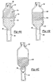
- FIG. 4A The method of operation using the packaging system 50 according to a preferred embodiment of the present invention is shown in Figures 4A through 4E .
- the container 52 is shown with the first compartment 74 being filled with a liquid component 100 and the second compartment 76 being filled with a powdered component 102.
- the liquid component 100 may be a methyl methacrylate monomer containing an amine accelerator and the powdered component 102 may be a poly methyl methacrylate and a copolymer of methyl methacrylate and styrene, together with benzoyl peroxide and barium sulphate.
- An antibiotic material may also be combined with the liquid component 100 or the powdered component 102.
- the vacuum reservoir 86 is initially placed in the extension 66 and the powdered component 102 is placed within the second compartment 76. Thereafter a vacuum is drawn on the extension 66 such that the interior of the extension 66 and the second compartment 76 are maintained in a substantially airless state. The nozzle is then heat sealed at the edge 68 while the vacuum is maintained inside the second compartment 76 and the extension 66. The liquid component 100 is then placed in the first compartment 74 in a similar manner to that described above and then the second compartment 74 is sealed. Care is taken so that little, if any, air enters the first compartment 74 while the first compartment 74 is being filled with the liquid component 100.
- the resulting structure of the packaging system 50 is that which is shown in Figure 1 .
- Figure 4B shows the container 52 shortly after the divider 54 has been removed and the liquid component 100 has started to wet the powdered component 102 so as to form bone cement represented by the area 106.
- the liquid component 100 is driven towards and into the powdered component 102 by the atmospheric pressure acting on the first compartment 74 containing the liquid component 100.
- the residual air in the interstitial voids between the particles of the powdered component 102 is drawn through the barrier mechanism 90 and into the vacuum reservoir 86.
- the in situ wetting of the liquid component 84 into the powdered component 102 is complete. All of the interstitial voids between the particles of the powdered component 102 are filled by the liquid component 100 and the residual air is held inside the vacuum reservoir 86 at a partial vacuum.
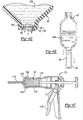
- FIG 4D the portion of the liquid component 100 that is drawn completely through the powdered component 102 is shown to contact the barrier member 94 which resists infiltration of the liquid component 100 into the vacuum reservoir 86.
- the arrows in Figure 4D depict gasses passing through the barrier mechanism 90 into the vacuum reservoir 86.
- the vacuum reservoir 86 and the barrier member 94 cooperate to permit a minimum differential pressure of about 137.895 millibars (about 2 pounds per square inch) to be exerted on the liquid component 100 upon removal of the divider 54 so that substantially all residual interstitial gasses are taken up and the liquid component 100 drawn through and wetting the powder component 102 within about 5 seconds to about 60 seconds after the divider 54 has been released.
- the vacuum reservoir 86 and the barrier member 94 cooperate to permit substantially all residual interstitial gasses to be taken up and the liquid component 100 drawn through the powder component 102 within about 10 seconds to about 30 seconds after the divider 54 has been released when a differential pressure of about 137.895 millibars (about 2 pounds per square inch) is exerted onto the liquid component 100.
- the bone cement 106 within the container 52 may then be dispensed in the manner shown in Figures 4E and 4F .
- the container 52 is placed within a bone cement syringe 114 with the extension 66 passing through the open end 120 of the bone cement syringe 114.
- the extension 66 is passed through a cap 122 and the cap 122 is threadably coupled to the bone cement syringe 114. At least a portion of the extension 66 is severed and the vacuum reservoir 86 is removed.
- a tubular nozzle 112 is then coupled to the cap 122.
- the plunger 116 of the bone cement gun 110 is then displaced toward the flexible container 52 by manipulation of the activation member 118 of the bone cement gun 110. As the plunger 116 compresses the flexible container 52, bone cement 116 is delivered through the tubular member 112.
- the flexible container 52 can be fully compressed, leaving only a small fraction of bone cement inside the flexible container 52.
- the packaging system 50 may be formed to include a vent port 86' as shown in Figure 5 .
- container 52' is substantially similar to container 52 except that container 52' includes a vent port 86' rather than a vacuum reservoir 86.
- vent port 86' includes a tube 88, a barrier mechanism 90 having a barrier member 94 and a plug member 96. Vent port 86' is not charged with vacuum pressure prior to the use of container 52'.
- a vacuum pump 150 is coupled to the vent port 86' via a vacuum hose 152.
- the vacuum pump 150 and the barrier member 94 cooperate to permit a differential pressure to be exerted on the liquid component which causes the liquid component to be drawn through a porous or powder component in the second compartment 76'.
- an externally initiated force may be applied to the first compartment 74' to create a pressure differential to cause the liquid component to be displaced into the porous or powder component in the second compartment 76'.
- the divider 54 may be formed as an integral (i.e., non-removable) barrier between the first and second compartments 74 and 76.
- An example of this construction is disclosed in U.S. Patent No. 5,549,380 entitled “Mixing Device for Manufacturing Bone Cement” . Accordingly, those skilled in the art will understand that the integrity of the divider 54 may be compromised by the removal of the divider, either in whole or in part, or by puncturing, rupturing, impacting, cutting, tearing, severing, or otherwise causing the divider to be opened to permit fluid communication between the first and second compartments 74 and 76.
- first and second compartments 74 and 76 may be non-integral (i.e., separable) from one another.
- An example of this construction is disclosed in U.S. Patent No. 5,852,241 entitled “Method and Device for Feeding Components for Bone Cement Into a Mixing Vessel for These" . Accordingly, those skilled in the art will understand that the integral configuration of the container 52 wherein the first and second compartments 74 and 76 are permanently joined is merely exemplary and that the scope of the present invention will extend to containers where the first and second compartments are joined together prior to the mixing of the contents contained therein.
Landscapes
- Health & Medical Sciences (AREA)
- Chemical Kinetics & Catalysis (AREA)
- Chemical & Material Sciences (AREA)
- Engineering & Computer Science (AREA)
- Life Sciences & Earth Sciences (AREA)
- Surgery (AREA)
- Orthopedic Medicine & Surgery (AREA)
- Medical Informatics (AREA)
- Mechanical Engineering (AREA)
- Molecular Biology (AREA)
- Animal Behavior & Ethology (AREA)
- General Health & Medical Sciences (AREA)
- Public Health (AREA)
- Veterinary Medicine (AREA)
- Heart & Thoracic Surgery (AREA)
- Nuclear Medicine, Radiotherapy & Molecular Imaging (AREA)
- Biomedical Technology (AREA)
- Materials For Medical Uses (AREA)
- Prostheses (AREA)
- Accessories For Mixers (AREA)
- Devices And Processes Conducted In The Presence Of Fluids And Solid Particles (AREA)
Claims (33)
- Behälter (50) zum Verpacken von flüssigen und pulverförmigen Komponenten, die in dem Behälter gemischt werden sollen, wobei der Behälter umfasst:eine erste Kammer (74), die die flüssige Komponente enthält;eine zweite Kammer (76), die die pulverförmige Komponente enthält;eine Trennwand (54), die die erste Kammer von der zweiten Kammer trennt;eine Vakuumquelle (86) in Fluidkommunikation mit der zweiten Kammer,wobei die Vakuumquelle hinreichend groß und hinreichend druckbeständig ist,dass im Wesentlichen alle Gase in den ersten und zweiten Kammern aufgenommen werden können, so dass die flüssigen und pulverförmigen Komponenten gründlich gemischt werden können, nachdem die Intaktheit der Trennwand beschädigt wurde, und die ersten und zweiten Kammern miteinander in Fluidkommunikation gebracht wurden; undeinen Sperrmechanismus (90), der sich zwischen der zweiten Kammer und der Vakuumquelle befindet;dadurch gekennzeichnet, dassder Sperrmechanismus eine aus einem oleophoben Material aufgebaute poröse Membran (94) umfasst, wobei der Sperrmechanismus eine Sperre bildet, die die flüssige Komponente zurückhält, aber Gase in den ersten und zweiten Kammern in die Vakuumquelle einlässt.
- Behälter nach Anspruch 1, wobei die poröse Membran aus einem Material mit einer niedrigen Oberflächenenergie gebildet ist, so dass die flüssige Komponente nicht aus der Oberfläche des Sperrmechanismus aussickern kann.
- Behälter nach Anspruch 2, wobei das oleophobe Material aufgeschäumtes Polytetrafluorethylen ist.
- Behälter nach Anspruch 1, wobei der Sperrmechanismus zudem ein Stopfenbauteil (96) zum Stützen der porösen Membran umfasst.
- Behälter nach Anspruch 4, wobei das Stopfenbauteil aus einem olefinischen Material besteht.
- Behälter nach Anspruch 1, wobei die poröse Membran gegenüber der flüssigen Komponente und der pulverförmigen Komponente inert ist.
- Behälter nach Anspruch 1, wobei die flüssige Komponente ein Acrylmonomer umfasst.
- Behälter nach Anspruch 1, wobei die pulverförmige Komponente ein pulverförmiges Acrylpolymer umfasst.
- Behälter nach Anspruch 1, wobei die flüssigen und pulverförmigen Komponenten so gemischt werden, dass man einen Knochenleim erhält.
- Behälter nach Anspruch 1, wobei die Vakuumquelle ein Vakuumreservoir ist.
- Behälter nach Anspruch 1, wobei die Vakuumquelle eine Vakuumpumpe ist.
- Behälter nach Anspruch 1, wobei die Trennwand ein Klammerbauteil und ein Rückhaltebauteil umfasst, die so miteinander arbeiten, dass eine erste Seite des Behälters gegen eine zweite Seite des Behälters gedrückt wird, so dass man eine Dichtung erhält, die die ersten und zweiten Kammern trennt, und wobei die Trennwand beschädigt wird, indem die Klammer- und Rückhaltebauteile voneinander gelöst werden.
- Behälter nach Anspruch 1, wobei der Sperrmechanismus (90) eine gasdurchlässige Sperre (94) umfasst, die sich zwischen der zweiten Kammer und der Vakuumquelle befindet, wobei die gasdurchlässige Sperre die poröse Membran umfasst, die die flüssige Komponente nicht durchlässt, und die Vakuumquelle aufgrund der gasdurchlässigen Sperre die flüssige Komponente in die zweite Kammer ziehen kann, nachdem die Trennwand beschädigt wurde.
- Behälter nach Anspruch 13, wobei die Vakuumquelle und die gasdurchlässige Sperre nach dem Beschädigen der Trennwand derart miteinander arbeiten, dass ein minimaler Differentialdruck von etwa 137,895 mbar (etwa 2 Pfund pro Quadratzoll) auf die flüssige Komponente ausgeübt wird.
- Behälter nach Anspruch 13, wobei die Vakuumquelle und die gasdurchlässige Sperre nach dem Beschädigen der Trennwand so miteinander arbeiten, dass im Wesentlichen alle restlichen Zwischengase innerhalb von etwa 5 sec bis etwa 60 sec nach dem Lösen der Trennwand aufgenommen werden.
- Behälter nach Anspruch 15, wobei die Vakuumquelle und die gasdurchlässige Sperre so miteinander arbeiten, dass im Wesentlichen alle restlichen Zwischengase innerhalb von etwa 10 sec bis etwa 30 sec nach dem Beschädigen der Trennwand aufgenommen werden.
- Behälter nach Anspruch 13, wobei die gasdurchlässige Sperre für die flüssige Komponente undurchlässig ist, wenn ein Differentialdruck von etwa 137,895 mbar (etwa 2 Pfund pro Quadratzoll) auf die flüssige Komponente ausgeübt wird.
- Behälter nach Anspruch 17, wobei die gasdurchlässige Sperre für die flüssige Komponente undurchlässig ist, wenn ein Differentialdruck von etwa 620,528 mbar (etwa 9 Pfund pro Quadratzoll) auf die flüssige Komponente ausgeübt wird.
- Behälter nach Anspruch 13, wobei die flüssigen und pulverförmigen Komponenten so gemischt werden, dass man einen Knochenleim erhält.
- Behälter nach Anspruch 13, wobei die Vakuumquelle ein Vakuumreservoir ist.
- Behälter nach Anspruch 13, wobei die Vakuumquelle eine Vakuumpumpe ist.
- Behälter nach Anspruch 13, wobei die Trennwand ein Klammerbauteil und ein Rückhaltebauteil umfasst, die so miteinander arbeiten, dass eine erste Seite des Behälters gegen eine zweite Seite des Behälters gedrückt wird, so dass man eine Dichtung erhält, die die ersten und zweiten Kammern unterteilt, und wobei die Trennwand beschädigt wird, indem die Klammer- und Rückhaltebauteile voneinander gelöst werden.
- Behälter nach Anspruch 1, wobei die poröse Membran eine Anzahl von Poren umfasst, die im Allgemeinen so groß sind, dass sie die flüssige Komponente nicht durch den Sperrmechanismus übertragen, wobei die Anzahl Poren auch im Allgemeinen so groß ist, dass eine Fluidkommunikation restlicher Zwischengase in der zweiten Kammer ermöglicht wird, und die Vakuumquelle aufgrund des Sperrmechanismus die flüssige Komponente nach dem Beschädigen der Trennwand in die zweite Kammer ziehen kann.
- Behälter nach Anspruch 23, wobei jede der Anzahl Poren 1 Mikron Maximaldurchmesser hat.
- Behälter nach Anspruch 23, wobei die flüssigen und pulverförmigen Komponenten so gemischt werden, dass man einen Knochenleim erhält.
- Behälter nach Anspruch 23, wobei die Vakuumquelle ein Vakuumreservoir ist.
- Behälter nach Anspruch 23, wobei die Vakuumquelle eine Vakuumpumpe ist.
- Behälter nach Anspruch 23, wobei die Trennwand ein Klammerbauteil und ein Rückhaltebauteil umfasst, die so miteinander arbeiten, dass eine erste Seite des Behälters gegen eine zweite Seite des Behälters gedrückt wird, so dass man eine Dichtung erhält, die die ersten und zweiten Kammern unterteilt, und wobei die Trennwand beschädigt wird, indem die Klammer- und Rückhaltebauteile voneinander gelöst werden.
- Behälter (50) zum Verpacken von flüssigen und pulverförmigen Komponenten, die im Behälter gemischt werden sollen, wobei der Behälter umfasst:eine Trenneinrichtung (54) zum Trennen einer ersten Kammer (74) des Behälters von einer zweiten Kammer (76) des Behälters, wobei die erste Kammer die erste Komponente enthält, und die zweite Kammer die zweiten Komponente enthält;Differentialdruck-Einrichtungen (150/94) zum Ausüben eines Differentialdrucks auf die flüssige Komponente, so dass im Wesentlichen alle restlichen Zwischengase aufgenommen werden, wodurch die flüssigen und pulverförmigen Komponenten beim Lösen der Trenneinrichtung gründlich gemischt werden können; gekennzeichnet durcheine Lüftungseinrichtung (86') in Fluidkommunikation mit der zweiten Kammer, undeine Sperreinrichtung (90), die sich zwischen der zweiten Kammer und der Lüftungseinrichtung befindet, wobei die Sperreinrichtung eine aus einem oleophoben Material gebildete poröse Membran (94) aufweist, und die Sperreinrichtung eine Sperre bildet, die die flüssige Komponente nicht in die Lüftungseinrichtung einlässt.
- Behälter nach Anspruch 29, wobei die Differentialdruckeinrichtung eine Quelle für Vakuumdruck (150) umfasst.
- Behälter nach Anspruch 29, wobei die flüssigen und pulverförmigen Komponenten so gemischt werden, dass man einen Knochenleim erhält.
- Verfahren zum Mischen einer Verbindung, umfassend die Schritte:Bereitstellen eines Behälters (50) mit ersten (74) und zweiten (76) Kammern, wobei die erste Kammer mit einer flüssigen Komponente gefüllt ist, die zweite Kammer mit der pulverförmigen Komponente gefüllt ist, und sie von der ersten Kammer getrennt ist.Koppeln einer Vakuumquelle (150) mit einem Vakuumdruck an die zweite Kammer, so dass die Vakuumquelle in Fluidkommunikation mit der zweiten Kammer ist;Bringen der ersten und zweiten Kammern in Fluidkommunikation miteinander,so dass ein von der Vakuumquelle erzeugter Differentialdruck die flüssige Komponente in die zweite Kammer treibt;Einfügen eines Sperrmechanismus (90) mit einer gasdurchlässigen Sperre (94) zwischen die Vakuumquelle und die zweite Kammer; undMischen der flüssigen Komponente und der pulverförmigen Komponente unter Vakuumdruck,dadurch gekennzeichnet, dassdie gasdurchlässige Sperre (94) aus einem oleophoben Material gebildet wird,wobei die gasdurchlässige Sperre die flüssige Komponente nicht hindurchlässt.
- Verfahren nach Anspruch 32, wobei die Verbindung ein Knochenleim ist.
Applications Claiming Priority (3)
| Application Number | Priority Date | Filing Date | Title |
|---|---|---|---|
| US524846 | 2000-03-14 | ||
| US09/524,846 US6286670B1 (en) | 2000-03-14 | 2000-03-14 | Method and apparatus for mixing a compound utilizing a gas permeable barrier |
| PCT/US2001/008176 WO2001068463A1 (en) | 2000-03-14 | 2001-03-14 | Method and apparatus for mixing a compound utilizing a gas permeable barrier |
Publications (3)
| Publication Number | Publication Date |
|---|---|
| EP1286897A1 EP1286897A1 (de) | 2003-03-05 |
| EP1286897A4 EP1286897A4 (de) | 2007-01-31 |
| EP1286897B1 true EP1286897B1 (de) | 2011-08-10 |
Family
ID=24090892
Family Applications (1)
| Application Number | Title | Priority Date | Filing Date |
|---|---|---|---|
| EP01918670A Expired - Lifetime EP1286897B1 (de) | 2000-03-14 | 2001-03-14 | Verfahren und vorrichtung zum mischen von komponenten mit hilfe einer gasdurchlässigen schicht |
Country Status (5)
| Country | Link |
|---|---|
| US (1) | US6286670B1 (de) |
| EP (1) | EP1286897B1 (de) |
| AT (1) | ATE519690T1 (de) |
| AU (1) | AU2001245721A1 (de) |
| WO (1) | WO2001068463A1 (de) |
Families Citing this family (59)
| Publication number | Priority date | Publication date | Assignee | Title |
|---|---|---|---|---|
| US6648133B1 (en) * | 2001-07-18 | 2003-11-18 | Biomet, Inc. | Device and method for hydrating and rehydrating orthopedic graft materials |
| US7198150B1 (en) | 2001-07-18 | 2007-04-03 | Biomet Manufacturing Corp. | Device and method for hydrating and rehydrating orthopedic graft materials |
| US20030205538A1 (en) | 2002-05-03 | 2003-11-06 | Randel Dorian | Methods and apparatus for isolating platelets from blood |
| US7832566B2 (en) | 2002-05-24 | 2010-11-16 | Biomet Biologics, Llc | Method and apparatus for separating and concentrating a component from a multi-component material including macroparticles |
| US7845499B2 (en) | 2002-05-24 | 2010-12-07 | Biomet Biologics, Llc | Apparatus and method for separating and concentrating fluids containing multiple components |
| US20060278588A1 (en) | 2002-05-24 | 2006-12-14 | Woodell-May Jennifer E | Apparatus and method for separating and concentrating fluids containing multiple components |
| EP1369092B1 (de) * | 2002-06-04 | 2008-08-20 | MTF MediTech Franken GmbH | Verfahren und Vorrichtung zum Befeuchten von nichtbiologischen medizinischen Implantatswerkstoffen |
| US7172071B2 (en) * | 2003-08-05 | 2007-02-06 | Biomet Manufacturing Corp. | Method and apparatus for use of a vacuum package for allograft material |
| US7243788B2 (en) * | 2003-10-22 | 2007-07-17 | Kimberly-Clark Worldwide, Inc. | Package for segregating and mixing substances |
| US20050105384A1 (en) * | 2003-11-18 | 2005-05-19 | Scimed Life Systems, Inc. | Apparatus for mixing and dispensing a multi-component bone cement |
| US7524103B2 (en) | 2003-11-18 | 2009-04-28 | Boston Scientific Scimed, Inc. | Apparatus for mixing and dispensing a multi-component bone cement |
| AU2004294324B2 (en) * | 2003-12-02 | 2010-05-27 | Fuso Pharmaceutical Industries, Ltd. | Dual-chamber container |
| US7275640B2 (en) * | 2004-02-05 | 2007-10-02 | Boston Scientific Scimed, Inc. | Packaging for imparting anti-microbial properties to a medical device |
| US7594578B2 (en) * | 2005-01-26 | 2009-09-29 | Biomet Manufacturing Corp. | Method and apparatus for storing bone cement components |
| US7717257B1 (en) * | 2006-05-02 | 2010-05-18 | Henkel Corporation | Multi-section package for a mold release agent and a wipe |
| US8567609B2 (en) | 2006-05-25 | 2013-10-29 | Biomet Biologics, Llc | Apparatus and method for separating and concentrating fluids containing multiple components |
| US20080154229A1 (en) * | 2006-07-26 | 2008-06-26 | Lambert Systems, L.L.C. | Device And Method For Mixing And Delivering Bone Cement Precursors |
| WO2008030668A2 (en) * | 2006-07-26 | 2008-03-13 | Lambert Systems, L.L.C. | Biocompatible anchoring device for a soft tissue graft, method of making and method of using |
| US20080097358A1 (en) * | 2006-10-20 | 2008-04-24 | Dovonan James A | Personal Hygiene wipe |
| US20080097356A1 (en) * | 2006-10-20 | 2008-04-24 | Donovan James A | Personal hygiene wipe |
| US20080202962A1 (en) * | 2007-02-23 | 2008-08-28 | Brouard Roger H | Tool bag |
| JP5479319B2 (ja) | 2007-04-12 | 2014-04-23 | バイオメット・バイオロジックス・リミテッド・ライアビリティ・カンパニー | ブイ式懸濁液分画システム |
| US8328024B2 (en) | 2007-04-12 | 2012-12-11 | Hanuman, Llc | Buoy suspension fractionation system |
| US9358135B2 (en) * | 2007-04-17 | 2016-06-07 | Warsaw Orthopedic, Inc. | Devices, methods and systems for hydrating a medical implant material |
| US20090090349A1 (en) * | 2007-10-05 | 2009-04-09 | Donovan James A | Pan in pan heater |
| US20090090350A1 (en) * | 2007-10-05 | 2009-04-09 | James A. Donovan | Combined food and wipe heater |
| US8206143B2 (en) * | 2007-12-13 | 2012-06-26 | Biomet Manufacturing Corp. | Modular articulating cement spacer |
| US7637729B2 (en) * | 2007-12-13 | 2009-12-29 | Biomet Manufacturing Corp. | Modular articulating cement spacer mold |
| EP2567692B1 (de) | 2008-02-27 | 2016-04-06 | Biomet Biologics, LLC | Verwendung einer Vorrichtung zur Erzeugung Interleukin-1-rezeptorantagonistreicher Lösungen |
| WO2009111338A1 (en) | 2008-02-29 | 2009-09-11 | Biomet Manufacturing Corp. | A system and process for separating a material |
| US7951123B2 (en) * | 2008-03-05 | 2011-05-31 | James A. Donovan | Spa wax heating device |
| US20090277915A1 (en) * | 2008-05-12 | 2009-11-12 | James A. Donovan | Personal hygiene wipe package |
| US8480289B2 (en) | 2008-08-22 | 2013-07-09 | Biomet Manufacturing, Llc | Bone cement mixing cartridge and method of use |
| US20100208546A1 (en) * | 2009-02-19 | 2010-08-19 | Jere Ferguson | Activation device |
| US8187475B2 (en) | 2009-03-06 | 2012-05-29 | Biomet Biologics, Llc | Method and apparatus for producing autologous thrombin |
| DE102009013211B4 (de) | 2009-03-17 | 2012-04-19 | Aap Biomaterials Gmbh | Vakuum-Mischvorrichtung für Knochenzement sowie Verfahren zum Mischen von Knochenzement |
| US8505172B2 (en) * | 2009-03-30 | 2013-08-13 | Zafer Termanini | Removable pouch partition |
| US8313954B2 (en) | 2009-04-03 | 2012-11-20 | Biomet Biologics, Llc | All-in-one means of separating blood components |
| US9011800B2 (en) | 2009-07-16 | 2015-04-21 | Biomet Biologics, Llc | Method and apparatus for separating biological materials |
| EP2287084A1 (de) * | 2009-08-21 | 2011-02-23 | CMP Products Limited | Ausgabevorrichtung für härtbares flüssiges Material |
| SG178839A1 (en) | 2009-08-21 | 2012-04-27 | Cmp Products Ltd | Filler assembly for cable gland |
| US10193321B2 (en) | 2009-08-21 | 2019-01-29 | Cmp Products Limited | Filler assembly for cable gland |
| US8591391B2 (en) | 2010-04-12 | 2013-11-26 | Biomet Biologics, Llc | Method and apparatus for separating a material |
| DE102011101486A1 (de) * | 2011-05-13 | 2012-11-15 | Heraeus Medical Gmbh | Vorrichtung und Verfahren zum Entgasen und Austragen von Knochenzement |
| DE102011112516B4 (de) | 2011-09-07 | 2024-02-29 | Stryker European Operations Holdings Llc | Gebinde mit einem Behälter zur Aufnahme einer Flüssigkeit und einer Flüssigkeitsentnahmeeinrichtung |
| DE102012016507A1 (de) * | 2012-08-20 | 2014-03-13 | Medical Service Gmbh | Benetzungsvorrichtung mit lösbar verriegelter Klammer |
| US9642956B2 (en) | 2012-08-27 | 2017-05-09 | Biomet Biologics, Llc | Apparatus and method for separating and concentrating fluids containing multiple components |
| US10208095B2 (en) | 2013-03-15 | 2019-02-19 | Biomet Manufacturing, Llc | Methods for making cytokine compositions from tissues using non-centrifugal methods |
| US10143725B2 (en) | 2013-03-15 | 2018-12-04 | Biomet Biologics, Llc | Treatment of pain using protein solutions |
| US9895418B2 (en) | 2013-03-15 | 2018-02-20 | Biomet Biologics, Llc | Treatment of peripheral vascular disease using protein solutions |
| US9950035B2 (en) | 2013-03-15 | 2018-04-24 | Biomet Biologics, Llc | Methods and non-immunogenic compositions for treating inflammatory disorders |
| US20140271589A1 (en) | 2013-03-15 | 2014-09-18 | Biomet Biologics, Llc | Treatment of collagen defects using protein solutions |
| US10968027B2 (en) | 2013-07-02 | 2021-04-06 | Memorial Sloan-Kettering Cancer Center | Apparatus, arrangement and method for providing skin care ingredients |
| WO2015002960A1 (en) * | 2013-07-02 | 2015-01-08 | Memorial Sloan Kettering Cancer Center | Apparatus, arrangement and method for providing skin care ingredients |
| US20160206776A1 (en) * | 2013-08-27 | 2016-07-21 | Biomet Manufacturing, Llc | Apparatus for producing a doughy bone cement shape |
| US10653470B2 (en) * | 2014-02-19 | 2020-05-19 | Spinal Generation, LLC | Compressible mixing and delivery system for medical substances |
| DE102014005569A1 (de) * | 2014-04-16 | 2015-10-22 | Fresenius Medical Care Deutschland Gmbh | Mehrkammerbeutelöffnungshilfe |
| FR3067918B1 (fr) * | 2017-06-23 | 2019-07-19 | Laboratoires M&L | Capsule deformable a usage unique comprenant une quantite predeterminee d'une phase d'un produit cosmetique |
| CN109529725A (zh) * | 2018-12-31 | 2019-03-29 | 柳州申通汽车科技有限公司 | 汽车尾气三元催化剂的制备方法 |
Family Cites Families (7)
| Publication number | Priority date | Publication date | Assignee | Title |
|---|---|---|---|---|
| JPH0549643U (ja) * | 1991-11-14 | 1993-06-29 | 有限会社クリーン・パック | 自己密封性圧縮包装袋及び圧縮包装器セット |
| US5370221A (en) | 1993-01-29 | 1994-12-06 | Biomet, Inc. | Flexible package for bone cement components |
| US5398483A (en) | 1993-01-29 | 1995-03-21 | Polymers Reconstructive A/S | Method and apparatus for packaging, mixing and delivering bone cement |
| US5788078A (en) * | 1993-08-02 | 1998-08-04 | Free Flow Packaging Corporation | Vacuum formed cushioning device and method of making and using the same |
| US5588745A (en) * | 1994-09-02 | 1996-12-31 | Howmedica | Methods and apparatus for mixing bone cement components using an evacuated mixing chamber |
| DE19718648A1 (de) | 1997-05-02 | 1998-11-05 | Merck Patent Gmbh | Verfahren und Vorrichtung zur Herstellung von steril verpacktem Knochenzement |
| US5951160A (en) | 1997-11-20 | 1999-09-14 | Biomet, Inc. | Method and apparatus for packaging, mixing and delivering bone cement |
-
2000
- 2000-03-14 US US09/524,846 patent/US6286670B1/en not_active Expired - Lifetime
-
2001
- 2001-03-14 AU AU2001245721A patent/AU2001245721A1/en not_active Abandoned
- 2001-03-14 WO PCT/US2001/008176 patent/WO2001068463A1/en not_active Ceased
- 2001-03-14 AT AT01918670T patent/ATE519690T1/de not_active IP Right Cessation
- 2001-03-14 EP EP01918670A patent/EP1286897B1/de not_active Expired - Lifetime
Also Published As
| Publication number | Publication date |
|---|---|
| AU2001245721A1 (en) | 2001-09-24 |
| EP1286897A1 (de) | 2003-03-05 |
| ATE519690T1 (de) | 2011-08-15 |
| EP1286897A4 (de) | 2007-01-31 |
| US6286670B1 (en) | 2001-09-11 |
| WO2001068463A1 (en) | 2001-09-20 |
Similar Documents
| Publication | Publication Date | Title |
|---|---|---|
| EP1286897B1 (de) | Verfahren und vorrichtung zum mischen von komponenten mit hilfe einer gasdurchlässigen schicht | |
| EP0682621B1 (de) | Verfahren und vorrichtung zum verpacken, mischen und spenden von knochenzement | |
| EP0796653B1 (de) | System und Verfahren zum Mischen von Knochenzement | |
| EP0702594B1 (de) | Verfahren und vorrichtung zum vorbereiten und abgeben von knochenzement | |
| US11154343B2 (en) | Device and method for storing and mixing bone cement | |
| AU704952B2 (en) | Bone cement mixer | |
| CN108792304A (zh) | 在输送柱塞上具有封闭装置的骨水泥施加设备 | |
| JP2019107449A (ja) | アンプル収容部内にスペーサを備えた骨セメント混合装置 | |
| AU2016269440B2 (en) | Vacuum mixing device with operating element and pump for mixing polymethylmethacrylate bone cement | |
| US10016228B2 (en) | Mixing device with operating element and pressure pump for mixing polymethylmethacrylate bone cement | |
| DE102017113126A1 (de) | Knochenzementapplikator mit Leitungselement und Verschlussaufnahme | |
| US20240407818A1 (en) | Mixing system with side ampule breaker | |
| US7748526B2 (en) | Mixing device | |
| US12408964B2 (en) | Device and method for providing a bone cement paste | |
| US20250288340A1 (en) | Bone cement mixing system having puncture connection and multifunctional plunger |
Legal Events
| Date | Code | Title | Description |
|---|---|---|---|
| PUAI | Public reference made under article 153(3) epc to a published international application that has entered the european phase |
Free format text: ORIGINAL CODE: 0009012 |
|
| 17P | Request for examination filed |
Effective date: 20021009 |
|
| AK | Designated contracting states |
Kind code of ref document: A1 Designated state(s): AT BE CH CY DE DK ES FI FR GB GR IE IT LI LU MC NL PT SE TR |
|
| AX | Request for extension of the european patent |
Extension state: AL LT LV MK RO SI |
|
| A4 | Supplementary search report drawn up and despatched |
Effective date: 20070104 |
|
| RIC1 | Information provided on ipc code assigned before grant |
Ipc: B65D 81/32 20060101AFI20061228BHEP Ipc: A61F 2/46 20060101ALI20061228BHEP |
|
| 17Q | First examination report despatched |
Effective date: 20071126 |
|
| GRAP | Despatch of communication of intention to grant a patent |
Free format text: ORIGINAL CODE: EPIDOSNIGR1 |
|
| GRAS | Grant fee paid |
Free format text: ORIGINAL CODE: EPIDOSNIGR3 |
|
| GRAA | (expected) grant |
Free format text: ORIGINAL CODE: 0009210 |
|
| AK | Designated contracting states |
Kind code of ref document: B1 Designated state(s): AT BE CH CY DE DK ES FI FR GB GR IE IT LI LU MC NL PT SE TR |
|
| REG | Reference to a national code |
Ref country code: GB Ref legal event code: FG4D |
|
| REG | Reference to a national code |
Ref country code: CH Ref legal event code: EP |
|
| REG | Reference to a national code |
Ref country code: IE Ref legal event code: FG4D |
|
| REG | Reference to a national code |
Ref country code: DE Ref legal event code: R096 Ref document number: 60145114 Country of ref document: DE Effective date: 20111013 |
|
| REG | Reference to a national code |
Ref country code: NL Ref legal event code: VDEP Effective date: 20110810 |
|
| PG25 | Lapsed in a contracting state [announced via postgrant information from national office to epo] |
Ref country code: SE Free format text: LAPSE BECAUSE OF FAILURE TO SUBMIT A TRANSLATION OF THE DESCRIPTION OR TO PAY THE FEE WITHIN THE PRESCRIBED TIME-LIMIT Effective date: 20110810 Ref country code: PT Free format text: LAPSE BECAUSE OF FAILURE TO SUBMIT A TRANSLATION OF THE DESCRIPTION OR TO PAY THE FEE WITHIN THE PRESCRIBED TIME-LIMIT Effective date: 20111212 Ref country code: NL Free format text: LAPSE BECAUSE OF FAILURE TO SUBMIT A TRANSLATION OF THE DESCRIPTION OR TO PAY THE FEE WITHIN THE PRESCRIBED TIME-LIMIT Effective date: 20110810 Ref country code: FI Free format text: LAPSE BECAUSE OF FAILURE TO SUBMIT A TRANSLATION OF THE DESCRIPTION OR TO PAY THE FEE WITHIN THE PRESCRIBED TIME-LIMIT Effective date: 20110810 |
|
| REG | Reference to a national code |
Ref country code: AT Ref legal event code: MK05 Ref document number: 519690 Country of ref document: AT Kind code of ref document: T Effective date: 20110810 |
|
| PG25 | Lapsed in a contracting state [announced via postgrant information from national office to epo] |
Ref country code: AT Free format text: LAPSE BECAUSE OF FAILURE TO SUBMIT A TRANSLATION OF THE DESCRIPTION OR TO PAY THE FEE WITHIN THE PRESCRIBED TIME-LIMIT Effective date: 20110810 Ref country code: GR Free format text: LAPSE BECAUSE OF FAILURE TO SUBMIT A TRANSLATION OF THE DESCRIPTION OR TO PAY THE FEE WITHIN THE PRESCRIBED TIME-LIMIT Effective date: 20111111 Ref country code: CY Free format text: LAPSE BECAUSE OF FAILURE TO SUBMIT A TRANSLATION OF THE DESCRIPTION OR TO PAY THE FEE WITHIN THE PRESCRIBED TIME-LIMIT Effective date: 20110810 |
|
| PG25 | Lapsed in a contracting state [announced via postgrant information from national office to epo] |
Ref country code: BE Free format text: LAPSE BECAUSE OF FAILURE TO SUBMIT A TRANSLATION OF THE DESCRIPTION OR TO PAY THE FEE WITHIN THE PRESCRIBED TIME-LIMIT Effective date: 20110810 |
|
| PLBE | No opposition filed within time limit |
Free format text: ORIGINAL CODE: 0009261 |
|
| STAA | Information on the status of an ep patent application or granted ep patent |
Free format text: STATUS: NO OPPOSITION FILED WITHIN TIME LIMIT |
|
| PG25 | Lapsed in a contracting state [announced via postgrant information from national office to epo] |
Ref country code: DK Free format text: LAPSE BECAUSE OF FAILURE TO SUBMIT A TRANSLATION OF THE DESCRIPTION OR TO PAY THE FEE WITHIN THE PRESCRIBED TIME-LIMIT Effective date: 20110810 |
|
| 26N | No opposition filed |
Effective date: 20120511 |
|
| REG | Reference to a national code |
Ref country code: DE Ref legal event code: R097 Ref document number: 60145114 Country of ref document: DE Effective date: 20120511 |
|
| PG25 | Lapsed in a contracting state [announced via postgrant information from national office to epo] |
Ref country code: MC Free format text: LAPSE BECAUSE OF NON-PAYMENT OF DUE FEES Effective date: 20120331 |
|
| REG | Reference to a national code |
Ref country code: CH Ref legal event code: PL |
|
| REG | Reference to a national code |
Ref country code: IE Ref legal event code: MM4A |
|
| PG25 | Lapsed in a contracting state [announced via postgrant information from national office to epo] |
Ref country code: CH Free format text: LAPSE BECAUSE OF NON-PAYMENT OF DUE FEES Effective date: 20120331 Ref country code: LI Free format text: LAPSE BECAUSE OF NON-PAYMENT OF DUE FEES Effective date: 20120331 Ref country code: IE Free format text: LAPSE BECAUSE OF NON-PAYMENT OF DUE FEES Effective date: 20120314 |
|
| PG25 | Lapsed in a contracting state [announced via postgrant information from national office to epo] |
Ref country code: ES Free format text: LAPSE BECAUSE OF FAILURE TO SUBMIT A TRANSLATION OF THE DESCRIPTION OR TO PAY THE FEE WITHIN THE PRESCRIBED TIME-LIMIT Effective date: 20111121 |
|
| PG25 | Lapsed in a contracting state [announced via postgrant information from national office to epo] |
Ref country code: TR Free format text: LAPSE BECAUSE OF FAILURE TO SUBMIT A TRANSLATION OF THE DESCRIPTION OR TO PAY THE FEE WITHIN THE PRESCRIBED TIME-LIMIT Effective date: 20110810 |
|
| PG25 | Lapsed in a contracting state [announced via postgrant information from national office to epo] |
Ref country code: LU Free format text: LAPSE BECAUSE OF NON-PAYMENT OF DUE FEES Effective date: 20120314 |
|
| REG | Reference to a national code |
Ref country code: FR Ref legal event code: PLFP Year of fee payment: 16 |
|
| REG | Reference to a national code |
Ref country code: FR Ref legal event code: PLFP Year of fee payment: 17 |
|
| PGFP | Annual fee paid to national office [announced via postgrant information from national office to epo] |
Ref country code: DE Payment date: 20170307 Year of fee payment: 17 Ref country code: FR Payment date: 20170213 Year of fee payment: 17 |
|
| PGFP | Annual fee paid to national office [announced via postgrant information from national office to epo] |
Ref country code: GB Payment date: 20170308 Year of fee payment: 17 |
|
| PGFP | Annual fee paid to national office [announced via postgrant information from national office to epo] |
Ref country code: IT Payment date: 20170320 Year of fee payment: 17 |
|
| REG | Reference to a national code |
Ref country code: DE Ref legal event code: R119 Ref document number: 60145114 Country of ref document: DE |
|
| GBPC | Gb: european patent ceased through non-payment of renewal fee |
Effective date: 20180314 |
|
| PG25 | Lapsed in a contracting state [announced via postgrant information from national office to epo] |
Ref country code: DE Free format text: LAPSE BECAUSE OF NON-PAYMENT OF DUE FEES Effective date: 20181002 |
|
| PG25 | Lapsed in a contracting state [announced via postgrant information from national office to epo] |
Ref country code: IT Free format text: LAPSE BECAUSE OF NON-PAYMENT OF DUE FEES Effective date: 20180314 Ref country code: GB Free format text: LAPSE BECAUSE OF NON-PAYMENT OF DUE FEES Effective date: 20180314 |
|
| PG25 | Lapsed in a contracting state [announced via postgrant information from national office to epo] |
Ref country code: FR Free format text: LAPSE BECAUSE OF NON-PAYMENT OF DUE FEES Effective date: 20180331 |