EP1287227B1 - Dispositif de localisation de porte de derrick de fond et procede d'utilisation correspondant - Google Patents
Dispositif de localisation de porte de derrick de fond et procede d'utilisation correspondant Download PDFInfo
- Publication number
- EP1287227B1 EP1287227B1 EP01923821A EP01923821A EP1287227B1 EP 1287227 B1 EP1287227 B1 EP 1287227B1 EP 01923821 A EP01923821 A EP 01923821A EP 01923821 A EP01923821 A EP 01923821A EP 1287227 B1 EP1287227 B1 EP 1287227B1
- Authority
- EP
- European Patent Office
- Prior art keywords
- window
- engaging member
- piston
- downhole
- window engaging
- Prior art date
- Legal status (The legal status is an assumption and is not a legal conclusion. Google has not performed a legal analysis and makes no representation as to the accuracy of the status listed.)
- Expired - Lifetime
Links
Images





Classifications
-
- E—FIXED CONSTRUCTIONS
- E21—EARTH OR ROCK DRILLING; MINING
- E21B—EARTH OR ROCK DRILLING; OBTAINING OIL, GAS, WATER, SOLUBLE OR MELTABLE MATERIALS OR A SLURRY OF MINERALS FROM WELLS
- E21B23/00—Apparatus for displacing, setting, locking, releasing or removing tools, packers or the like in boreholes or wells
- E21B23/02—Apparatus for displacing, setting, locking, releasing or removing tools, packers or the like in boreholes or wells for locking the tools or the like in landing nipples or in recesses between adjacent sections of tubing
-
- E—FIXED CONSTRUCTIONS
- E21—EARTH OR ROCK DRILLING; MINING
- E21B—EARTH OR ROCK DRILLING; OBTAINING OIL, GAS, WATER, SOLUBLE OR MELTABLE MATERIALS OR A SLURRY OF MINERALS FROM WELLS
- E21B41/00—Equipment or details not covered by groups E21B15/00 - E21B40/00
- E21B41/0035—Apparatus or methods for multilateral well technology, e.g. for the completion of or workover on wells with one or more lateral branches
-
- E—FIXED CONSTRUCTIONS
- E21—EARTH OR ROCK DRILLING; MINING
- E21B—EARTH OR ROCK DRILLING; OBTAINING OIL, GAS, WATER, SOLUBLE OR MELTABLE MATERIALS OR A SLURRY OF MINERALS FROM WELLS
- E21B47/00—Survey of boreholes or wells
- E21B47/09—Locating or determining the position of objects in boreholes or wells, e.g. the position of an extending arm; Identifying the free or blocked portions of pipes
Definitions
- the present invention relates to a method and apparatus for use in downhole oil and gas drilling operations, particularly, but not exclusively, to a method and apparatus used in conjunction with a downhole single trip whipstock assembly, for locating a window in a well bore casing and determining the depth and orientation of said window.
- a window is typically formed with a whipstock assembly which is located at the required depth and orientated appropriately so as to laterally deflect a milling tool from the main borehole into the surrounding formation.
- pre-cut or pre-formed windows can also be used. These may be run in hole as part of the casing string and generally in conjunction with a profile sub located below the bottom of the window. The profile sub provides an appropriate means onto which equipment may be latched.
- a suitable lining and/or operational equipment may be run by using a whipstock or alternative means as a deflector.
- the deflection of equipment into the lateral may generally be achieved quite readily since the depth (i.e. the distance downhole) and orientation (i.e. the angular position about the well bore longitudinal axis) of the window are known and suitable deflecting equipment is already appropriately set.
- suitable deflecting equipment is already appropriately set.
- circumstances can arise when a main borehole is known to be provided with a lateral borehole, but the precise depth and orientation of the window is unclear. In this event, the proper positioning of downhole equipment (such as a whipstock) relative to the window is difficult to achieve. Consequential delays in running equipment into a lateral borehole can be highly inconvenient and extremely expensive.
- a tool for use in orienting a diverter assembly is illustrated in US-A-6012516 .
- this tool no means are provided for selectively holding the latch member 20 in a retracted position and accordingly, because of the form of the latch member 20, it could not be run past obstructions or windows in the well casing as the tool was being deployed to the required use position.
- the design requires a special purpose formation pre-positioned within the well casing in order to ensure orientation of the deflector tool.
- the apparatus for determining the depth and orientation of a window in a wellbore, the apparatus comprising: a body; and a window engaging member mounted on said body so as to be movable between a retracted position ( Fig. 1 ) and an extended position ( Fig.
- the window engaging member projecting a greater distance from said body when in the extended position than when in the retracted position, the window engaging member forming a hook which can project into a wellbore window when the window engaging member is in the extended position during use, the hook being adapted to engage with a first portion of the edge which defines the window in such a way that, when pressed against said edge, the hook tends to slide along the edge so as to locate the hook centrally in said window at one end thereof before preventing further movement of the downhole apparatus in the direction of pressing, the window engaging member also having a camming portion adapted to engage a second portion of said edge in such a way that, when the camming portion is pressed against said second portion, the window engaging member is moved towards the retracted position so as to permit movement of the downhole apparatus past said window characterised in that the apparatus includes securing means for holding the window engaging member in its retracted position, the securing means being selectively releasable to permit the window engaging member to move from the retracted
- the depth and orientation of a window may be determined with the apparatus of the present invention by moving the engaging member into the extended position and thereby projecting said member into the window.
- the apparatus may then be moved axially within the well bore (either by pushing an associated conveying string downhole or by pulling said conveying string uphole) so that the engaging member slides along a well bore edge defining the window.
- the apparatus is rotated within the well bore so as to locate centrally on the window longitudinal axis (assuming the window is arranged parallel to the well bore axis rather than skewed relative thereto).
- the apparatus is thereby orientated relative to the window. Once the engaging member reaches the end of the window, further axial movement of the apparatus within the well bore is prevented and the depth of the window is thereby indicated.
- the engaging member is adapted to prevent movement of the downhole apparatus in the direction of pressing by means of a hooked portion provided on the engaging member. It is also preferable for the engaging member to be provided with a camming portion which permits an engagement with a window portion which moves the engaging member towards the retracted position. The engaging member preferably moves as a whole towards the extended position. Biasing means may also be provided to press the engaging member towards the extended position.
- Said means may comprise a piston for moving guide rails of one of the engaging member and apparatus body into alignment with guide slots provided in the other of the engaging member and apparatus body.
- the piston may be movable by the application of static hydraulic pressure.
- the piston may also be secured to the apparatus body by means of a shear pin.
- the engaging member may be movable between retracted and extended positions by means of a cam provided on a piston movable relative to the engaging member.
- the engaging member may be provided with a cam for cooperating with the piston cam.
- the piston may be biased by biasing means to a first position in which the engaging member may locate in the retracted position. It is also preferable for the piston to be movable against the bias of the biasing means, under the application of dynamic hydraulic pressure, to a second position in which the engaging member is cammed to the extended position.
- the piston may be biased by means of a spring.
- the engaging member may also be biased towards the retracted position.
- the engaging member may be biased by means of a biasing member mounted on the apparatus body which is biased towards a cam surface of the engaging member so as to, in turn, bias the engaging member towards the retracted position.
- the biasing member may be biased towards said cam surface by means of a spring.
- the engaging member may be further preferable for the engaging member to rotate between the retracted and extended positions about a pivot.
- the apparatus may be provided with splines for fixing the angular position of the apparatus relative to further downhole apparatus.
- the present invention also provides a method of determining the depth and orientation of a window in a well bore using the apparatus defined above, the method comprising the steps of running said apparatus into a well bore; projecting the engaging member into the window; and moving the apparatus within the well bore so that the engaging member locates centrally in a portion of the window before stopping said movement.
- the portion of window may be an uphole or downhole end of the window.
- the method preferably comprises the further step of moving the apparatus so that the engaging member is pressed against a second portion of the window and thereby moved towards the retracted position so as to permit movement of said apparatus past said window.
- the method may comprise the yet further step of moving said apparatus past said window. Further downhole apparatus may then be located adjacent said window.
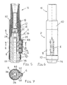
- a first embodiment of the present invention i.e. a first window finder 2 is shown in Figures 1-7 of the accompanying drawings.
- the first window finder 2 is mechanically settable (as opposed to hydraulically settable) and is made up of a body 4, a window engaging member 6 (or dog) mounted in the body 4, and means for moving the window engaging member 6 relative to the body 4 between retracted and extended positions.
- the body 4 incorporates an elongate cylindrical member 8 and a retaining nut 10.
- One end of the elongate cylindrical member 8 (the uphole end) is provided with a cylindrically shaped connecting portion 12, the external surface of which is provided with a screwthread 14 enabling connection of the first window finder 2 to a connecting sub 16.
- the internal surface of the connecting portion 12 is provided with splines 18 allowing a desired angular orientation of the first window finder 2 relative to the connecting sub 16 and any associated downhole equipment. The connection of the first window finder 2 to the connecting sub 16 will be described in greater detail below.
- the elongate cylindrical member 8 is provided with a bore 20 longitudinally extending from the uphole end of said member 8 to a downhole end thereof.
- the diameter of the bore 20 increases at two locations downhole of the connecting portion 12 by virtue of two downhole facing internal shoulders 22, 24.
- the portion of the bore 20 located below the upper internal shoulder 22 slidably receives a cylindrical piston 26 which is used to release the window engaging member 6 from a retracted position (see Figures 1-3 ).
- the portion of elongate cylindrical member 8 located below the lower internal shoulder 24 is provided with a longitudinally extending elongate slot 28 through which, in use, the window engaging member 6 projects.
- the slot 28 is provided through the full thickness of the cylindrical member 8 and extends longitudinally so as to provide an opening 30 in the downhole end of said member.
- the opening 30 assists with assembly of the window finder 2 by allowing the cylindrical piston 26 and window engaging member 6 to be together slid into the bore 20 and elongate slot 28 of the cylindrical member 8.
- the edge of the elongate slot 28 is provided with two longitudinally spaced pairs of guide slots 32.
- the two guide slots 32 of each pair are provided opposite one another on the longitudinally extending edges of the elongate slot 28.
- the guide slots 32 themselves extend laterally and, when in use, provide a guide for the lateral movement of the window engaging member 6 as said member 6 moves between retracted and extended positions (see Figure 2 in particular).
- the cylindrical piston 26 is provided with a bore 34 longitudinally extending therethrough.
- An uphole facing external shoulder 36 is provided adjacent an uphole end of the cylindrical piston 26 for abutment with the lower internal shoulder 24 of the cylindrical member 8.
- the dimensions of the cylindrical piston 26 are such that the outer diameter of the portion of piston 26 located downhole of the external shoulder 26 slidably engages with the inner diameter of the portion of cylindrical member 8 located downhole of the lower internal shoulder 24.
- the outer diameter of the portion of cylindrical piston 26 located uphole of the external shoulder 36 slidably engages with the inner diameter of the portion of cylindrical member 8 located between the upper and lower internal shoulders 22, 24.
- One side of the cylindrical piston 26 is provided with a longitudinally extending elongate recess 38 for slidably receiving the window engaging member 6.
- the relative dimensions of the recess 38 and engaging member 6 are such that the engaging member 6 cannot move uphole, downhole, side to side or twist within the recess 38. Nevertheless, the arrangement is such that the engaging member 6 can readily slide laterally in and out of the recess 38. Furthermore, the depth of the recess 38 is such that, in the assembled window finder 2, the engaging member 6 may be pressed into the recess 38 so as not to project beyond the external diameter of the cylindrical member 8.
- a circumferentially extending groove 40 is provided on the exterior of the downhole portion of the piston 26.
- FIG. 4 A perspective view of the window engaging member 6 is shown in Figure 4 of the accompanying drawings.
- the engaging member 6 is provided with a base portion 44 and two pairs of guide rails 46 (only one guide rail of each pair is shown in Figure 4 ) for slidably engaging the elongate recess 38.
- the guide rails 46 are dimensioned and spaced relative to one another so as to be receivable within the guide slots 32.
- An uphole end of the engaging member 6 is provided with a hook portion 48 for locating about a well bore window when in use.
- a downhole end of the engaging member 6 is provided with a camming portion 50 for cammingly engaging a well bore window when in use.
- Each cylindrical recess 52 receives a compression spring 54 which, in the assembled window finder 2, presses against the recess 38 so as to bias the engaging member 6 towards the extended position. So as to equalise the fluid pressure external to the window finder 2 with that between the engaging member 6 and piston 26, and thereby assist the lateral movement of the engaging member 6, the engaging member 6 is provided with a vent port 56.
- the vent port 56 provides fluid communication between the exterior of the window finder 2 and the middle cylindrical recess 52.
- the vent port 56 may also assist with assembly of the window finder 2 by combining with a threaded rod and providing means for manually retracting the engaging member 6 and clamping said member 6 in the retracted position.
- the threaded rod (not shown) may be inserted into the vent port 56 and threadedly secured in a threaded recess (not shown) provided in the base of the elongate recess 38 of the piston 26.
- a nut (not shown) may then be threadedly engaged with a portion of rod extending outwardly from the vent port 56.
- the nut may be screwed down over the rod towards the piston 26 and, in so doing, abut the outer surface of the engaging member 6 and press the engaging member 6 into the retracted position.
- the piston 26 and engaging member 6 With the engaging member 6 clamped in the retracted position against the bias of the compression springs 54, the piston 26 and engaging member 6 may be pushed into the cylindrical member 8. The rod and nut may then be removed.
- the arrangement of the elongate slot 28 and guide slots 32 of the cylindrical member 8 relative to the engaging member 6 is such that the guide rails 46 locate downhole of the associated guide slots 32.
- Outer ends 58 (see Figure 4 ) of the guide rails 46 abut the inner diameter of the cylindrical member 8 and thereby retain the window engaging member 6 in the retracted position against the bias of the three compression springs 54.
- the window finder 2 may be run in hole without significant risk of the engaging member 6 deploying to the extended position prematurely.
- the shear pin 42 is sheared and the cylindrical piston 26 is moved uphole within the cylindrical member 8.
- the window finder 2 is connected to a conveying string by means of a connecting sub 16.
- a precise angular orientation of the window finder 2 relative to the conveying string may be achieved by means of the splines 18.
- the window finder 2 and connecting sub 16 are releasably secured to one another by means of a connecting collar 60.
- the connecting collar 60 has internal screwthreads which engage the external screwthreads 14 and thereby, through the interaction of mating shoulders 62 on the connecting collar 60 and connecting sub 16, rigidly secure the connecting sub 16 and window finder 2 together.
- the first window finder 2 is set mechanically.
- the piston 26 is moved from its initial position, wherein the shear pin 42 is located in the circumferential groove 40, to its uphole position, wherein the guide rails 46 are aligned with the guide slots 32, by forcing the piston 26 uphole within the body 4 with mechanical means.
- This may involve locating the downhole portion of the piston 26 at the end of a well bore or on a well bore plug and allowing the weight of the conveying string to shear the shear pin 42 and press the body 4 downhole whilst the piston 26 remains stationery.
- a second window finder 2' is hydraulically set.
- the second window finder 2' is essentially a modified version of the first window finder 2.
- the majority of the second window finder 2' is identical to the first window finder 2 and like components have been labelled in the accompanying drawings with like reference numerals. The construction and operation of these like components will not be further described.
- an alternative retaining nut 10' is provided as a cap, together with an appropriate O-ring seal 62, for sealing the downhole ends of the cylindrical member and cylindrical piston bores 20, 34. In this way, the interior of the window finder 2' may be pressurised.
- a further O-ring seal 64 is provided on the piston 26 uphole of the external shoulder 36 for sliding engagement with the cylindrical surface of the piston 26 located between the upper and lower internal shoulders 22, 24.
- a modified connecting sub 16 is used which has a cylindrical portion 66 extending from the downhole end thereof into the uphole portion of the bore 20 of the elongate cylindrical member 8. The exterior surface of this cylindrical portion 66 is provided with a yet further O-ring seal 68 for engagement with the elongate cylindrical member 8. An appropriate hydraulic seal between the connecting sub 16 and the second window finder 2' is thereby provided.
- hydraulic fluid within the second window finder 2' may be pressurised and, as a consequence of the piston 26 geometry, used to generate an uphole fluid force on the piston 26 sufficient to shear the shear pin 42 and move the piston 26 uphole for deployment of the window engaging member 6.
- the window engaging member 6 moves laterally to the extended position under the bias of the compression springs 54. This lateral movement of the engaging member 6 is limited by the abutment of the base portion 44 against the cylindrical member 8 (see Figure 14 in particular).
- the first and second window finders 2, 2' assist in determining the depth and orientation of a well bore window.
- the window engaging member 6 is deployed to the extended position so as to project into the well bore window under survey.
- the engaging member 6 may be released from the retracted position whilst downhole (e.g. when in the vicinity of the window), or the window finding apparatus may be run in hole with the engaging member 6 deployed to the extended position from the start.
- Location of the engaging member 6 within the window may be verified by pulling the window finder uphole. In so doing, the window engaging member 6 moves uphole within the window and tends to abut the inwardly curving window edges.
- the window finder and associated string is rotated within the well bore so as to locate centrally on the window longitudinal axis.
- the window finder will have been rotated sufficiently to assume a window central orientation.
- the hook portion 48 of the engaging member 6 locates about the uphole portion of the window and prevents further uphole movement of the window finder and associated string. The depth and orientation of the "top dead centre” position of the window is thus identified. If the window is skewed in the well bore, then the "top dead centre” and “bottom dead centre” window positions will be angularly offset relative to one another.
- the window finder may be disengaged from the window by pushing the window finder downhole within the window so that the camming portion 50 of the engaging member 6 engages the downhole portion of the window so as to cam the engaging member 6 to the retracted position.
- the window finder and associated conveying string may then be rotated within the well bore so that the engaging member 6 lies adjacent a portion of the well bore diametrically opposite the window. In this way, the window finder may be pulled uphole past the window without further deployment of the engaging member 6.
- the window finder may be run in hole during a dedicated window survey operation or, alternatively, run in hole as part of a single trip whipstock assembly.
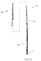
- Figure 15 shows the first window finder 2 connected with a single trip whipstock assembly 100.
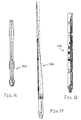
- a milling tool 102, whipstock 104 and anchor packer 106 of the single trip whipstock assembly 100 are shown as enlarged views in Figures 16-18 of the accompanying drawings.
- MWD Measurement While Drilling
- UBHO sub for gyro surveying.
- a bypass valve should preferably be provided.
- the bypass valve will also avoid premature activation of a hydraulically settable window finder.
- the packer is selected to have a higher setting pressure than the window finder activation pressure.
- the well bore 108 is provided with a pre-formed window member 110 (which may have been previously milled whilst in hole) having a Polished Bore Receptacle 112 connected to its uphole end.
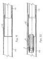
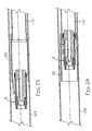
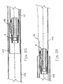
- the window finder 2 is shown in Figures 20-24 being received within the Polished Bore Receptacle 112 whilst arranged with the window engaging member 6 deployed in the extended position. If appropriate, the window finder 2 may be run in hole with the engaging member 6 extended.
- the window finder 2 and associated conveying string may then be run further downhole so as to, for example, locate a whipstock adjacent the window 116.
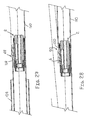
- the downhole end 120 of the window 116 engages the camming portion 50 of the window engaging member 6 and presses said member 6 towards the retracted position.
- the window finder 2 is thereby able to move past the window 116 (see Figure 29 ).
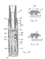
- a third window finder 300 is shown in Figure 30 .
- the third window finder 300 is a modified version of the first window finder 2 and, accordingly, like components are labelled with like reference numerals in the accompanying drawings.
- the principal modification in the third window finder 300 is the provision of a spring biased cylindrical piston 326 which cammingly engages cam surfaces 301, 303 of the window engaging member 306 (see Figure 31 ).
- a flow of well bore fluid through the window finder 300 passes through an orifice member 305 mounted within the bore 334 of the piston 326.
- the orifice member 305 is retained in position within the bore 334 by means of a circlip 307. With sufficient fluid flow, the piston 326 is pressed downhole within the window finder 300 against the uphole bias of a compression spring 309. The downhole movement of the piston 326 generates relative movement between the piston 326 and the camming surfaces 301, 303 of the engaging member 306 and causes the engaging member 306 to be cammed laterally into an extended position (see Figure 31 ). In moving to the extended position, the window engaging member 306 presses on a cylindrical sleeve 311 mounted around the lower part of the window finder 300.
- the cylindrical sleeve 311 is biased in an uphole direction into abutment with the camming portion 50 of the engaging member 6 by means of a second compression string 313.
- the sleeve 311 is cammed downhole by the camming portion 50 against the bias of the compression spring 313. Accordingly, when the rate of flow of well bore fluid through the third window finder 300 is reduced so as to allow the first compression spring 309 to return the piston 326 to its uphole position, the second compression spring 313 tends to press the sleeve 311 against the camming portion 50 so as to cam the engaging member 306 towards the retracted position.
- appropriate O-ring seals 315 are provided on the piston 326.
- the piston 326 and window engaging member 306 are arranged so that, when in the extended position, the engaging member 306 is supported by surfaces 317 of the piston 326 lying perpendicular to the lateral direction of engaging member 6 travel (see Figure 32 ).
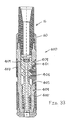
- a fourth window finder 400 is shown in Figure 33 of the accompanying drawings.
- the fourth window finder 400 is essentially identical to the third window finder 300 shown in Figure 30 , principally differing only in the way in which the window engaging member 406 is biased towards the retracted position.
- the fourth window finder 400 uses two compression springs 401, 403 located between the ends of the engaging member 406 and two adjacently located outer cylindrical sleeves 405, 407.
- the outer sleeves 405, 407 are secured in position by means of suitable fasteners (for example, bolts 409).
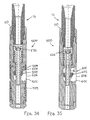
- each modified window finder 500, 600 the window engaging member is pivotally mounted so as to rotate between retracted and extended positions.
- the window engaging member 506, 606 is mounted at its downhole end by means of a pivot 501, 601.
- rotation of the engaging member 506, 606 to the extended position is achieved by pumping well bore fluid through the window finder 500, 600 so as to displace the piston 526, 626 downhole and thereby cause camming members 503, 603 mounted on the piston 526, 626 to press the engaging member 506, 606 laterally outwards.
- the engaging member 506 of the fifth window finder 500 is biased towards the retracted position by means of a spring biased external cylindrical sleeve 509.
- the outward rotation of the engaging member 606 to the extended position is limited by means of a pin and groove arrangement 605, wherein a pin is mounted to either the window finder body or the engaging member 606 and is received within a groove provided in the other of the window finder body and engaging member 606.
- the camming member 603 cooperates with the engaging member 606 so as to cam the engaging member 606 towards the retracted position as the piston 626 is moved uphole.
- the window engaging member may be inverted so that the hook portion 48 faces downhole so as to be engageable with a downhole end of a window.
- a window finder may be provided for engaging with the downhole end of a window rather than the uphole end of a window as hereinbefore described.
Landscapes
- Geology (AREA)
- Life Sciences & Earth Sciences (AREA)
- Engineering & Computer Science (AREA)
- Mining & Mineral Resources (AREA)
- Physics & Mathematics (AREA)
- Environmental & Geological Engineering (AREA)
- Fluid Mechanics (AREA)
- General Life Sciences & Earth Sciences (AREA)
- Geochemistry & Mineralogy (AREA)
- Geophysics (AREA)
- Earth Drilling (AREA)
- Glass Compositions (AREA)
- Electric Double-Layer Capacitors Or The Like (AREA)
- Details Of Measuring And Other Instruments (AREA)
Claims (20)
- Dispositif de fond de trou pour déterminer la profondeur et l'orientation d'une fenêtre dans un trou de forage, le dispositif comprenant : un corps (4) ; et un élément de mise en prise avec une fenêtre (6) monté sur ledit corps (4) de manière à pouvoir être déplacé entre une position rétractée et une position étendue, l'élément de mise en prise avec une fenêtre (6) faisant saillie d'une plus grande distance dudit corps (4) lorsqu'il est dans la position étendue que lorsqu'il est dans la position rétractée, l'élément de mise en prise avec une fenêtre (6) formant un crochet (48) qui peut s'étendre dans une fenêtre de trou de forage lorsque l'élément de mise en prise avec une fenêtre (6) est dans la position étendue pendant une utilisation, le crochet (48) étant adapté pour venir en prise avec une première partie du bord qui définit la fenêtre (116) de manière à ce que, lorsqu'il est pressé contre ledit bord, le crochet tende à coulisser le long du bord de manière à positionner le crochet au centre dans ladite fenêtre à une extrémité (118) de celui-ci avant d'empêcher un mouvement supplémentaire du dispositif de fond de trou dans la direction de pression, l'élément de mise en prise avec une fenêtre (6) comportant également une partie de came (50) adaptée pour venir en prise avec une deuxième partie (120) dudit bord de manière à ce que, lorsque la partie de came (50) est pressée contre ladite deuxième partie (120), l'élément de mise en prise avec une fenêtre (6) soit déplacé vers la position rétractée de manière à permettre un mouvement du dispositif de fond de trou au delà de ladite fenêtre (116), caractérisé en ce que le dispositif comprend des moyens de fixation (26, 42) pour maintenir l'élément de mise en prise avec une fenêtre (6) dans sa position rétractée, les moyens de fixation (42) pouvant être libérés de manière sélective pour permettre à l'élément de mise en prise avec une fenêtre (6) de se déplacer de la position rétractée vers la position étendue.
- Dispositif de fond de trou selon la revendication 1, caractérisé en ce que l'élément de mise en prise avec une fenêtre (6) est monté de manière à pouvoir être déplacé dans son ensemble latéralement vers la position étendue.
- Dispositif de fond de trou selon la revendication 1 ou la revendication 2, caractérisé en ce que des moyens de sollicitation (54) sont prévus pour presser l'élément de mise en prise avec une fenêtre (6) vers la position étendue.
- Dispositif de fond de trou selon l'une quelconque des revendications précédentes, caractérisé en ce que lesdits moyens de fixation comprennent un piston (26) pour déplacer des rails de guidage (46) de l'un de l'élément de mise en prise avec une fenêtre (6) et du corps de dispositif (4) en alignement avec des fentes de guidage (32) prévues dans l'autre de l'élément de mise en prise avec une fenêtre (6) et du corps de dispositif (4).
- Dispositif de fond de trou selon la revendication 4, caractérisé en ce que le piston (26) peut être déplacé par l'application d'une pression hydraulique statique.
- Dispositif de fond de trou selon la revendication 4 ou 5, caractérisé en ce que le piston (26) est fixé au corps de dispositif (4) au moyen d'une goupille de cisaillement (42).
- Dispositif de fond de trou selon l'une quelconque des revendications précédentes, caractérisé en ce que l'élément de mise en prise avec une fenêtre (6) peut être déplacé entre des positions rétractée et étendue au moyen d'une came prévue sur un piston mobile par rapport à l'élément de mise en prise, l'élément de mise en prise avec une fenêtre (6) étant de préférence pourvu d'une came pour coopérer avec la came de piston.
- Dispositif de fond de trou selon la revendication 7, caractérisé en ce que le piston est sollicité par des moyens de sollicitation vers une première position dans laquelle l'élément de mise en prise avec une fenêtre peut se placer dans la position rétractée, le piston pouvant être déplacé contre la sollicitation des moyens de sollicitation, sous l'application d'une pression hydraulique dynamique, vers une deuxième position dans laquelle l'élément de mise en prise avec une fenêtre est déplacé par came vers la position étendue.
- Dispositif de fond de trou selon l'une quelconque de la revendication 7 ou de la revendication 8, caractérisé en ce que l'élément de mise en prise avec une fenêtre est sollicité vers la position rétractée.
- Dispositif de fond de trou selon la revendication 9, caractérisé en ce que l'élément de mise en prise avec une fenêtre est sollicité au moyen d'un élément de sollicitation monté sur le corps de dispositif, l'élément de sollicitation étant sollicité vers une surface de came de l'élément de mise en prise de manière à solliciter l'élément de mise en prise avec une fenêtre vers la position rétractée.
- Dispositif de fond de trou selon l'une quelconque des revendications 7 à 10, caractérisé en ce que l'élément de mise en prise avec une fenêtre est capable de tourner entre les positions rétractée et étendue autour d'un pivot.
- Dispositif de fond de trou selon l'une quelconque des revendications précédentes, caractérisé en ce que des cannelures (18) sont prévues pour fixer la position angulaire du dispositif par rapport à un autre dispositif de fond de trou.
- Dispositif de fond de trou selon l'une quelconque des revendications précédentes, caractérisé en ce que l'élément de mise en prise avec une fenêtre (6) est le seul élément de mise en prise avec une fenêtre.
- Procédé de positionnement d'un outil de déflexion (104) à une position requise par rapport à une fenêtre (116) formée dans le tubage d'un puits, le procédé comprenant : l'extension dans le tubage d'un ensemble d'un outil de déflexion (104) et, situé au-dessous de l'outil de déflexion et en rotation rapide avec celui-ci, d'un dispositif de positionnement ; caractérisé en ce que le dispositif de positionnement est un dispositif de recherche de fenêtre comportant un corps (4) et un élément de mise en prise avec une fenêtre (6) monté dans le corps (4) de manière à pouvoir être déplacé de manière sélective entre une position rétractée et une position étendue, l'élément de mise en prise avec une fenêtre (6) faisant saillie d'une plus grande distance du corps lorsqu'il est dans la position étendue que lorsqu'il est dans la position rétractée, et étant adapté pour s'étendre dans la fenêtre (116) lorsqu'il est dans la position étendue ; le positionnement de l'ensemble de sorte que l'élément de mise en prise avec une fenêtre (6) s'étende dans la fenêtre (116) ; la manipulation de l'ensemble de sorte que l'élément de mise en prise avec une fenêtre (6) coulisse le long du bord du tubage définissant la fenêtre pour positionner l'élément de mise en prise avec une fenêtre au centre dans la fenêtre à une extrémité (118) de celui-ci et positionner de ce fait l'élément de déflexion (104) dans une orientation et à une profondeur connues par rapport à la fenêtre (116) ; et l'abaissement de l'ensemble d'une distance prédéterminée pour positionner l'élément de déflexion (104) à la position requise par rapport à la fenêtre.
- Procédé selon la revendication 14 comprenant l'étape supplémentaire de fixation d'une ancre (106) qui fait partie de l'ensemble après l'actionnement du dispositif de recherche de fenêtre.
- Procédé selon la revendication 14 ou la revendication 15, caractérisé en ce que l'outil de déflexion (104) est un biseau de déflexion.
- Procédé selon la revendication 16, dans lequel l'ensemble est un ensemble de biseau de déflexion à simple effet.
- Procédé de détermination de la profondeur et de l'orientation d'une fenêtre dans un trou de forage selon l'une quelconque de revendications 14 à 17 en utilisant un dispositif selon l'une quelconque des revendications 1 à 13, le procédé comprenant les étapes consistant à étendre ledit dispositif dans un trou de forage ; libérer de manière sélective les moyens de fixation (42) ; étendre l'élément de mise en prise avec une fenêtre (6) dans la fenêtre (116) ; et déplacer le dispositif dans le trou de forage de sorte que le crochet (48) se positionne au centre dans une partie (118), de préférence l'extrémité de haut de trou, de la fenêtre (116) pour arrêter ledit mouvement.
- Procédé selon la revendication 18, caractérisé en ce que le procédé comprend l'étape supplémentaire consistant à déplacer le dispositif de sorte que la partie de came (50) de l'élément de mise en prise avec une fenêtre (6) soit pressée contre le bord définissant la fenêtre et que l'élément de mise en prise avec une fenêtre (6) soit de ce fait déplacé vers la position rétractée de manière à permettre le mouvement du dispositif au-delà de la fenêtre.
- Procédé selon la revendication 19, caractérisé en ce que le procédé comprend en outre l'étape de déplacement du dispositif au-delà de la fenêtre.
Applications Claiming Priority (3)
| Application Number | Priority Date | Filing Date | Title |
|---|---|---|---|
| GB0014146 | 2000-06-09 | ||
| GB0014146A GB2363139B (en) | 2000-06-09 | 2000-06-09 | Downhole window finder and a method of using the same |
| PCT/GB2001/001823 WO2001094745A1 (fr) | 2000-06-09 | 2001-04-24 | Dispositif de localisation de porte de derrick de fond et procede d'utilisation correspondant |
Publications (2)
| Publication Number | Publication Date |
|---|---|
| EP1287227A1 EP1287227A1 (fr) | 2003-03-05 |
| EP1287227B1 true EP1287227B1 (fr) | 2008-10-08 |
Family
ID=9893363
Family Applications (1)
| Application Number | Title | Priority Date | Filing Date |
|---|---|---|---|
| EP01923821A Expired - Lifetime EP1287227B1 (fr) | 2000-06-09 | 2001-04-24 | Dispositif de localisation de porte de derrick de fond et procede d'utilisation correspondant |
Country Status (6)
| Country | Link |
|---|---|
| US (1) | US7331387B2 (fr) |
| EP (1) | EP1287227B1 (fr) |
| CA (1) | CA2411701C (fr) |
| GB (1) | GB2363139B (fr) |
| NO (1) | NO324298B1 (fr) |
| WO (1) | WO2001094745A1 (fr) |
Families Citing this family (18)
| Publication number | Priority date | Publication date | Assignee | Title |
|---|---|---|---|---|
| GB2382369B (en) * | 2001-01-26 | 2003-12-03 | Baker Hughes Inc | A running tool for orienting relative to a casing window |
| US6679329B2 (en) | 2001-01-26 | 2004-01-20 | Baker Hughes Incorporated | Sand barrier for a level 3 multilateral wellbore junction |
| US6848504B2 (en) | 2002-07-26 | 2005-02-01 | Charles G. Brunet | Apparatus and method to complete a multilateral junction |
| US7980307B2 (en) * | 2008-09-10 | 2011-07-19 | Smith International, Inc. | Downhole window finder system |
| US8316937B2 (en) * | 2009-04-02 | 2012-11-27 | Knight Information Systems, Llc | Multi-window lateral well locator/reentry apparatus and method |
| US8069920B2 (en) * | 2009-04-02 | 2011-12-06 | Knight Information Systems, L.L.C. | Lateral well locator and reentry apparatus and method |
| US8905159B2 (en) * | 2009-12-15 | 2014-12-09 | Schlumberger Technology Corporation | Eccentric steering device and methods of directional drilling |
| WO2012012884A1 (fr) * | 2010-07-28 | 2012-02-02 | Packers Plus Energy Services Inc. | Système pour la mise en place d'une colonne perdue latérale dans un puits de forage |
| US9835011B2 (en) | 2013-01-08 | 2017-12-05 | Knight Information Systems, Llc | Multi-window lateral well locator/reentry apparatus and method |
| NO340508B1 (no) * | 2013-11-21 | 2017-05-02 | Qinterra Tech As | Aktiveringsverktøy for forskyving av en komponent i et brønnrør og framgangsmåte for tilpassing av aktiveringsverktøyet |
| WO2016140679A1 (fr) | 2015-03-05 | 2016-09-09 | Halliburton Energy Services, Inc. | Systèmes de distribution d'énergie pour boîtiers coudés réglables |
| WO2016140687A1 (fr) | 2015-03-05 | 2016-09-09 | Halliburton Energy Services, Inc. | Boîtiers coudés réglables avec éléments de support sacrificiels |
| EP3092365B1 (fr) | 2015-03-05 | 2019-11-20 | Halliburton Energy Services Inc. | Mécanismes d'ajustement pour boîtiers coudés réglables |
| EP3092364B1 (fr) | 2015-03-05 | 2019-12-04 | Halliburton Energy Services Inc | Forage directionnel avec des boîtiers coudés réglables |
| US9816322B2 (en) | 2015-03-05 | 2017-11-14 | Halliburton Energy Services, Inc. | Adjustable bent housings with disintegrable sacrificial support members |
| CN107288623B (zh) * | 2017-08-15 | 2020-07-07 | 马鞍山鹏远电子科技有限公司 | 一种新型井下定位装置 |
| US11293243B2 (en) * | 2020-06-29 | 2022-04-05 | Halliburton Energy Services, Inc. | Hydraulic retrieving tool with drifting capabilities |
| CA3225561A1 (fr) * | 2023-01-10 | 2025-04-08 | Rokk Energy Technologies Inc. | Technologies multilaterales pour puits de forage |
Family Cites Families (20)
| Publication number | Priority date | Publication date | Assignee | Title |
|---|---|---|---|---|
| US2766010A (en) * | 1953-03-06 | 1956-10-09 | Hester Mildred Gibbs | Casing whipstocks |
| US3902361A (en) * | 1974-05-28 | 1975-09-02 | Billy Ray Watson | Collar locator |
| US4813486A (en) * | 1987-09-23 | 1989-03-21 | Arrow Oil Tools, Inc. | Retractable slip assembly |
| US5265684A (en) * | 1991-11-27 | 1993-11-30 | Baroid Technology, Inc. | Downhole adjustable stabilizer and method |
| GB9125778D0 (en) | 1991-12-04 | 1992-02-05 | Anderson Charles A | Downhole stabiliser |
| EP0807201B1 (fr) * | 1995-02-03 | 1999-08-18 | Integrated Drilling Services Limited | Appareil de production et de forage a multiples canaux d'evacuation |
| US5785133A (en) * | 1995-08-29 | 1998-07-28 | Tiw Corporation | Multiple lateral hydrocarbon recovery system and method |
| GB2312696B (en) * | 1996-05-01 | 2000-03-29 | Baker Hughes Inc | Selective mono bore diverter system |
| US6283208B1 (en) * | 1997-09-05 | 2001-09-04 | Schlumberger Technology Corp. | Orienting tool and method |
| US6012516A (en) * | 1997-09-05 | 2000-01-11 | Schlumberger Technology Corporation | Deviated borehole drilling assembly |
| US6244340B1 (en) * | 1997-09-24 | 2001-06-12 | Halliburton Energy Services, Inc. | Self-locating reentry system for downhole well completions |
| EP0961008B1 (fr) * | 1998-04-27 | 2006-12-13 | Schlumberger Holdings Limited | Dispositif et procédé pour forer et équiper un puits dévié |
| US6279659B1 (en) * | 1998-10-20 | 2001-08-28 | Weatherford Lamb, Inc. | Assembly and method for providing a means of support and positioning for drilling multi-lateral wells and for reentry therein through a premilled window |
| US6186233B1 (en) * | 1998-11-30 | 2001-02-13 | Weatherford Lamb, Inc. | Down hole assembly and method for forming a down hole window and at least one keyway in communication with the down hole window for use in multilateral wells |
| US6209644B1 (en) * | 1999-03-29 | 2001-04-03 | Weatherford Lamb, Inc. | Assembly and method for forming a seal in a junction of a multilateral well bore |
| WO2000063528A1 (fr) * | 1999-04-19 | 2000-10-26 | Schlumberger Technology Corporation | Deflecteur dual et dispositif d'orientation destines aux completions multilaterales et procede |
| US6315054B1 (en) * | 1999-09-28 | 2001-11-13 | Weatherford Lamb, Inc | Assembly and method for locating lateral wellbores drilled from a main wellbore casing and for guiding and positioning re-entry and completion device in relation to these lateral wellbores |
| US6533040B2 (en) * | 1999-12-03 | 2003-03-18 | Michael Gondouin | Multi-function apparatus for adding a branch well sealed liner and connector to an existing cased well at low cost |
| US6679329B2 (en) * | 2001-01-26 | 2004-01-20 | Baker Hughes Incorporated | Sand barrier for a level 3 multilateral wellbore junction |
| US6568480B2 (en) * | 2001-05-03 | 2003-05-27 | Smith International, Inc. | Orientation and locator system and method of use |
-
2000
- 2000-06-09 GB GB0014146A patent/GB2363139B/en not_active Expired - Fee Related
-
2001
- 2001-04-24 EP EP01923821A patent/EP1287227B1/fr not_active Expired - Lifetime
- 2001-04-24 WO PCT/GB2001/001823 patent/WO2001094745A1/fr not_active Ceased
- 2001-04-24 US US10/297,405 patent/US7331387B2/en not_active Expired - Lifetime
- 2001-04-24 CA CA002411701A patent/CA2411701C/fr not_active Expired - Lifetime
-
2002
- 2002-12-06 NO NO20025886A patent/NO324298B1/no not_active IP Right Cessation
Also Published As
| Publication number | Publication date |
|---|---|
| GB2363139B (en) | 2004-08-18 |
| GB0014146D0 (en) | 2000-08-02 |
| NO324298B1 (no) | 2007-09-17 |
| WO2001094745A1 (fr) | 2001-12-13 |
| US7331387B2 (en) | 2008-02-19 |
| GB2363139A (en) | 2001-12-12 |
| US20030150612A1 (en) | 2003-08-14 |
| CA2411701C (fr) | 2009-07-07 |
| NO20025886D0 (no) | 2002-12-06 |
| NO20025886L (no) | 2003-02-04 |
| CA2411701A1 (fr) | 2001-12-13 |
| EP1287227A1 (fr) | 2003-03-05 |
Similar Documents
| Publication | Publication Date | Title |
|---|---|---|
| EP1287227B1 (fr) | Dispositif de localisation de porte de derrick de fond et procede d'utilisation correspondant | |
| US4153109A (en) | Method and apparatus for anchoring whipstocks in well bores | |
| US7448446B2 (en) | Thru tubing tool and method | |
| US9951573B2 (en) | Whipstock and deflector assembly for multilateral wellbores | |
| US6367552B1 (en) | Hydraulically metered travel joint | |
| US6390198B2 (en) | Method for running two tubing strings into a well | |
| US7377328B2 (en) | Expandable anchor | |
| US6554062B1 (en) | Anchor apparatus and method | |
| US9945197B2 (en) | Tool positioning and latching system | |
| CA2383421C (fr) | Systeme d'orientation et de localisation | |
| EP4438851A2 (fr) | Libération de broyeur actionnée par rfid à partir d'un sifflet déviateur | |
| US9850742B2 (en) | Reclosable sleeve assembly and methods for isolating hydrocarbon production | |
| US6089319A (en) | Whipstock | |
| US9476260B2 (en) | Casing window assembly | |
| GB2032490A (en) | Anchoring Whipstocks in Well Bores | |
| CA1081205A (fr) | Methode et appareil pour l'ancrage des sifflets de deviation dans les trous de forage | |
| AU2016225860B2 (en) | Casing window assembly | |
| GB2411678A (en) | Orienting and locating a well operation in a borehole | |
| GB2374368A (en) | Method for running two tubing strings into a multilateral well | |
| EA037374B1 (ru) | Компоновка окна обсадной колонны |
Legal Events
| Date | Code | Title | Description |
|---|---|---|---|
| PUAI | Public reference made under article 153(3) epc to a published international application that has entered the european phase |
Free format text: ORIGINAL CODE: 0009012 |
|
| 17P | Request for examination filed |
Effective date: 20021206 |
|
| AK | Designated contracting states |
Kind code of ref document: A1 Designated state(s): AT BE CH CY DE DK ES FI FR GB GR IE IT LI LU MC NL PT SE TR |
|
| RBV | Designated contracting states (corrected) |
Designated state(s): AT BE FR NL |
|
| REG | Reference to a national code |
Ref country code: DE Ref legal event code: 8566 |
|
| 17Q | First examination report despatched |
Effective date: 20040614 |
|
| GRAP | Despatch of communication of intention to grant a patent |
Free format text: ORIGINAL CODE: EPIDOSNIGR1 |
|
| RBV | Designated contracting states (corrected) |
Designated state(s): FR NL |
|
| GRAS | Grant fee paid |
Free format text: ORIGINAL CODE: EPIDOSNIGR3 |
|
| GRAA | (expected) grant |
Free format text: ORIGINAL CODE: 0009210 |
|
| AK | Designated contracting states |
Kind code of ref document: B1 Designated state(s): FR NL |
|
| PLBE | No opposition filed within time limit |
Free format text: ORIGINAL CODE: 0009261 |
|
| STAA | Information on the status of an ep patent application or granted ep patent |
Free format text: STATUS: NO OPPOSITION FILED WITHIN TIME LIMIT |
|
| 26N | No opposition filed |
Effective date: 20090709 |
|
| PGFP | Annual fee paid to national office [announced via postgrant information from national office to epo] |
Ref country code: FR Payment date: 20140409 Year of fee payment: 14 |
|
| PGFP | Annual fee paid to national office [announced via postgrant information from national office to epo] |
Ref country code: NL Payment date: 20150409 Year of fee payment: 15 |
|
| REG | Reference to a national code |
Ref country code: FR Ref legal event code: ST Effective date: 20151231 |
|
| PG25 | Lapsed in a contracting state [announced via postgrant information from national office to epo] |
Ref country code: FR Free format text: LAPSE BECAUSE OF NON-PAYMENT OF DUE FEES Effective date: 20150430 |
|
| REG | Reference to a national code |
Ref country code: NL Ref legal event code: MM Effective date: 20160501 |
|
| PG25 | Lapsed in a contracting state [announced via postgrant information from national office to epo] |
Ref country code: NL Free format text: LAPSE BECAUSE OF NON-PAYMENT OF DUE FEES Effective date: 20160501 |