EP1287767A2 - Dispositif de support d'objets - Google Patents
Dispositif de support d'objets Download PDFInfo
- Publication number
- EP1287767A2 EP1287767A2 EP02018773A EP02018773A EP1287767A2 EP 1287767 A2 EP1287767 A2 EP 1287767A2 EP 02018773 A EP02018773 A EP 02018773A EP 02018773 A EP02018773 A EP 02018773A EP 1287767 A2 EP1287767 A2 EP 1287767A2
- Authority
- EP
- European Patent Office
- Prior art keywords
- holders
- arrangement
- attachment
- stud
- aforementioned
- Prior art date
- Legal status (The legal status is an assumption and is not a legal conclusion. Google has not performed a legal analysis and makes no representation as to the accuracy of the status listed.)
- Withdrawn
Links
Images


Classifications
-
- A—HUMAN NECESSITIES
- A47—FURNITURE; DOMESTIC ARTICLES OR APPLIANCES; COFFEE MILLS; SPICE MILLS; SUCTION CLEANERS IN GENERAL
- A47F—SPECIAL FURNITURE, FITTINGS, OR ACCESSORIES FOR SHOPS, STOREHOUSES, BARS, RESTAURANTS OR THE LIKE; PAYING COUNTERS
- A47F5/00—Show stands, hangers, or shelves characterised by their constructional features
- A47F5/08—Show stands, hangers, or shelves characterised by their constructional features secured to the wall, ceiling, or the like; Wall-bracket display devices
- A47F5/0807—Display panels, grids or rods used for suspending merchandise or cards supporting articles; Movable brackets therefor
Definitions
- the present invention relates to an arrangement for supporting objects with the help of slotted holders and bearers that are capable of detachable attachment to one another in pairs, which holders are so arranged as to be secured to a panel.
- Previously disclosed through SE-512 387-C2 in respect of holders intended for supporting objects, is the principle of causing the aforementioned holders to be supported at a mutual distance from one another distributed both vertically and laterally for the purpose, with the help of slot-shaped accommodating openings in the holders, of enabling the introduction of the attachment part of the carrier for the objects in question that it is wished to display, for example in shops and in other places where the display of products is desired.
- the holders in this case are attached to and/or in large panels in the form of sheets with specific centre distances C between the holders.
- the principal object of the present invention is thus to make available an arrangement of the aforementioned kind, in which the aforementioned problems are solved simply and effectively.
- the aforementioned object is achieved by means of an arrangement in accordance with the present invention, which is characterized essentially in that the aforementioned panel is formed by a number of studs, each of which exhibits a row of holes distributed along the longitudinal extent of the respective stud on the front side of the stud, in that secured in the aforementioned holes are holders which, in a previously disclosed fashion, exhibit slot-shaped openings extending across the stud to accommodate matching attachment parts of the carrier, in that each stud is connected to an attachment rail extending along the rear side of the aforementioned stud, and in that the aforementioned attachment rail exhibits an attachment arrangement for the attachment of the aforementioned panel studs to the intended attachment points.
- An arrangement 1 in accordance with the present invention which is arranged for the support of objects 2 of various kinds with the help of slotted holders 3 and carriers 4 that are capable of detachable attachment to one another in pairs, which holders 3 are so arranged as to be attached to a panel 5, 5 1 , 5 2 , exhibits a narrow, elongated panel 5. More specifically, the aforementioned panel is in the form of a number of studs 5, each of which exhibits a row 6 with a number of holes 7 that are uniformly distributed along the front side 5A of each stud, which can exhibit a routed pattern 8.
- each stud 5 is connected to an attachment rail 11 extending along the rear side 5B of the aforementioned stud, which in turn exhibits an attachment arrangement 12 that is arranged for attachment of the aforementioned panel studs 5 at intended desired attachment points I, for example extending vertically along a wall 13.
- FIG. 4 Illustrated in Fig. 4 is an example of a slot-shaped attachment arrangement 12 intended in a previously disclosed fashion to be hooked onto a horizontal carrier rail 14.
- the aforementioned studs 5 are made essentially of surface-treated timber with circular holes 7 arranged in rows and above one another viewed with the studs 5 held vertically as shown in Fig. 7.
- the attachment rail 11 essentially exhibits a U-shaped cross-sectional profile with its base part 11A facing in a direction towards 15 the stud 5 close up to it and attached to the aforementioned stud 5, for example with screws, adhesive, etc.
- the aforementioned holders 3 are so arranged as to be attached either directly to the attachment rail 11 or directly to the stud 5. It is possible to use screws or other attachment means for this purpose.
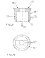
- holders 103 exhibit a number of annular barbs 150 on their cylinder-shaped outside 151 at the insertion end 154 of the essentially circular insertion part 152 of the holder 103.
- the form is essentially circular because it is easy to drill suitable holes for the holders 103 in the intended stud and to cause the attachment-adapted insertion part 152 of the holders to be pressed and/or tapped in place at the opposite end 153 of the holders 103 where the aforementioned slot-shaped accommodating openings 109 are situated.
- the barbs 150 are conical with a reduced cross-sectional profile in the direction of insertion 155 of the holders. The holders 103 are thus pushed in by hand into a matching hole at the intended point of attachment in the stud, or they are tapped in place using a hammer.
- the aforementioned holders 3; 103 consist of a metallic or plastic material and are easy to machine in large series.
- the holders 3 are attached at a mutual distance K, L, F, G, ... from one another and from the ends 5C, 5D of the stud in question and to an intended depth H.
- the aforementioned studs 5 with a holder 3 and an attachment rail 11 can be suspended and, if required, screwed to a wall 13 at desired distances from one another viewed from the side.
- the length of the studs 5 can also be varied.
Landscapes
- Connection Of Plates (AREA)
- Clamps And Clips (AREA)
Applications Claiming Priority (2)
| Application Number | Priority Date | Filing Date | Title |
|---|---|---|---|
| SE0102891 | 2001-08-30 | ||
| SE0102891A SE523662C2 (sv) | 2001-08-30 | 2001-08-30 | Anordning för uppbärning av föremål |
Publications (2)
| Publication Number | Publication Date |
|---|---|
| EP1287767A2 true EP1287767A2 (fr) | 2003-03-05 |
| EP1287767A3 EP1287767A3 (fr) | 2004-01-07 |
Family
ID=20285182
Family Applications (1)
| Application Number | Title | Priority Date | Filing Date |
|---|---|---|---|
| EP02018773A Withdrawn EP1287767A3 (fr) | 2001-08-30 | 2002-08-22 | Dispositif de support d'objets |
Country Status (2)
| Country | Link |
|---|---|
| EP (1) | EP1287767A3 (fr) |
| SE (1) | SE523662C2 (fr) |
Family Cites Families (5)
| Publication number | Priority date | Publication date | Assignee | Title |
|---|---|---|---|---|
| FR2556423B1 (fr) * | 1983-12-09 | 1986-09-19 | Legrand Sa | Accessoire de fixation propre a l'assujettissement d'un quelconque article, par exemple goulotte ou conduit, a un quelconque support, par exemple plaque perforee, montant de chassis ou porte d'armoire, notamment pour appareillage electrique |
| GB2224923B (en) * | 1988-11-19 | 1992-04-15 | Metric Design Limited | A display or storage system |
| NZ248219A (en) * | 1992-07-22 | 1995-06-27 | Rene Wilhelm Crooymans | Shelving support system; column supports with discrete cutouts for extrusions that support a shelf |
| SE512387C2 (sv) * | 1999-02-09 | 2000-03-13 | Samuelsons Inredningar Ab | Anordning vid hållare |
| DE29910251U1 (de) * | 1999-06-11 | 2000-10-19 | Display Partner Gmbh, 63829 Krombach | Warenaufhängungs- und Informationsanordnung für ein vertikale Holme aufweisendes Regalsystem |
-
2001
- 2001-08-30 SE SE0102891A patent/SE523662C2/sv not_active IP Right Cessation
-
2002
- 2002-08-22 EP EP02018773A patent/EP1287767A3/fr not_active Withdrawn
Also Published As
| Publication number | Publication date |
|---|---|
| EP1287767A3 (fr) | 2004-01-07 |
| SE0102891L (sv) | 2003-03-01 |
| SE523662C2 (sv) | 2004-05-04 |
| SE0102891D0 (sv) | 2001-08-30 |
Similar Documents
| Publication | Publication Date | Title |
|---|---|---|
| US6070957A (en) | Device for fastening a support rail on frame legs and mounting panels of a switchgear cabinet | |
| US6202570B1 (en) | Communications equipment relay rack | |
| US5944294A (en) | Mounting device in form of C-clamp mounted space from a wall | |
| US10932593B2 (en) | Organizer set with retention system and method of making same | |
| AU2004304409B2 (en) | Accessory for lifting and bonding wire cable trays | |
| JP3390835B2 (ja) | 壁掛け物品取付け装置 | |
| US20060102569A1 (en) | Tool rack | |
| WO2005107536A3 (fr) | Un système pour tenir les accessoires | |
| US20090194492A1 (en) | Accessory merchandiser | |
| US2833420A (en) | Shelf and bracket assemblage | |
| ATE48298T1 (de) | Tragschiene fuer unterdecken und zubehoer. | |
| US4549712A (en) | Apparatus for mounting a device on a slotted post | |
| US4406104A (en) | Suspended ceiling wall angle | |
| EP3681354B1 (fr) | Un système de rayonnage | |
| US4775054A (en) | Product display system | |
| WO2016051613A1 (fr) | Dispositif de support | |
| EP1287767A2 (fr) | Dispositif de support d'objets | |
| MXPA99006563A (es) | Anaqueles para sostener artículos, especialmente en refrigeradores y soportes que forman estos anaqueles. | |
| EP0043168A1 (fr) | Armoire, rayonnage ou similaire | |
| US11096507B2 (en) | Cash wrap greeting card display | |
| KR100741312B1 (ko) | 천정판 부착용 엠-바의 체결장치 | |
| GB2585269A (en) | Securing Bracket | |
| JPH1122098A (ja) | 野縁受け支持構造 | |
| EP3675690A1 (fr) | Article de suspension | |
| WO2003094672A1 (fr) | Dispositif de montants creux en forme de rail |
Legal Events
| Date | Code | Title | Description |
|---|---|---|---|
| PUAI | Public reference made under article 153(3) epc to a published international application that has entered the european phase |
Free format text: ORIGINAL CODE: 0009012 |
|
| AK | Designated contracting states |
Kind code of ref document: A2 Designated state(s): AT BE BG CH CY CZ DE DK EE ES FI FR GB GR IE IT LI LU MC NL PT SE SK TR Designated state(s): AT BE BG CH CY CZ DE DK EE ES FI FR GB GR IE IT LI LU MC NL PT SE SK TR |
|
| AX | Request for extension of the european patent |
Extension state: AL LT LV MK RO SI |
|
| PUAL | Search report despatched |
Free format text: ORIGINAL CODE: 0009013 |
|
| AK | Designated contracting states |
Kind code of ref document: A3 Designated state(s): AT BE BG CH CY CZ DE DK EE ES FI FR GB GR IE IT LI LU MC NL PT SE SK TR |
|
| AX | Request for extension of the european patent |
Extension state: AL LT LV MK RO SI |
|
| 17P | Request for examination filed |
Effective date: 20040702 |
|
| 17Q | First examination report despatched |
Effective date: 20040812 |
|
| AKX | Designation fees paid |
Designated state(s): AT BE BG CH CY CZ DE DK EE ES FI FR GB GR IE IT LI LU MC NL PT SE SK TR |
|
| GRAP | Despatch of communication of intention to grant a patent |
Free format text: ORIGINAL CODE: EPIDOSNIGR1 |
|
| STAA | Information on the status of an ep patent application or granted ep patent |
Free format text: STATUS: THE APPLICATION IS DEEMED TO BE WITHDRAWN |
|
| 18D | Application deemed to be withdrawn |
Effective date: 20050604 |