EP1287878A2 - Appareil de traitement des materiaux - Google Patents
Appareil de traitement des materiaux Download PDFInfo
- Publication number
- EP1287878A2 EP1287878A2 EP02018534A EP02018534A EP1287878A2 EP 1287878 A2 EP1287878 A2 EP 1287878A2 EP 02018534 A EP02018534 A EP 02018534A EP 02018534 A EP02018534 A EP 02018534A EP 1287878 A2 EP1287878 A2 EP 1287878A2
- Authority
- EP
- European Patent Office
- Prior art keywords
- rotor
- container
- insert
- carrier
- stator
- Prior art date
- Legal status (The legal status is an assumption and is not a legal conclusion. Google has not performed a legal analysis and makes no representation as to the accuracy of the status listed.)
- Granted
Links
Images



Classifications
-
- B—PERFORMING OPERATIONS; TRANSPORTING
- B01—PHYSICAL OR CHEMICAL PROCESSES OR APPARATUS IN GENERAL
- B01F—MIXING, e.g. DISSOLVING, EMULSIFYING OR DISPERSING
- B01F27/00—Mixers with rotary stirring devices in fixed receptacles; Kneaders
- B01F27/27—Mixers with stator-rotor systems, e.g. with intermeshing teeth or cylinders or having orifices
- B01F27/272—Mixers with stator-rotor systems, e.g. with intermeshing teeth or cylinders or having orifices with means for moving the materials to be mixed axially between the surfaces of the rotor and the stator, e.g. the stator rotor system formed by conical or cylindrical surfaces
-
- B—PERFORMING OPERATIONS; TRANSPORTING
- B01—PHYSICAL OR CHEMICAL PROCESSES OR APPARATUS IN GENERAL
- B01F—MIXING, e.g. DISSOLVING, EMULSIFYING OR DISPERSING
- B01F27/00—Mixers with rotary stirring devices in fixed receptacles; Kneaders
- B01F27/27—Mixers with stator-rotor systems, e.g. with intermeshing teeth or cylinders or having orifices
- B01F27/272—Mixers with stator-rotor systems, e.g. with intermeshing teeth or cylinders or having orifices with means for moving the materials to be mixed axially between the surfaces of the rotor and the stator, e.g. the stator rotor system formed by conical or cylindrical surfaces
- B01F27/2723—Mixers with stator-rotor systems, e.g. with intermeshing teeth or cylinders or having orifices with means for moving the materials to be mixed axially between the surfaces of the rotor and the stator, e.g. the stator rotor system formed by conical or cylindrical surfaces the surfaces having a conical shape
-
- B—PERFORMING OPERATIONS; TRANSPORTING
- B01—PHYSICAL OR CHEMICAL PROCESSES OR APPARATUS IN GENERAL
- B01F—MIXING, e.g. DISSOLVING, EMULSIFYING OR DISPERSING
- B01F27/00—Mixers with rotary stirring devices in fixed receptacles; Kneaders
- B01F27/80—Mixers with rotary stirring devices in fixed receptacles; Kneaders with stirrers rotating about a substantially vertical axis
- B01F27/805—Mixers with rotary stirring devices in fixed receptacles; Kneaders with stirrers rotating about a substantially vertical axis wherein the stirrers or the receptacles are moved in order to bring them into operative position; Means for fixing the receptacle
-
- B—PERFORMING OPERATIONS; TRANSPORTING
- B01—PHYSICAL OR CHEMICAL PROCESSES OR APPARATUS IN GENERAL
- B01F—MIXING, e.g. DISSOLVING, EMULSIFYING OR DISPERSING
- B01F35/00—Accessories for mixers; Auxiliary operations or auxiliary devices; Parts or details of general application
- B01F35/10—Maintenance of mixers
-
- B—PERFORMING OPERATIONS; TRANSPORTING
- B01—PHYSICAL OR CHEMICAL PROCESSES OR APPARATUS IN GENERAL
- B01F—MIXING, e.g. DISSOLVING, EMULSIFYING OR DISPERSING
- B01F35/00—Accessories for mixers; Auxiliary operations or auxiliary devices; Parts or details of general application
- B01F35/71—Feed mechanisms
- B01F35/717—Feed mechanisms characterised by the means for feeding the components to the mixer
- B01F35/7173—Feed mechanisms characterised by the means for feeding the components to the mixer using gravity, e.g. from a hopper
-
- B—PERFORMING OPERATIONS; TRANSPORTING
- B01—PHYSICAL OR CHEMICAL PROCESSES OR APPARATUS IN GENERAL
- B01F—MIXING, e.g. DISSOLVING, EMULSIFYING OR DISPERSING
- B01F35/00—Accessories for mixers; Auxiliary operations or auxiliary devices; Parts or details of general application
- B01F35/71—Feed mechanisms
- B01F35/717—Feed mechanisms characterised by the means for feeding the components to the mixer
- B01F35/7173—Feed mechanisms characterised by the means for feeding the components to the mixer using gravity, e.g. from a hopper
- B01F35/71731—Feed mechanisms characterised by the means for feeding the components to the mixer using gravity, e.g. from a hopper using a hopper
-
- D—TEXTILES; PAPER
- D21—PAPER-MAKING; PRODUCTION OF CELLULOSE
- D21D—TREATMENT OF THE MATERIALS BEFORE PASSING TO THE PAPER-MAKING MACHINE
- D21D1/00—Methods of beating or refining; Beaters of the Hollander type
- D21D1/004—Methods of beating or refining including disperging or deflaking
- D21D1/006—Disc mills
-
- B—PERFORMING OPERATIONS; TRANSPORTING
- B01—PHYSICAL OR CHEMICAL PROCESSES OR APPARATUS IN GENERAL
- B01F—MIXING, e.g. DISSOLVING, EMULSIFYING OR DISPERSING
- B01F27/00—Mixers with rotary stirring devices in fixed receptacles; Kneaders
- B01F27/05—Stirrers
- B01F27/051—Stirrers characterised by their elements, materials or mechanical properties
- B01F27/053—Stirrers characterised by their elements, materials or mechanical properties characterised by their materials
- B01F27/0531—Stirrers characterised by their elements, materials or mechanical properties characterised by their materials with particular surface characteristics, e.g. coated or rough
-
- B—PERFORMING OPERATIONS; TRANSPORTING
- B01—PHYSICAL OR CHEMICAL PROCESSES OR APPARATUS IN GENERAL
- B01F—MIXING, e.g. DISSOLVING, EMULSIFYING OR DISPERSING
- B01F27/00—Mixers with rotary stirring devices in fixed receptacles; Kneaders
- B01F27/27—Mixers with stator-rotor systems, e.g. with intermeshing teeth or cylinders or having orifices
- B01F27/272—Mixers with stator-rotor systems, e.g. with intermeshing teeth or cylinders or having orifices with means for moving the materials to be mixed axially between the surfaces of the rotor and the stator, e.g. the stator rotor system formed by conical or cylindrical surfaces
- B01F27/2721—Mixers with stator-rotor systems, e.g. with intermeshing teeth or cylinders or having orifices with means for moving the materials to be mixed axially between the surfaces of the rotor and the stator, e.g. the stator rotor system formed by conical or cylindrical surfaces provided with intermeshing elements
Definitions
- the invention relates to a device for processing materials, especially for mixing, kneading, fibrillating, grinding and unlocking, with a container containing a vertical Container chamber with a product inlet located above, a stator arranged around a vertical axis concentric sprockets and a rotor with multiple arms, have the teeth which are adjacent between the teeth Sprockets grip.
- the rotor arm and the container space located above the standing arranged Device enable a permanent material transfer of inside out and ensure a multiple working through dry and / or highly viscous substances, so that the device for intensive mixing, kneading, fibrillation, digestion and Similar processes important for industrial production is outstanding.
- the standing arrangement of the housing facilitates the falling back of the goods from the periphery against the middle of the device.
- the invention is based on the object, a device of mentioned type in the sense of improving the product further education.
- the solution of this object is achieved according to the invention in the Claim 1 specified characteristics.
- a guide whose centric Funnel opening has a smaller diameter than the Rotor.
- the funnel directs this from the top to the stator / rotor funnel moving material to the center of the container and thus keeps the good in the effective range of the tools. It also ensures that the goods near the axis in the Effective range of tools reaches where it is on the inner cone of the Stators working through the teeth of stator and rotor is moved outwards.
- the hopper guides the product so in the region close to the axis of the device in the effective range of Device.
- the funnel opening extends in the vertical direction into the rotor, that is to say in that area, that of the rotor arms is circumscribed. This means that the inner Opening of the funnel is lower than the upper edges of the Arms of the rotor.
- the hopper has an outer surface, the less is steep than the inner surface.
- the outer surface or lower surface of the funnel causes in cooperation with the Internal taper surface of the stator forming an annulus, in which stagnates the outward-pressing product. In connection This product congestion is followed by product expansion due to the then increasing diameter.
- Such a design of the umpire promotes the redistribution and mixing of the Material in the effective range of the tools.
- a preferred embodiment of the invention provides that the Rotor has a towering from a hub stub shaft, which carries a feed screw.
- the feed screw promotes that Product on its way from top to bottom and generates one additional pressure in the central area of the container.
- the feed screw is particularly suitable for processing difficult-flowing Products and tougher pastes.
- the diameter of the feed screw should be expediently slightly larger than that Diameter of the funnel opening.
- the device according to the invention is also suitable for wet milling of materials. Made by the cooperating sprockets a Vorenergyeintrag in the introduced from above into the container Material with simultaneous heat dissipation through the Casing.
- the Container with a bottom wall finished, in which a Recording for a the carrier wheels supporting the sprockets Stators is located.
- the carrier insert is removable in the receptacle arranged.
- the carrier insert for the purpose of cleaning or maintenance can the carrier insert in its entirety towards the container interior be removed from the bottom wall, after previously the rotor was removed.
- the stator can then be dismantled and it is available for cleaning, overhaul or maintenance. It is not necessary to disassemble the entire container. Rather, the container must only be opened, to gain access to the tray. this happens by removing a lid of the container.
- the bottom wall is integral part of the container and does not need to be removed too become.
- stator with carrier insert and sprockets to replace and replace with a new stator, For example, if the sprockets worn or damaged are.
- the sprockets on the carrier insert can be removed be attached, with each individual ring gear of the stator can be removed from the carrier body and replaced.
- each arm of the rotor from a carrier strip and a so Matching toothed rack made of carbide.
- the carrier strip and the rack grasp fit, i. a form fit, into each other, either the carrier strip or the Rack the encompassing part and the other component represents the inner part of the Caribbeangriffs.
- carbide is a brittle Material that has low resistance to tensile stresses and has bending stresses.
- By the invention is achieved that in the rack no major tensile or bending stresses occur. Such stresses occur only in the carrier strip on, which consist of a steel of high tensile strength can.
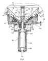
- the device comprises a container 10, for example has a diameter of 600 mm and standing upright a column 100 is mounted.
- the column is 100 mounted on a pedestal 101, which with bearing blocks 102 on standing on the ground.
- podium 101 On podium 101 are two electric motors 103, 104 mounted with vertical axes. Every electric motor drives a pulley 105, 106 inside the pedestal 101 is arranged.
- the pulleys 105, 106 over drive Drive belt 107, 108 a pulley 109, with the in the Column 100 mounted shaft of the device is connected.
- the container 10 has an upper container part 110 which abuts is closed at its upper end with a lid 111. At the lower end of the container part 110 includes a in Side view trapezoidal transition wall 15 at, in a Bottom wall 11 opens. Below the bottom wall is a Blocking liquid housing 112 to which a supply line and a discharge line for barrier liquid is connected.
- the Barrier liquid housing 112 is supported by column 100.
- the container 10 is supported by vertical posts 113, whose lower ends are fixed on the pedestal 101 and the at wear rubber bumper 114 at its upper end.
- the container part 110 has a rectangular - or square - plan. Corner regions 120 are formed, which are rounded and each have an angle of 90 degrees, and straight edge portions 121 that the Connect corner areas.
- the container part 110 is with the truncated pyramid-shaped lower part 130 detachably connected via a flange 131.
- power clamp 132 To the Holding the flange connection 131 are power clamp 132, which can be opened to dismantle the container.
- an overflow 134 is provided on the lower part 130 .
- the container lid 111 On the container lid 111 is centrally located a product inlet 136, through which the product to be processed vertically in the container 10 is input. There are also other inlet ports 137 provided filled by the additives can be. Finally, the lid 111 is still a show opening 135 attached. An access opening is with an in Cover 111 arranged door 138 closed (Fig. 2).
- Fig. 3 the column 100 is passing through it Shaft 12 shown.
- the shaft is with bearings 150, 151 in the Pillar 100 stored.
- the passage of the shaft 12 through the bottom wall 11 is sealed by a seal 22.
- the seal 22 has an inlet 152 and an outlet 153 for sealing fluid on.
- a channel 154 extends to a terminal 155 for the emptying. Through the channel 154 becomes liquid, which is the lowest point of the container space 50 drops, discharged from the container space.
- the bottom wall 11 a circumferential upstanding edge 14 on which the oblique transition wall 15 of the container 10 is attached.
- the Bottom wall 11 defines together with its edge 14 an annular Recording 16, in which an annular stator 17 is arranged is.
- the stator 17 has an inner cone or inner pyramid trained work surface 18.
- Half the ring cross-section of the Stator 17 is generally in the shape of a right triangle, wherein the working surface 18 forms the hypotenuse.
- the stator 17 consists of an annular support insert 19, fitting in the receptacle 16 is included, and several along the work surface 18 arranged sprockets 20th to the inside the receptacle 16 is bounded by an inner ring insert 21, the sealed with the seal 22 shaft passage the shaft 12 forms.
- the carrier insert 19 At the outer periphery is the carrier insert 19 with an annular seal 23 against the peripheral wall the receptacle 16 sealed.
- the Carrier insert with two annular seals 24, 24 'and 25 against the receptacle 16 inwardly bounding inner ring insert 21 sealed. This will prevent that the mass to be treated penetrates behind the carrier insert 19.
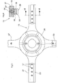
- the rotor 13 has a shaft 26 mounted on the hub 26 and a plurality of radially projecting arms 27 on.
- the arms 27 carry downwardly directed teeth 29, which with teeth 28 of the sprockets 20 of the stator.
- the teeth 28 are from each of the sprockets 20 upwards.
- the teeth 29 of the rotor 13 engage in the tooth spaces between the sprockets 20 of the Stators 17. In the circumferential direction are the teeth 28 of each Sprocket 20 spaced.
- the teeth 28 and 29 are made of wear-resistant material, in particular of hard metal.
- each arm 27 of the rotor 13 a carrier strip 53 of generally U-shaped cross section.
- the carrier strip 53 includes on its oblique bottom a longitudinal groove 54 of rectangular cross-section, in which a Rack 55 is sitting.
- the carrier strip 53 is made of high-strength Steel, while the rack 55 is made of hard metal. Of the Back of the rack 55 fills the groove 54 completely with closer Fit.
- the teeth 29 are located at the out of the groove 54th outstanding part of the rack 55.
- the rack 55 is fixed with screws 56, the through holes 57 of the support bar 53 inserted therethrough are and their threads in a threaded insert 58, which in the Rack 55 is sunk, are screwed.
- the threaded insert 58 is made of steel and is soldered into the rack 55. By loosening the screws 56, evenly spaced are provided along an arm 27, the Rack 55 are dismantled.
- the outermost ring 30a which the adjacent inner support ring 30th holds, is made of stainless steel and is formed without teeth. He is held by a screw on the carrier insert 19. The outer ring 30a thus forms the blocking element for all carrier rings 30.
- the carrier insert 19 can be removed from the receptacle 16 become. This is done by (not shown) pressing screws, screwed into threaded holes 60 of the bottom wall 11 and against the underside of the carrier insert 19 to press. Overall, for example, four threaded holes 60th arranged evenly distributed in the bottom wall 11 for pressing screws. By turning the push-in screws evenly the carrier insert 19 is pushed up into the container space 50. Before this happens, of course, the rotor 13 must be removed. This is done by loosening the screw 61, the rotor 13th on the shaft 12 holds. To gain access to the screw 61, is the plug 41 from the stub shaft 40th unscrewed.
- each individual ring gear 20 can be detached from the carrier insert 19 become.
- each ring gear 20 is inside the carrier insert a threaded bore 68 assigned (Fig. 3), in the a push-in screw sits.
- the push screws are from the bottom the carrier insert 19 is accessible for turning and they can be turned to the respective sprocket 20 off to push out the relevant recess of the carrier insert 19. It is thus possible, each of the sprockets 20 individually replaced.
- Serve screws 70 through the bottom wall 11 therethrough are screwed into the carrier insert 19.
- the retaining screws 70 can be loosened.
- a hopper 34 is at a distance mounted by the transition wall 15.
- the hopper 34 has a funnel-shaped inner surface 35, which in a funnel opening 36 opens at the lower end of the funnel.
- the funnel opening 36 projects into the limited by the arms 27 of the rotor Space from the top in and it has a smaller diameter as the rotor 13.
- the funnel opening 36 concentrated the stuffing from the top into the container and nach Kohlende material to the area of the hub 26, ie to the middle area. There The material enters between the arms 27 of the rotor 13 and passes in the tooth area.
- the hopper 34 has an outer surface 37, the less is steep than the inner surface 35. This has the funnel 34 an increasing diameter with increasing diameter.
- the Outer surface 37 forms together with the transition surface 33 a Annular gap 38 in extension of the arms 27 of the rotor 13.
- the Height of the annular gap 38 decreases towards the outside.
- the hub 26 is in extension of the shaft 12 with a towering Stub shaft 40 provided, which is tubular and with a closure 41 is closed.
- the stub shaft 40 carries a feed screw 42 of one to two courses.
- the feed screw promotes upon rotation of the driven shaft 12 in Direction from top to bottom, so the hub 26 out.
- the diameter the feed screw 42 is slightly larger than the diameter the funnel opening 36.
- the feed screw 42 generates a increased pressure in the center, ie around the rotor 13 around.
Landscapes
- Chemical & Material Sciences (AREA)
- Chemical Kinetics & Catalysis (AREA)
- Mixers Of The Rotary Stirring Type (AREA)
- Filling Or Emptying Of Bunkers, Hoppers, And Tanks (AREA)
- Disintegrating Or Milling (AREA)
- Electrical Discharge Machining, Electrochemical Machining, And Combined Machining (AREA)
- Threshing Machine Elements (AREA)
- Crushing And Pulverization Processes (AREA)
Applications Claiming Priority (6)
| Application Number | Priority Date | Filing Date | Title |
|---|---|---|---|
| DE20114253U | 2001-08-29 | ||
| DE20114250U DE20114250U1 (de) | 2001-08-29 | 2001-08-29 | Vorrichtung zur Bearbeitung von Materialien |
| DE20114253U DE20114253U1 (de) | 2001-08-29 | 2001-08-29 | Vorrichtung zur Bearbeitung von Materialien |
| DE20114250U | 2001-08-29 | ||
| DE20114251U DE20114251U1 (de) | 2001-08-29 | 2001-08-29 | Vorrichtung zur Bearbeitung von Materialien |
| DE20114251U | 2001-08-29 |
Publications (3)
| Publication Number | Publication Date |
|---|---|
| EP1287878A2 true EP1287878A2 (fr) | 2003-03-05 |
| EP1287878A3 EP1287878A3 (fr) | 2003-08-13 |
| EP1287878B1 EP1287878B1 (fr) | 2005-08-10 |
Family
ID=27219614
Family Applications (1)
| Application Number | Title | Priority Date | Filing Date |
|---|---|---|---|
| EP02018534A Expired - Lifetime EP1287878B1 (fr) | 2001-08-29 | 2002-08-17 | Appareil de traitement des materiaux |
Country Status (5)
| Country | Link |
|---|---|
| US (1) | US6883737B2 (fr) |
| EP (1) | EP1287878B1 (fr) |
| JP (1) | JP2003159521A (fr) |
| AT (1) | ATE301495T1 (fr) |
| DE (1) | DE50203865D1 (fr) |
Cited By (5)
| Publication number | Priority date | Publication date | Assignee | Title |
|---|---|---|---|---|
| DE102006043498A1 (de) * | 2006-09-12 | 2008-03-27 | Artur Wiegand | Dispergiermaschine und deren Verwendung für die Herstellung von Pulvermischungen |
| EP2977510A1 (fr) | 2014-07-22 | 2016-01-27 | PGA Putz-Granitzer-Anlagenbau Gesellschaft m.b.H. | Dispositif destine a la preparation de matiere |
| CN107913782A (zh) * | 2018-01-09 | 2018-04-17 | 安徽妙奇树生物科技有限公司 | 一种蔬果酵素生产用粉碎装置 |
| CN108295935A (zh) * | 2018-01-18 | 2018-07-20 | 钟凤娣 | 一种畜牧业用饲料粉末化研磨设备 |
| CN110126232A (zh) * | 2019-04-22 | 2019-08-16 | 安徽信睦信息科技有限公司 | 一种具备节能结构的捏合机 |
Families Citing this family (23)
| Publication number | Priority date | Publication date | Assignee | Title |
|---|---|---|---|---|
| US7890852B2 (en) | 2003-06-26 | 2011-02-15 | International Business Machines Corporation | Rich text handling for a web application |
| FI123269B (fi) * | 2010-07-02 | 2013-01-31 | Haarla Oy | Menetelmä ja järjestely |
| CN103920559A (zh) * | 2014-03-27 | 2014-07-16 | 安徽蒂王集团食品有限公司 | 一种新型的贮料斗 |
| JP7049793B2 (ja) * | 2017-09-29 | 2022-04-07 | 株式会社明治 | 微粒化装置 |
| CN113166427A (zh) | 2018-10-05 | 2021-07-23 | 洛科威国际有限公司 | 生产氧化木质素的方法 |
| EP4127344A1 (fr) | 2020-04-03 | 2023-02-08 | Rockwool A/S | Système de façade et élément d'isolation pour un système de façade |
| WO2021197627A1 (fr) | 2020-04-03 | 2021-10-07 | Rockwool International A/S | Procédé de fabrication de produits à base de fibres vitreuses synthétiques |
| US11690332B2 (en) | 2020-04-03 | 2023-07-04 | Rockwool A/S | Method of growing plants |
| EP4126784A1 (fr) | 2020-04-03 | 2023-02-08 | Rockwool A/S | Produits d'isolation |
| FI4342862T3 (fi) | 2020-04-03 | 2025-12-18 | Rockwool As | Vesipitoinen sideainekoostumus |
| CA3176163A1 (fr) | 2020-04-03 | 2021-10-07 | Rockwool A/S | Systeme de toiture et element d'isolation pour un toit plat ou un toit incline plat |
| US20230151042A1 (en) | 2020-04-03 | 2023-05-18 | Rockwool A/S | Method for producing oxidized lignins and system for producing oxidized lignins |
| CN115698430A (zh) | 2020-04-03 | 2023-02-03 | 洛科威有限公司 | 具有包含木质素类黏合剂的减震垫的体育场 |
| WO2021197633A1 (fr) | 2020-04-03 | 2021-10-07 | Rockwool International A/S | Système de toit |
| WO2021197624A1 (fr) | 2020-04-03 | 2021-10-07 | Rockwool International A/S | Liant à l'état solide |
| US20230175178A1 (en) | 2020-04-03 | 2023-06-08 | Rockwool A/S | Low chloride mineral wool product |
| CN120039022A (zh) | 2020-04-03 | 2025-05-27 | 洛科威有限公司 | 声学产品 |
| CA3174401A1 (fr) | 2020-04-03 | 2021-10-07 | Daan De Kubber | Procede de drainage d'eau |
| WO2021197629A1 (fr) | 2020-04-03 | 2021-10-07 | Rockwool International A/S | Procédé de production de lignines oxydées et système de production de lignines oxydées |
| ES3048132T3 (en) | 2020-04-03 | 2025-12-09 | Rockwool As | High temperature low emitting mineral wool product |
| WO2021197631A1 (fr) | 2020-04-03 | 2021-10-07 | Rockwool International A/S | Procédé de culture de plantes |
| JP2024508589A (ja) | 2020-12-30 | 2024-02-28 | ロックウール アクティーゼルスカブ | 断熱製品 |
| CN114632439A (zh) * | 2022-05-12 | 2022-06-17 | 山东海普欧环保设备科技有限公司 | 一种污泥活性炭生产用自动混料设备 |
Family Cites Families (6)
| Publication number | Priority date | Publication date | Assignee | Title |
|---|---|---|---|---|
| US1794972A (en) * | 1928-07-24 | 1931-03-03 | Frank M Mayer | Grinding mill for grains |
| US3283792A (en) * | 1963-12-16 | 1966-11-08 | Matthew J Thomas | Portable mill |
| CH485479A (de) * | 1968-09-05 | 1970-02-15 | Supraton Bruchmann & Zucker Kg | Vorrichtung zur Herstellung von Dispersionen oder Lösungen |
| CA998662A (en) * | 1974-05-10 | 1976-10-19 | Hiroyuki Iwako | Continuous mixing machine for moistening powdered material |
| DE3641413C1 (en) * | 1986-12-04 | 1988-08-18 | Cavitron V Hagen & Funke Gmbh | Apparatus for processing materials |
| JP2945809B2 (ja) * | 1992-03-13 | 1999-09-06 | アイン株式会社 | プラスチック材からの塗膜剥離,またはプラスチック材を含む粉体材料の粉砕・造粒装置 |
-
2002
- 2002-08-17 EP EP02018534A patent/EP1287878B1/fr not_active Expired - Lifetime
- 2002-08-17 DE DE50203865T patent/DE50203865D1/de not_active Expired - Lifetime
- 2002-08-17 AT AT02018534T patent/ATE301495T1/de not_active IP Right Cessation
- 2002-08-23 US US10/226,338 patent/US6883737B2/en not_active Expired - Fee Related
- 2002-08-29 JP JP2002250108A patent/JP2003159521A/ja active Pending
Cited By (8)
| Publication number | Priority date | Publication date | Assignee | Title |
|---|---|---|---|---|
| DE102006043498A1 (de) * | 2006-09-12 | 2008-03-27 | Artur Wiegand | Dispergiermaschine und deren Verwendung für die Herstellung von Pulvermischungen |
| EP2977510A1 (fr) | 2014-07-22 | 2016-01-27 | PGA Putz-Granitzer-Anlagenbau Gesellschaft m.b.H. | Dispositif destine a la preparation de matiere |
| AT516085A1 (de) * | 2014-07-22 | 2016-02-15 | Pga Putz Granitzer Anlagenbau Ges M B H | Vorrichtung zum Aufbereiten von Stoff |
| AT516085B1 (de) * | 2014-07-22 | 2016-08-15 | Pga Putz-Granitzer-Anlagenbau Ges M B H | Vorrichtung zum Aufbereiten von Stoff |
| US10266988B2 (en) | 2014-07-22 | 2019-04-23 | PGA Putz-Granitzer-Anlagenbau Gesellschaft m.b.H. | Device for preparing a substance |
| CN107913782A (zh) * | 2018-01-09 | 2018-04-17 | 安徽妙奇树生物科技有限公司 | 一种蔬果酵素生产用粉碎装置 |
| CN108295935A (zh) * | 2018-01-18 | 2018-07-20 | 钟凤娣 | 一种畜牧业用饲料粉末化研磨设备 |
| CN110126232A (zh) * | 2019-04-22 | 2019-08-16 | 安徽信睦信息科技有限公司 | 一种具备节能结构的捏合机 |
Also Published As
| Publication number | Publication date |
|---|---|
| ATE301495T1 (de) | 2005-08-15 |
| DE50203865D1 (de) | 2005-09-15 |
| EP1287878B1 (fr) | 2005-08-10 |
| JP2003159521A (ja) | 2003-06-03 |
| US20030042344A1 (en) | 2003-03-06 |
| US6883737B2 (en) | 2005-04-26 |
| EP1287878A3 (fr) | 2003-08-13 |
Similar Documents
| Publication | Publication Date | Title |
|---|---|---|
| EP1287878B1 (fr) | Appareil de traitement des materiaux | |
| EP0329662B1 (fr) | Dispositif de traitement de matieres plastiques | |
| EP0146852A1 (fr) | Broyeur agitateur | |
| DE3617175C2 (de) | Einrichtung zum Passieren, insbesondere Granulieren und/oder Sieben eines Gutes | |
| EP0700721B1 (fr) | Broyeur agitateur | |
| DE69105169T2 (de) | Feinmahlanlage. | |
| DE2247518B2 (de) | Mischer | |
| DE19835555B4 (de) | Verfahren und Vorrichtung zum Nassmahlen und Dispergieren von Feststoffpartikeln in Flüssigkeiten | |
| DE3015631A1 (de) | Ruehrwerksmuehle | |
| EP0448100A1 (fr) | Broyeur-mélangeur | |
| DE2725333A1 (de) | Knollenbrecher zum anschluss an ein reaktionsgefaess | |
| DE3641413C1 (en) | Apparatus for processing materials | |
| EP4032615A1 (fr) | Broyeur agitateur | |
| CH664928A5 (de) | Verfahren und schneckenpresse zum verdichten und entwaessern von festmaterial. | |
| DE2043608C2 (de) | Tellermischer | |
| DE1912501U (de) | Vorrichtung zur beseitigung von abfaellen. | |
| DE10231366B4 (de) | Vorrichtung zur Bearbeitung von Materialien | |
| DE3444912C2 (de) | Vorrichtung zum Behandeln pumpfähiger Materialien | |
| DE102011102073B4 (de) | Vorrichtung zum Entfernen von Siebgut aus einer Flüssigkeit | |
| DE3406648A1 (de) | Mischmaschine fuer kontinuierliche mischverfahren | |
| DE1960605A1 (de) | Foerdereinrichtung mit Foerderschnecke | |
| DE2124701A1 (de) | Feinmahl werk | |
| EP2203254B1 (fr) | Broyeur vibrant et procédé de nettoyage de broyeurs vibrants | |
| EP4108935A1 (fr) | Bague coupante d'une pompe pour liquide chargé de solide | |
| EP0203316B1 (fr) | Procédé et dispositif pour séparer des métaux et d'autres matières solides de liquides |
Legal Events
| Date | Code | Title | Description |
|---|---|---|---|
| PUAI | Public reference made under article 153(3) epc to a published international application that has entered the european phase |
Free format text: ORIGINAL CODE: 0009012 |
|
| AK | Designated contracting states |
Kind code of ref document: A2 Designated state(s): AT BE BG CH CY CZ DE DK EE ES FI FR GB GR IE IT LI LU MC NL PT SE SK TR Designated state(s): AT BE BG CH CY CZ DE DK EE ES FI FR GB GR IE IT LI LU MC NL PT SE SK TR |
|
| AX | Request for extension of the european patent |
Extension state: AL LT LV MK RO SI |
|
| PUAL | Search report despatched |
Free format text: ORIGINAL CODE: 0009013 |
|
| AK | Designated contracting states |
Designated state(s): AT BE BG CH CY CZ DE DK EE ES FI FR GB GR IE IT LI LU MC NL PT SE SK TR |
|
| AX | Request for extension of the european patent |
Extension state: AL LT LV MK RO SI |
|
| RIC1 | Information provided on ipc code assigned before grant |
Ipc: 7B 01F 15/00 B Ipc: 7B 01F 15/02 B Ipc: 7B 01F 7/00 B Ipc: 7B 01F 7/16 A |
|
| 17P | Request for examination filed |
Effective date: 20040211 |
|
| AKX | Designation fees paid |
Designated state(s): AT BE BG CH CY CZ DE DK EE ES FI FR GB GR IE IT LI LU MC NL PT SE SK TR |
|
| 17Q | First examination report despatched |
Effective date: 20040701 |
|
| GRAP | Despatch of communication of intention to grant a patent |
Free format text: ORIGINAL CODE: EPIDOSNIGR1 |
|
| GRAS | Grant fee paid |
Free format text: ORIGINAL CODE: EPIDOSNIGR3 |
|
| GRAA | (expected) grant |
Free format text: ORIGINAL CODE: 0009210 |
|
| AK | Designated contracting states |
Kind code of ref document: B1 Designated state(s): AT BE BG CH CY CZ DE DK EE ES FI FR GB GR IE IT LI LU MC NL PT SE SK TR |
|
| PG25 | Lapsed in a contracting state [announced via postgrant information from national office to epo] |
Ref country code: EE Free format text: LAPSE BECAUSE OF FAILURE TO SUBMIT A TRANSLATION OF THE DESCRIPTION OR TO PAY THE FEE WITHIN THE PRESCRIBED TIME-LIMIT Effective date: 20050810 Ref country code: IE Free format text: LAPSE BECAUSE OF FAILURE TO SUBMIT A TRANSLATION OF THE DESCRIPTION OR TO PAY THE FEE WITHIN THE PRESCRIBED TIME-LIMIT Effective date: 20050810 Ref country code: IT Free format text: LAPSE BECAUSE OF FAILURE TO SUBMIT A TRANSLATION OF THE DESCRIPTION OR TO PAY THE FEE WITHIN THE PRESCRIBED TIME-LIMIT;WARNING: LAPSES OF ITALIAN PATENTS WITH EFFECTIVE DATE BEFORE 2007 MAY HAVE OCCURRED AT ANY TIME BEFORE 2007. THE CORRECT EFFECTIVE DATE MAY BE DIFFERENT FROM THE ONE RECORDED. Effective date: 20050810 Ref country code: CZ Free format text: LAPSE BECAUSE OF FAILURE TO SUBMIT A TRANSLATION OF THE DESCRIPTION OR TO PAY THE FEE WITHIN THE PRESCRIBED TIME-LIMIT Effective date: 20050810 Ref country code: FI Free format text: LAPSE BECAUSE OF FAILURE TO SUBMIT A TRANSLATION OF THE DESCRIPTION OR TO PAY THE FEE WITHIN THE PRESCRIBED TIME-LIMIT Effective date: 20050810 Ref country code: NL Free format text: LAPSE BECAUSE OF FAILURE TO SUBMIT A TRANSLATION OF THE DESCRIPTION OR TO PAY THE FEE WITHIN THE PRESCRIBED TIME-LIMIT Effective date: 20050810 Ref country code: TR Free format text: LAPSE BECAUSE OF FAILURE TO SUBMIT A TRANSLATION OF THE DESCRIPTION OR TO PAY THE FEE WITHIN THE PRESCRIBED TIME-LIMIT Effective date: 20050810 Ref country code: GB Free format text: LAPSE BECAUSE OF FAILURE TO SUBMIT A TRANSLATION OF THE DESCRIPTION OR TO PAY THE FEE WITHIN THE PRESCRIBED TIME-LIMIT Effective date: 20050810 Ref country code: SK Free format text: LAPSE BECAUSE OF FAILURE TO SUBMIT A TRANSLATION OF THE DESCRIPTION OR TO PAY THE FEE WITHIN THE PRESCRIBED TIME-LIMIT Effective date: 20050810 |
|
| REG | Reference to a national code |
Ref country code: GB Ref legal event code: FG4D Free format text: NOT ENGLISH |
|
| REG | Reference to a national code |
Ref country code: CH Ref legal event code: EP |
|
| PG25 | Lapsed in a contracting state [announced via postgrant information from national office to epo] |
Ref country code: LU Free format text: LAPSE BECAUSE OF NON-PAYMENT OF DUE FEES Effective date: 20050817 Ref country code: AT Free format text: LAPSE BECAUSE OF NON-PAYMENT OF DUE FEES Effective date: 20050817 Ref country code: CY Free format text: LAPSE BECAUSE OF FAILURE TO SUBMIT A TRANSLATION OF THE DESCRIPTION OR TO PAY THE FEE WITHIN THE PRESCRIBED TIME-LIMIT Effective date: 20050817 |
|
| PG25 | Lapsed in a contracting state [announced via postgrant information from national office to epo] |
Ref country code: BE Free format text: LAPSE BECAUSE OF NON-PAYMENT OF DUE FEES Effective date: 20050831 Ref country code: MC Free format text: LAPSE BECAUSE OF NON-PAYMENT OF DUE FEES Effective date: 20050831 |
|
| REG | Reference to a national code |
Ref country code: IE Ref legal event code: FG4D Free format text: LANGUAGE OF EP DOCUMENT: GERMAN |
|
| REF | Corresponds to: |
Ref document number: 50203865 Country of ref document: DE Date of ref document: 20050915 Kind code of ref document: P |
|
| PG25 | Lapsed in a contracting state [announced via postgrant information from national office to epo] |
Ref country code: GR Free format text: LAPSE BECAUSE OF FAILURE TO SUBMIT A TRANSLATION OF THE DESCRIPTION OR TO PAY THE FEE WITHIN THE PRESCRIBED TIME-LIMIT Effective date: 20051110 Ref country code: DK Free format text: LAPSE BECAUSE OF FAILURE TO SUBMIT A TRANSLATION OF THE DESCRIPTION OR TO PAY THE FEE WITHIN THE PRESCRIBED TIME-LIMIT Effective date: 20051110 Ref country code: SE Free format text: LAPSE BECAUSE OF FAILURE TO SUBMIT A TRANSLATION OF THE DESCRIPTION OR TO PAY THE FEE WITHIN THE PRESCRIBED TIME-LIMIT Effective date: 20051110 Ref country code: BG Free format text: LAPSE BECAUSE OF FAILURE TO SUBMIT A TRANSLATION OF THE DESCRIPTION OR TO PAY THE FEE WITHIN THE PRESCRIBED TIME-LIMIT Effective date: 20051110 |
|
| PG25 | Lapsed in a contracting state [announced via postgrant information from national office to epo] |
Ref country code: ES Free format text: LAPSE BECAUSE OF FAILURE TO SUBMIT A TRANSLATION OF THE DESCRIPTION OR TO PAY THE FEE WITHIN THE PRESCRIBED TIME-LIMIT Effective date: 20051121 |
|
| PG25 | Lapsed in a contracting state [announced via postgrant information from national office to epo] |
Ref country code: PT Free format text: LAPSE BECAUSE OF FAILURE TO SUBMIT A TRANSLATION OF THE DESCRIPTION OR TO PAY THE FEE WITHIN THE PRESCRIBED TIME-LIMIT Effective date: 20060110 |
|
| NLV1 | Nl: lapsed or annulled due to failure to fulfill the requirements of art. 29p and 29m of the patents act | ||
| GBV | Gb: ep patent (uk) treated as always having been void in accordance with gb section 77(7)/1977 [no translation filed] |
Effective date: 20050810 |
|
| REG | Reference to a national code |
Ref country code: IE Ref legal event code: FD4D |
|
| PLBE | No opposition filed within time limit |
Free format text: ORIGINAL CODE: 0009261 |
|
| STAA | Information on the status of an ep patent application or granted ep patent |
Free format text: STATUS: NO OPPOSITION FILED WITHIN TIME LIMIT |
|
| 26N | No opposition filed |
Effective date: 20060511 |
|
| PG25 | Lapsed in a contracting state [announced via postgrant information from national office to epo] |
Ref country code: FR Free format text: LAPSE BECAUSE OF FAILURE TO SUBMIT A TRANSLATION OF THE DESCRIPTION OR TO PAY THE FEE WITHIN THE PRESCRIBED TIME-LIMIT Effective date: 20060811 |
|
| PG25 | Lapsed in a contracting state [announced via postgrant information from national office to epo] |
Ref country code: CH Free format text: LAPSE BECAUSE OF NON-PAYMENT OF DUE FEES Effective date: 20060831 Ref country code: LI Free format text: LAPSE BECAUSE OF NON-PAYMENT OF DUE FEES Effective date: 20060831 |
|
| EN | Fr: translation not filed | ||
| REG | Reference to a national code |
Ref country code: CH Ref legal event code: PL |
|
| BERE | Be: lapsed |
Owner name: CAVITRON V.HAGEN & FUNKE G.M.B.H. Effective date: 20050831 |
|
| PG25 | Lapsed in a contracting state [announced via postgrant information from national office to epo] |
Ref country code: FR Free format text: LAPSE BECAUSE OF FAILURE TO SUBMIT A TRANSLATION OF THE DESCRIPTION OR TO PAY THE FEE WITHIN THE PRESCRIBED TIME-LIMIT Effective date: 20050831 |
|
| PG25 | Lapsed in a contracting state [announced via postgrant information from national office to epo] |
Ref country code: FR Free format text: LAPSE BECAUSE OF FAILURE TO SUBMIT A TRANSLATION OF THE DESCRIPTION OR TO PAY THE FEE WITHIN THE PRESCRIBED TIME-LIMIT Effective date: 20050810 |
|
| REG | Reference to a national code |
Ref country code: DE Ref legal event code: R079 Ref document number: 50203865 Country of ref document: DE Free format text: PREVIOUS MAIN CLASS: B01F0007160000 Ipc: B01F0027800000 |
|
| PGFP | Annual fee paid to national office [announced via postgrant information from national office to epo] |
Ref country code: DE Payment date: 20210902 Year of fee payment: 20 |
|
| REG | Reference to a national code |
Ref country code: DE Ref legal event code: R071 Ref document number: 50203865 Country of ref document: DE |