EP1287901A2 - Sprühbeschichtungseinrichtung - Google Patents
Sprühbeschichtungseinrichtung Download PDFInfo
- Publication number
- EP1287901A2 EP1287901A2 EP02011814A EP02011814A EP1287901A2 EP 1287901 A2 EP1287901 A2 EP 1287901A2 EP 02011814 A EP02011814 A EP 02011814A EP 02011814 A EP02011814 A EP 02011814A EP 1287901 A2 EP1287901 A2 EP 1287901A2
- Authority
- EP
- European Patent Office
- Prior art keywords
- clamping
- carrier element
- rotation
- axis
- hold
- Prior art date
- Legal status (The legal status is an assumption and is not a legal conclusion. Google has not performed a legal analysis and makes no representation as to the accuracy of the status listed.)
- Granted
Links
- 238000005507 spraying Methods 0.000 title claims description 76
- 239000007921 spray Substances 0.000 claims abstract description 45
- 239000012530 fluid Substances 0.000 claims description 60
- 230000033001 locomotion Effects 0.000 claims description 4
- 238000007789 sealing Methods 0.000 claims description 4
- 238000000926 separation method Methods 0.000 claims description 4
- 230000005540 biological transmission Effects 0.000 claims description 2
- 239000011248 coating agent Substances 0.000 description 15
- 238000000576 coating method Methods 0.000 description 15
- 239000000463 material Substances 0.000 description 14
- 239000007788 liquid Substances 0.000 description 6
- 239000007789 gas Substances 0.000 description 4
- 239000000843 powder Substances 0.000 description 4
- 239000002904 solvent Substances 0.000 description 3
- 239000002184 metal Substances 0.000 description 2
- 238000005299 abrasion Methods 0.000 description 1
- 230000006978 adaptation Effects 0.000 description 1
- 238000000889 atomisation Methods 0.000 description 1
- 239000000969 carrier Substances 0.000 description 1
- 238000004590 computer program Methods 0.000 description 1
- 230000009969 flowable effect Effects 0.000 description 1
- 239000010985 leather Substances 0.000 description 1
- 230000013011 mating Effects 0.000 description 1
- 239000000203 mixture Substances 0.000 description 1
- 239000003973 paint Substances 0.000 description 1
- 239000012858 resilient material Substances 0.000 description 1
- 230000000630 rising effect Effects 0.000 description 1
- 238000007493 shaping process Methods 0.000 description 1
Images

Classifications
-
- B—PERFORMING OPERATIONS; TRANSPORTING
- B05—SPRAYING OR ATOMISING IN GENERAL; APPLYING FLUENT MATERIALS TO SURFACES, IN GENERAL
- B05B—SPRAYING APPARATUS; ATOMISING APPARATUS; NOZZLES
- B05B15/00—Details of spraying plant or spraying apparatus not otherwise provided for; Accessories
- B05B15/60—Arrangements for mounting, supporting or holding spraying apparatus
- B05B15/62—Arrangements for supporting spraying apparatus, e.g. suction cups
-
- B—PERFORMING OPERATIONS; TRANSPORTING
- B05—SPRAYING OR ATOMISING IN GENERAL; APPLYING FLUENT MATERIALS TO SURFACES, IN GENERAL
- B05B—SPRAYING APPARATUS; ATOMISING APPARATUS; NOZZLES
- B05B15/00—Details of spraying plant or spraying apparatus not otherwise provided for; Accessories
- B05B15/60—Arrangements for mounting, supporting or holding spraying apparatus
- B05B15/65—Mounting arrangements for fluid connection of the spraying apparatus or its outlets to flow conduits
Definitions
- the invention relates to a spray coating device according to the preamble of claim 1.
- the invention relates to a spray coating device containing a spray device, a carrier element on which the spray device through Clamping means is releasably attachable, fluid channel ends of fluid channels in Carrier element, the fluid channel ends of fluid channels in the spray device are opposite for fluid transmission in between when the sprayer on Carrier element is attached, seals on the fluid channel ends for sealing between the carrier element and the spraying device, wherein by means of Clamping means the sprayer can be clamped against the carrier element and thereby the seals can be clamped in between.
- the spray coating device is in particular for spray coating liquid coating material, but can also be used instead Be spray-coated with powder coating material, which in a compressed gas stream, preferably a compressed air stream, pneumatically is promoted.
- a spray coating device of this type is known from EP 0 846 498 A1.
- the sprayer instead of a separate rotatable clamping element itself rotatable relative to a clamping element attached to it To twist the support element and thereby brace it. During this Rotational motion is provided between them at fluid channel ends Sealing rings (O-rings) clamped.
- the seals are in recesses of the Sprayer only partially inserted. Through the transverse movement when clamping and relaxation they are worn out by shear forces. As a result, they have to repeated removal and attachment of the spraying device on the support element to be replaced due to wear.
- the carrier element is an adapter plate an adapter, which can be screwed onto a carrier, for example a lifting stand or a robot arm.
- the adapter allows the same or different spray coaters, all the same Have arrangement of fluid channel ends on a variety of different To attach carriers such as lifting stands or robotic arms, which have different arrangements of fluid channels, all for Applications the same control programs for the operation of the Spray coating device can be used.
- the object of the invention is to solve the wear of the seals between the sprayer and the support element on simple and inexpensive Way to reduce and thereby extend the life of the seals and Leakage currents even at high pressures of the coating material or one to avoid other fluids safely, e.g. B compressed air, compressed gas, solvents, etc.
- the clamping means a clamping element included, which on one of the two parts spraying device or carrier element is rotatably mounted relative to the spraying device and relative to the carrier element and has a first clamping surface that a second clamping surface on the relevant other of the two parts spraying device or carrier element is provided that the axis of rotation of the clamping element extends in the clamping direction in which the Spraying device and the carrier element are clamped together, and that by Turn the clamping element relative to both parts of the first clamping surface in Clamping engagement with the second clamping surface is rotatable around the sprayer to tension against the carrier element and in between the seals clamp.
- fluid is used as Basic term used, which in particular “liquids, in particular Coating liquids or a solvent, gases, especially compressed air, and a compressed air stream containing coating powder ".
- the spray coating device according to the invention shown in the drawings is for spraying liquid coating material, such as paint educated. In another embodiment, it can be used to spray pneumatically conveyed powder coating material.
- the spray coating device contains a spraying device 2 and a carrier element 4, on which the spraying device 2 by means of clamping means 6 is releasably attachable. Furthermore, fluid channel ends 8, 9, 10, 11 and 12 of Fluid channels in the form of bores or bore-like openings in the Spray device 2 is provided, which in this same order Fluid channel ends 8-1, 9-1, 10-1, 11-1, and 12-1 are opposite Fluid transfer therebetween when the sprayer 2 is on the support member 4 is clamped and thereby fastened.
- the fluid channels in the carrier element 4 are also formed by bores or bore-like openings.
- the Sprayer 2 is a substantially according to the drawings rectangular component, preferably made of plastic or metal, and on his front end with a spray nozzle 14 for spraying the coating material 16th provided in the direction of arrow 16.
- the carrier element 4 preferably consists also made of plastic or metal and has the shape of an adapter plate (not shown) adapter, through which the geometric arrangement of the Fluid channel ends 8, 9, 10, 11 and 12 of the spray device 2 of the geometric Arrangement of fluid lines of a carrier is adapted to which the Adapter can be attached and which, for example, a lifting stand or a Can be robotic arm.
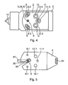
- the fluid channel ends 8,9,10,11 and 12 of the spray device 2 are in FIG. 4 and the fluid channel ends 8-1,9-1,10-1,11-1 and 12-1 of the Carrier plate 4 are shown in FIG. 5.
- 1 and 3 show on the facing away from the support member 4, the associated outer fluid channel ends 8-2, 9-2, 10-2, 11-2 and 12-2 of the fluid channels formed in the carrier element 4, which when connected to a carrier (not shown) fluidly with fluid lines are connected, which are provided in or on the carrier.
- the term “fluid” can be a liquid, in particular a coating liquid or a solvent, a gas, for example compressed air, a compressed air powder mixture as coating material or another flowable medium mean.
- the fluid line of the fluid channel end 8 for the flow of coating material in the spray device 2; the fluid channel end 9 for the Return of coating material from the spray device 2 during Spray coating breaks; the fluid channel end 10 for atomizing air Supporting the atomization of the coating material at the spray nozzle 14; the fluid channel end 11 for control compressed air for actuating one in the Spray device contained, not shown, valve, when opened the Flow coating material from the feed fluid channel end 8 to the spray nozzle 14 can and at its closed position the coating material from the flow fluid channel end 8 flow to the return fluid channel end 9 instead of to the spray nozzle 14 can, as is known for example from EP 0 846 498 A1, the Disclosure is hereby included; the fluid channel end 12 for Shaping air, which is used to shape the
- seals in the form of an annular seal (O-ring) 8-3, 9-3, 10-3, 11-3 and 12-3 arranged.
- O-ring annular seal
- These seals can be used in fluid channel shoulders of the two parts spray device 2 or support element 4 partially deepened be arranged, preferably in the spraying device 2, and are made of the same Surface level 44 slightly ahead, e.g. B. 0.1 - 0.5 mm, so that they Clamping the spray device 2 and the carrier element 4 leak-free Seal the pressure fluid.
- the seals are preferably made of resilient compressible material, such as rubber.
- the Spraying device 2 To attach the spraying device 2 to the carrier element 4, the Spraying device 2 clamped against the carrier element 4 by the clamping means 6, the seals 8-3 to 12-3 arranged between them being clamped.
- the clamping means 6 contains a clamping element 26, which is in a Axis of rotation 28 extending relative to the spraying device 2 and relative to the carrier element 4 is rotatable, which is formed by a screw 30 with which the clamping element 26 is rotatably attached to the spray device 2 on the side, which faces the carrier element 4.
- the clamping element 26 not on the spraying device 2, but on Carrier element 4 rotatably attached.
- the clamping element 26 has in Longitudinal axis of rotation at a distance from the spraying device 2 removes one transversely to the axis of rotation 28 and about the axis of rotation 28 extending first clamping surface 32, which shows the spraying device 2.
- each clamping surface 32 and 34 consists of two partial surfaces 32-1 and 32-2 and 34-1 and 34-2, which are arranged approximately diametrically to one another relative to the axis of rotation 28 are.
- the carrier element 4 there is a passage 36 in addition to the second clamping surface 34 formed by which the clamping element 26 in the longitudinal direction of the axis of rotation 28 can be moved through when the spraying device 2 is placed on the carrier element 4, so that the two clamping surfaces 32 and 34 side by side in a separating rotary position 1 come to rest, and then by turning the Clamping element 26 in its clamping engagement rotational position of Fig. 2, the first Clamping surface 32 is rotatable on the second clamping surface 34 of the carrier element 4.
- the spray device 2 is pulled against the clamping element 26, the Sealing rings 8-3 to 12-3 are clamped in between.
- the seals are made of soft, resilient material, they can manually pressed as far between the spray device 2 and the Carrier element 4 that the two clamping surfaces 32 and 34 of one height offset, non-overlapping position relative to an overlapping position are rotatable to each other.
- the clamping surfaces 32 and 34 can be flat Be surfaces that extend in a radial plane to the axis of rotation 28.
- the seals are made of harder material exist if one or both clamping surfaces 32 and 34 about the axis of rotation 28 is designed to increase thread-like in the clamping direction of rotation or are in Direction against the other clamping surface, so by manually turning the Clamping element 26 against the spray device 2 against the force of the seals the carrier element 4 is pulled.
- the tensioning element 26 preferably has a grip part 40 for manual actuation, so no tool such as a screwdriver or a A wrench is required to assemble and disassemble the sprayer 2 on the carrier element 4.
- the grip part 40 extends transversely to the axis of rotation 28 preferably over the Carrier element 4 also so that the grip part 40 outside of the carrier element 4 and in addition to the spray device 2 for clamping or releasing the Spray device 2 is actuated.
- the Passage 36 is formed as a slot which has an open end transverse to the axis of rotation 28 has through which the handle portion 40 can be inserted through the Assembly movement of the spraying device 2 and the carrier element 4.
- the angle of rotation of the clamping element 26 between the clamping engagement rotational position of Fig. 2 and the separation rotary position of Fig. 1 can be very small for example, be only 10 °.
- the angle of rotation is less than 360 °, preferably also less than 180 °. In the embodiment shown, it is only about 70 °.
- a hold-down plug device 42 is provided which is parallel to the axis of rotation 28 holds the spray device 2 on the carrier element 4.
- the sprayer 2 and that Carrier element 4 are at the hold-down plug device 42 transversely to the axis of rotation 28 can be plugged together before they are joined together by the tensioning element 26 Longitudinal direction of the axis of rotation 28 are braced.
- the hold-down connector 42 is preferably located radially outside of the axis of rotation 28 the range of seals 8-3 to 12-3.
- the hold-down plug device 42 has a formed on the spray device 2, in opposite direction than their fluid channel ends 8,9,10,11 and 12 pointing Hold-down plug surface 50 on a first pointing away from the axis of rotation 28 Heel or protrusion 48, which has a second hold-down surface 52 engages under an opposing second paragraph or Projection 54 of the carrier element 4 is formed and in the opposite direction as its fluid channel ends shows 8-1,9-1,10-1,11-1 and 12-1.
- the second paragraph or projection 54 points in the direction of the axis of rotation 28 and its second hold-down plug-in surface 52 shows in the longitudinal axis of rotation.
- the hold-down connector 42 is preferably at the rear end and that Clamping means 6 with the clamping element 26 at the front end of the spraying device 2 arranged.
- the hold-down connector 42 and the tensioning element 26 are in places positioned where they do not collide with the fluid channels.
- the axis of rotation 28 can radially inside or outside the arrangement of the fluid channel ends 8 to 12 and 8-1 be arranged to 12-1.
- An uneven load on the seals 8-2 to 12-2 can be at least partially compensated for by the hold-down plug device 42 become.
- the hold-down plug device 42 does not require any locking means for Locking the spraying device 2 with the carrier element 4.
- the hold-down plug device 42 prevents or at least limits lifting Spray device 2 from the carrier element 4, d. H. holds the sprayer 2 "down" on the carrier element 4. This simplified description applies mutatis mutandis also for embodiments in which the spray device 2 under the Carrier element 4 or is arranged next to this.
- the hold-down connector 42 is between the spray device 2 and the Carrier element 4 preferably formed on these parts themselves. It has a cross to the axis of rotation 28 directed plugging together the Spray device 2 and the carrier element 4 transverse to this axis of rotation 28, if the clamping surfaces 32, 34 are in their non-overlapping rotating separation position.
- the plug device 42 and the clamping element 26 are radial with the axis of rotation 28 a distance from each other that extends across the seals arranged.
- the hold-down connector could 42 be divided into two part-plug devices, which are transverse to Plugging direction diametrically opposite to the axis of rotation 28 are.
- the hold-down plug-in surface 50 of the spraying device 2 points in relation to the latter Fluid channel ends 8, 9, 10, 11 and 12 opposite direction.
- the mating surface 52 of the carrier element 4 shows relative to their fluid channel ends 8-1, 9-1, 10-1, 11-1, 12-1 in the opposite direction.
- the hold-down plug device 42 is preferably transverse to the axis of rotation 28 arranged outside the area of the fluid channel ends.
- the axis of rotation 28 is preferably transverse to it in the opposite direction the hold-down connector 42 outside the center of all of the Fluid channel ends 8 to 12 or 8-1 to 12-1 arranged.
- the position of the leather holding pads 50 and 52 relative to the fluid channel ends and to the seals is preferably chosen such that between the overlapping hold-down plug-in surfaces 50, 52 no or only a small one Distance of 1.0 mm or preferably 0.5 mm or less if the Spraying device 2 and the carrier element 4 and the seals 8-3, 9-3, 10-3, 11-3, 12-3 lie on top of each other between them without the tensioning element 26 to be tied together.
- the seals 8-3 to 12-3 preferably protrude only between 0.1 to 0.3 mm the surface 44 or 46 of the spray device 2 or of the carrier element 4 into which they are sunk. They are of the resilience of the Clamping element 26 is preferably only slightly compressible.
- the hold-down slots have 50, 52 a small distance of less than 1.0 mm from one another, when the sprayer 2 and the support member 4 and the seals between they lie on each other without tension by the tensioning element 26. in this connection The distance is preferably only 0.1 to 0.3 mm. This avoids that when the two parts are plugged together in the hold-down plug device 42 Part in which the seals are not embedded, with a part edge Seals damaged.
- the hold-down connector 42 helps both parts spray device 2 and carrier element 4 even with external forces hold together fluid-tight.
- the one mentioned is Distance 0.0 mm.
- abrasion by shear forces of one part, e.g. B. the support element 4, on the seals can be avoided if the Spraying device 2 and the carrier element 4 are carefully put together.
- the distance mentioned is less than 0.0 mm, so that at relaxed clamping element 26 the two parts put together Spray device 2 and carrier element 4 on the seal, which of the holding-down plug device 42 is closest, rising obliquely to each other from the Hold-down plugs are held and only then Clamping these two parts together by means of the clamping element 26 into one more parallel position to each other, in which the two parts Spray device 2 and carrier element 4 rest on all seals in a fluid-tight manner and a leak current-tight seal on the seals even at high Fluid pressure is guaranteed.
- this third variant requires that the Seals have a relatively soft compressibility. Putting the Spray device 2 with the carrier element 4 is still without one here Damage to the seals possible.
Landscapes
- Nozzles (AREA)
- Details Or Accessories Of Spraying Plant Or Apparatus (AREA)
Abstract
Description
- Fig. 1
- eine Unteransicht der Spritzbeschichtungseinrichtung nach der Erfindung, wobei eine Spritzvorrichtung und ein Trägerelement aufeinandergelegt, aber noch nicht miteinander verspannt snd, und ein Spannelemt in einer Trenn-Drehstellung ist,
- Fig. 2
- eine Unteransicht der Spritzbeschichtungseinrichtung nach der Erfindung, wobei die Spritzvorrichtung an dem Trägerelement festgespannt ist, indem das Spannelement relativ zur Spritzvorrichtung und relativ zu dem Trägerelement in eine Spanneingriffs-Drehstellung manuell gedreht wurde,
- Fig. 3
- eine Seitenansicht der Spritzbeschichtungseinrichtung nach der Erfindung, wobei die Spritzvorrichtung auf das Trägerelement teilweise gespannt wurde, jedoch ein Spannelement noch nicht seine endgültige Spanneingriffs-Drehstellung von Fig. 2 erreicht hat,
- Fig. 4
- eine Unteransicht der Spritzvorrichtung längs der Ebene IV-IV von Fig. 3 ohne das Trägerelement,
- Fig. 5
- eine Draufsicht auf das Trägerelement längs der Ebene V-V von Fig. 3.
Claims (13)
- Spritzbeschichtungseinrichtung enthaltend eine Spritzvorrichtung (2), ein Trägerelement (4), an welchem die Spritzvorrichtung (2) durch Spannmittel (6) lösbar befestigbar ist, Fluidkanalenden (8-1,9-1,10-1,11-1,12-1) von Fluidkanälen im Trägerelement (4), welche Fluidkanalenden (8,9,10,11,12) von Fluidkanälen in der Spritzvorrichtung (2) gegenüber liegen zur Fluidübertragung dazwischen, wenn die Spritzvorrichtung (2) am Trägerelement (4) befestigt ist, Dichtungen(8-3,9-3,10-3,11-3,12-3) an den Fluidkanalenden zur Abdichtung zwischen dem Trägerelement (4) und der Spritzvorrichtung (2), wobei mittels der Spannmittel (6) die Spritzvorrichtung (2) gegen das Trägerelement (4) spannbar und dabei dazwischen die Dichtungen (8-3,9-3,10-3,11-3,12-3) einspannbar sind,
dadurch gekennzeichnet, daß die Spannmittel (6) ein Spannelement (26) enthalten, welches an einem der beiden Teile Spritzvorrichtung (2) oder Trägerelement (4) relativ zur Spritzvorrichtung (2) und relativ zum Trägerelement (4) drehbar befestigt ist und eine erste Spannfläche (32) aufweist, daß eine zweite Spannfläche (34) an dem betreffenden anderen der beiden Teile Spritzvorrichtung (2) oder Trägerelement (4) vorgesehen ist, daß sich die Drehachse (28) des Spannelements (26) in Spannrichtung erstreckt, in welcher die Spritzvorrichtung (2) und das Trägerelement (4) zusammenspannbar sind, und daß durch Drehen des Spannelements (26) relativ zu beiden Teilen (2,4) die erste Spannfläche in Spanneingriff mit der zweiten Spannfläche drehbar ist, um die Spritzvorrichtung (2) gegen das Trägerelement (4) zu spannen und dabei dazwischen die Dichtungen (8-3,9-3,10-3,11-3,12-3) einzuspannen. - Spritzbeschichtungseinrichtung nach Anspruch 1,
dadurch gekennzeichnet, daß mindestens eine der beiden Spannflächen (32,34) sich über einen Winkelbereich von weniger als 360° um die Drehachse (28) erstreckt und die betreffende andere Spannfläche sich um weniger als den verbleibenden Winkelbereich um die Drehachse (28) erstreckt, daß das Spannelement (26) relativ zur Spritzvorrichtung (2) und relativ zum Trägerelement (4) zwischen einer Trenn-Drehstellung, bei welcher die beiden Spannflächen (32,34) einander nicht überlappend in nebeneinander liegenden Winkelbereichen liegen, und der Spanneingriffs-Drehstellung drehbar ist, bei welcher die beiden Spannflächen (32,34) mindestens teilweise einander überlappen und gegeneinander spannbar sind, daß derjenige Teil Spritzvorrichtung (2) oder Trägerelement (4), an welchem das Spannelement (26) nicht befestigt ist, mit einem Durchgang (36) versehen ist, durch welchen das am einen Teil befestigte Spannelement (26) hindurchsteckbar ist durch die Zusammensetzbewegung der beiden Teile und deren Fluidkanalenden (8,8-1;9,9-1;10-10-1;11,11-1;12,12-1) relativ zueinander, wobei sich das Spannelement (26) in der Trenn-Drehstellung befindet und die Spannflächen (32,34) in Drehachsenlängsrichtung in eine Position bringbar sind, in welcher sie durch Drehen des Spannelements (26) in Spanneingriff bringbar sind. - Spritzbeschichtungseinrichtung nach einem der vorhergehenden Ansprüche,
dadurch gekennzeichnet, daß mindestens eine der beiden Spannflächen (32,34) in einem Teilbereich um die Drehachse (28) herum gewindeartig in Richtung gegen die andere Spannfläche (32,34) ansteigend ausgebildet ist. - Spritzbeschichtungseinrichtung nach einem der vorhergehenden Ansprüche,
dadurch gekennzeichnet, daß das Spannelement (26) einen Griffteil (40) zur manuellen Betätigung aufweist. - Spritzbeschichtungseinrichtung nach Anspruch 4,
dadurch gekennzeichnet, daß der Griffteil (40) ein sich quer von der Drehachse (28) weg erstreckender Hebel ist, dessen von der Drehachse (28) entferntes Ende über den mit der zweiten Spannfläche (34) versehenen anderen der beiden Teile Spritzvorrichtung (2) oder Trägerelement (4) hinausragt und außerhalb davon manuell greifbar ist. - Spritzbeschichtungseinrichtung nach einem der vorhergehenden Ansprüche,
dadurch gekennzeichnet, daß der relative Verdrehwinkel der beiden Spannflächen (32,34) zwischen ihre Spanneingriffs-Drehstellung und ihrer einander nicht überlappenden Trenn-Drehstellung gleich oder kleiner 180° ist. - Spritzbeschichtungseinrichtung nach einem der vorhergehenden Ansprüche,
dadurch gekennzeichnet, daß zwischen der Spritzvorrichtung (2) und dem Trägerelement (4) eine Niederhalte-Steckvorrichtung (42) gebildet ist, die eine quer zur Drehachse (28) gerichtete Steckrichtung aufweist zum Zusammenstecken der Spritzvorrichtung (2) und des Trägerelements (4) quer zur Drehachse (28), wenn die Spannflächen (32,34) in ihrer einander nicht überlappenden Trenn-Drehstellung sind. - Spritzbeschichtungseinrichtung nach Anspruch 7,
dadurch gekennzeichnet, daß die Niederhalte-Steckvorrichtung (42) und das Spannelement (26) radial zur Drehachse (28) mit einem sich über wenigstens eine der Dichtungen erstreckenden Abstand voneinander entfernt angeordnet sind. - Spritzbeschichtungseinrichtung nach Anspruch 7 oder 8,
dadurch gekennzeichnet, daß die Niederhalte-Steckvorrichtung (42) eine an der Spritzvorrichtung (2) gebildete Niederhalte-Steckfläche (50) und eine an dem Trägerelement (4) gebildete Niederhalte-Steckfläche (52) aufweist, die mit Abstand von der Drehachse (28) einander in Drehachsenlängsrichtung gegenüber liegend gebildet sind, daß die Niederhalte-Steckfläche (50) der Spritzvorrichtung (2) in entgegengesetzter Richtung als deren Fluidkanalenden (8,9,10,11,12) zeigt, daß die Niederhalte-Steckfläche (52) des Trägerelements (4) in entgegengesetzter Richtung als dessen Fluidkanalenden (8-1,9-1,10-1,11-1,12-1) zeigt. - Spritzbeschichtungseinrichtung nach einem der Ansprüche 7 bis 9,
dadurch gekennzeichnet, daß die Niederhalte-Steckvorrichtung (42) mit radialem, sich über die Dichtungen erstreckendem Abstand von der Drehachse (28) außerhalb der Anordnung der Fluidkanalenden angeordnet ist. - Spritzbeschichtungseinrichtung nach einem der Ansprüche 7 bis 10,
dadurch gekennzeichnet, daß die Drehachse (28) quer zu ihr in entgegengesetzter Richtung wie die Niederhalte-Steckvorrichtung (42) außerhalb der Mitte der Gesamtheit der Fluidkanalenden (8 bis 12, 8-1 bis 12-1) angeordnet ist. - Spritzbeschichtungseinrichtung nach einem der Ansprüche 9 bis 11,
dadurch gekennzeichnet, daß zwischen den einander überlappend angeordneten Niederhalte-Steckflächen (50,52) kein oder nur ein kleiner Abstand von 1,0 mm, vorzugsweise von 0,5 mm oder weniger ist, wenn die Spritzvorrichtung (2) und das Trägerelement (4) und die Dichtungen (8-3,9-3,10-3,11-3,12-3) zwischen ihnen aufeinander liegen, ohne von dem Spannelement (26) eingespannt zu sein. - Spritzbeschichtungseinrichtung nach einem der Ansprüche 9 bis 12,
dadurch gekennzeichnet, daß mindestens eine der Niederhalte-Steckflächen (50,52) an einem Absatz oder Vorsprung (48) gebildet ist, der sich in Richtung des Abstandes zwischen der Drehachse (28) des Spannelements (26) und der Niederhalte-Steckvorrichtung (42) erstreckt.
Applications Claiming Priority (2)
| Application Number | Priority Date | Filing Date | Title |
|---|---|---|---|
| DE10142074A DE10142074A1 (de) | 2001-08-29 | 2001-08-29 | Spritzbeschichtungseinrichtung |
| DE10142074 | 2001-08-29 |
Publications (3)
| Publication Number | Publication Date |
|---|---|
| EP1287901A2 true EP1287901A2 (de) | 2003-03-05 |
| EP1287901A3 EP1287901A3 (de) | 2005-06-15 |
| EP1287901B1 EP1287901B1 (de) | 2006-07-19 |
Family
ID=7696833
Family Applications (1)
| Application Number | Title | Priority Date | Filing Date |
|---|---|---|---|
| EP02011814A Expired - Lifetime EP1287901B1 (de) | 2001-08-29 | 2002-05-28 | Sprühbeschichtungseinrichtung |
Country Status (5)
| Country | Link |
|---|---|
| US (1) | US6802463B2 (de) |
| EP (1) | EP1287901B1 (de) |
| JP (1) | JP2003062498A (de) |
| DE (2) | DE10142074A1 (de) |
| ES (1) | ES2271145T3 (de) |
Cited By (3)
| Publication number | Priority date | Publication date | Assignee | Title |
|---|---|---|---|---|
| WO2007122132A1 (de) | 2006-04-21 | 2007-11-01 | Krautzberger Gmbh | Schnellwechseladapter und spritzapparat zur montage auf einem schnellwechseladapter |
| DE102007014216A1 (de) * | 2007-03-24 | 2008-09-25 | ITW Oberflächentechnik GmbH & Co. KG | Spritzpistolen-Leistungsverbindungsvorrichtung |
| EP3100789A1 (de) * | 2015-06-05 | 2016-12-07 | J. Wagner AG | Automatik-spritzpistole zum versprühen eines fluids |
Families Citing this family (7)
| Publication number | Priority date | Publication date | Assignee | Title |
|---|---|---|---|---|
| FR2872717B1 (fr) * | 2004-07-12 | 2006-09-15 | Itw Surfaces & Finitions Sa | Pistolet de pulverisation automatique comprenant un corps de pulverisation monte sur une embase d'alimentation |
| DE102007017387B4 (de) * | 2006-04-21 | 2009-04-23 | Krautzberger Gmbh | Spritzvorrichtung |
| US20080011333A1 (en) * | 2006-07-13 | 2008-01-17 | Rodgers Michael C | Cleaning coating dispensers |
| DE102014102548A1 (de) | 2013-11-28 | 2015-05-28 | Düsen-Schlick GmbH | Vorrichtung zum Einsatz in einem Tabletten-Coater |
| US10226917B2 (en) * | 2015-07-27 | 2019-03-12 | Dmg Mori Seiki Usa | Powder delivery systems and methods for additive manufacturing apparatus |
| CN106622780A (zh) * | 2016-12-26 | 2017-05-10 | 天津绿林森网络技术有限公司 | 一种可调节汽车方向盘喷涂夹具装置 |
| CN115179540B (zh) * | 2022-07-08 | 2023-07-21 | 凯麒斯食品工业(江苏)有限公司 | 一种塑料制品用覆膜装置 |
Citations (1)
| Publication number | Priority date | Publication date | Assignee | Title |
|---|---|---|---|---|
| EP0846498A1 (de) | 1996-12-06 | 1998-06-10 | ITW Oberflächentechnik GmbH | Sprühbeschichtungseinrichtung mit automatischer Funktionsüberwachung |
Family Cites Families (11)
| Publication number | Priority date | Publication date | Assignee | Title |
|---|---|---|---|---|
| US2859728A (en) * | 1956-08-29 | 1958-11-11 | James D Hobdy | Spray nozzle |
| US3653599A (en) * | 1970-05-19 | 1972-04-04 | Speco Inc | Fluid spray apparatus |
| US4230023A (en) * | 1977-12-05 | 1980-10-28 | Scovill Manufacturing Company | Clamping apparatus |
| DE3309555A1 (de) * | 1983-03-17 | 1984-09-20 | Grüner, Horst, Dipl.-Ing. (FH), 7347 Bad Überkingen | In verbindung mit einer werkstueck-bearbeitungsmaschine zu verwendende einrichtung zum spannen bzw. abspannen von werkstuecken |
| US4602742A (en) * | 1984-10-09 | 1986-07-29 | Penson Joe R | Mobile spraying unit with selectable spray position |
| DE4022643C1 (en) * | 1990-07-17 | 1991-11-21 | Heidelberger Druckmaschinen Ag, 6900 Heidelberg, De | Electrostatic powder spray gun - has sleeve which can be screwed over contact spindle from one end |
| US5265800A (en) * | 1993-01-25 | 1993-11-30 | Nordson Corporation | Adhesive spray gun with adjustable module and method of assembling |
| DE4416311A1 (de) * | 1994-05-09 | 1995-11-16 | Itw Oberflaechentechnik Gmbh | Sprühgerät-Befestigungsvorrichtung |
| US5934520A (en) * | 1997-11-03 | 1999-08-10 | Nordson Corporation | Liquid dispensing device |
| US6478242B1 (en) * | 1999-09-16 | 2002-11-12 | Nordson Corporation | Powder spray gun |
| IT1314336B1 (it) * | 1999-12-29 | 2002-12-09 | Omba S R L | Paletta per il bloccaggio di un pezzo da sottoporre a lavorazioni |
-
2001
- 2001-08-29 DE DE10142074A patent/DE10142074A1/de not_active Withdrawn
-
2002
- 2002-05-28 DE DE50207542T patent/DE50207542D1/de not_active Expired - Lifetime
- 2002-05-28 ES ES02011814T patent/ES2271145T3/es not_active Expired - Lifetime
- 2002-05-28 EP EP02011814A patent/EP1287901B1/de not_active Expired - Lifetime
- 2002-07-12 JP JP2002204176A patent/JP2003062498A/ja active Pending
- 2002-08-26 US US10/227,457 patent/US6802463B2/en not_active Expired - Fee Related
Patent Citations (1)
| Publication number | Priority date | Publication date | Assignee | Title |
|---|---|---|---|---|
| EP0846498A1 (de) | 1996-12-06 | 1998-06-10 | ITW Oberflächentechnik GmbH | Sprühbeschichtungseinrichtung mit automatischer Funktionsüberwachung |
Cited By (5)
| Publication number | Priority date | Publication date | Assignee | Title |
|---|---|---|---|---|
| WO2007122132A1 (de) | 2006-04-21 | 2007-11-01 | Krautzberger Gmbh | Schnellwechseladapter und spritzapparat zur montage auf einem schnellwechseladapter |
| DE102007014216A1 (de) * | 2007-03-24 | 2008-09-25 | ITW Oberflächentechnik GmbH & Co. KG | Spritzpistolen-Leistungsverbindungsvorrichtung |
| WO2008116778A1 (de) * | 2007-03-24 | 2008-10-02 | ITW Oberflächentechnik GmbH & Co. KG | Spritzpistolen-leitungsverbindungsvorrichtung |
| US8256694B2 (en) | 2007-03-24 | 2012-09-04 | Ulrich Griesenbruch | Spray-gun line-connecting device |
| EP3100789A1 (de) * | 2015-06-05 | 2016-12-07 | J. Wagner AG | Automatik-spritzpistole zum versprühen eines fluids |
Also Published As
| Publication number | Publication date |
|---|---|
| EP1287901A3 (de) | 2005-06-15 |
| EP1287901B1 (de) | 2006-07-19 |
| US20030042339A1 (en) | 2003-03-06 |
| DE10142074A1 (de) | 2003-04-10 |
| ES2271145T3 (es) | 2007-04-16 |
| DE50207542D1 (de) | 2006-08-31 |
| US6802463B2 (en) | 2004-10-12 |
| JP2003062498A (ja) | 2003-03-04 |
Similar Documents
| Publication | Publication Date | Title |
|---|---|---|
| DE2900141A1 (de) | Drehbare spritzduese | |
| DE3237213A1 (de) | Duese mit schnelltrennkupplung | |
| DE2622396A1 (de) | Spritzduese | |
| DE202014011108U1 (de) | Dichtstrompumpe und Komponenten | |
| EP0290869B1 (de) | Vorrichtung zum auswechselbaren Anschliessen | |
| DE2313983A1 (de) | In eine fluidleitung einschaltbare kupplungseinrichtung zur aufnahme mindestens einer beeinflussungsvorrichtung fuer das fluid | |
| EP1287901B1 (de) | Sprühbeschichtungseinrichtung | |
| DE102015121762A1 (de) | Düsenanordnung für fließfähige Substanzen | |
| DE102008047266A1 (de) | Vorrichtung zum Auftragen von Fluiden | |
| EP3043954B1 (de) | Spannvorrichtung zum einspannen mindestens eines spannnippels | |
| DE112015001056B4 (de) | Vakuumpumpe | |
| WO2021119698A1 (de) | Unterdruck-greiferelement und unterdruck-greifervorrichtung | |
| DE10142228A1 (de) | Fluidspritzvorrichtung | |
| DE19914040B4 (de) | Sprühpistolen-Roboter-Adapter | |
| DE4416311A1 (de) | Sprühgerät-Befestigungsvorrichtung | |
| DE202024104428U1 (de) | Ventilkern-Demontagewerkzeug für Reifenventile | |
| DE102004047924A1 (de) | Spritzapparat und Wechsel- und Befestigungsvorrichtung für Spritzapparate | |
| EP1981649B1 (de) | Schnellwechseladapter und spritzapparat zur montage auf einem schnellwechseladapter | |
| EP0716261A2 (de) | Verbindungseinrichtung zum Anschliessen von Spritzdüsen an eine Druckleitung | |
| DE4039241A1 (de) | Drehschieber fuer vakuumleitungen | |
| DE202013101137U1 (de) | Vorrichtung zum Begrenzen des Nadelhubs bei einem Spritzgerät, insbesondere einer Spritzpistole und Spritzgerät, insbesondere Spritzpistole mit einer solchen Vorrichtung | |
| DE202006008212U1 (de) | Handbetätigtes Druckregelventil für Druckluftpistolen | |
| EP1362672A2 (de) | Vorrichtung zum Halten und Eindrehen von Schrauben | |
| DE4104009C2 (de) | Kupplungsstück . | |
| DE3919546C2 (de) |
Legal Events
| Date | Code | Title | Description |
|---|---|---|---|
| PUAI | Public reference made under article 153(3) epc to a published international application that has entered the european phase |
Free format text: ORIGINAL CODE: 0009012 |
|
| AK | Designated contracting states |
Kind code of ref document: A2 Designated state(s): AT BE CH CY DE DK ES FI FR GB GR IE IT LI LU MC NL PT SE TR |
|
| AX | Request for extension of the european patent |
Extension state: AL LT LV MK RO SI |
|
| PUAL | Search report despatched |
Free format text: ORIGINAL CODE: 0009013 |
|
| AK | Designated contracting states |
Kind code of ref document: A3 Designated state(s): AT BE CH CY DE DK ES FI FR GB GR IE IT LI LU MC NL PT SE TR |
|
| AX | Request for extension of the european patent |
Extension state: AL LT LV MK RO SI |
|
| RIC1 | Information provided on ipc code assigned before grant |
Ipc: 7B 05B 15/06 B Ipc: 7B 05B 13/02 A |
|
| 17P | Request for examination filed |
Effective date: 20051022 |
|
| GRAP | Despatch of communication of intention to grant a patent |
Free format text: ORIGINAL CODE: EPIDOSNIGR1 |
|
| AKX | Designation fees paid |
Designated state(s): DE ES FR GB IT |
|
| GRAS | Grant fee paid |
Free format text: ORIGINAL CODE: EPIDOSNIGR3 |
|
| GRAA | (expected) grant |
Free format text: ORIGINAL CODE: 0009210 |
|
| AK | Designated contracting states |
Kind code of ref document: B1 Designated state(s): DE ES FR GB IT |
|
| PG25 | Lapsed in a contracting state [announced via postgrant information from national office to epo] |
Ref country code: IT Free format text: LAPSE BECAUSE OF FAILURE TO SUBMIT A TRANSLATION OF THE DESCRIPTION OR TO PAY THE FEE WITHIN THE PRESCRIBED TIME-LIMIT;WARNING: LAPSES OF ITALIAN PATENTS WITH EFFECTIVE DATE BEFORE 2007 MAY HAVE OCCURRED AT ANY TIME BEFORE 2007. THE CORRECT EFFECTIVE DATE MAY BE DIFFERENT FROM THE ONE RECORDED. Effective date: 20060719 |
|
| REG | Reference to a national code |
Ref country code: GB Ref legal event code: FG4D Free format text: NOT ENGLISH |
|
| REF | Corresponds to: |
Ref document number: 50207542 Country of ref document: DE Date of ref document: 20060831 Kind code of ref document: P |
|
| GBT | Gb: translation of ep patent filed (gb section 77(6)(a)/1977) |
Effective date: 20061024 |
|
| ET | Fr: translation filed | ||
| REG | Reference to a national code |
Ref country code: ES Ref legal event code: FG2A Ref document number: 2271145 Country of ref document: ES Kind code of ref document: T3 |
|
| PLBE | No opposition filed within time limit |
Free format text: ORIGINAL CODE: 0009261 |
|
| STAA | Information on the status of an ep patent application or granted ep patent |
Free format text: STATUS: NO OPPOSITION FILED WITHIN TIME LIMIT |
|
| 26N | No opposition filed |
Effective date: 20070420 |
|
| PGFP | Annual fee paid to national office [announced via postgrant information from national office to epo] |
Ref country code: DE Payment date: 20120529 Year of fee payment: 11 |
|
| PGFP | Annual fee paid to national office [announced via postgrant information from national office to epo] |
Ref country code: GB Payment date: 20120525 Year of fee payment: 11 Ref country code: FR Payment date: 20120607 Year of fee payment: 11 |
|
| PGFP | Annual fee paid to national office [announced via postgrant information from national office to epo] |
Ref country code: IT Payment date: 20120524 Year of fee payment: 11 |
|
| PGFP | Annual fee paid to national office [announced via postgrant information from national office to epo] |
Ref country code: ES Payment date: 20120528 Year of fee payment: 11 |
|
| GBPC | Gb: european patent ceased through non-payment of renewal fee |
Effective date: 20130528 |
|
| PG25 | Lapsed in a contracting state [announced via postgrant information from national office to epo] |
Ref country code: DE Free format text: LAPSE BECAUSE OF NON-PAYMENT OF DUE FEES Effective date: 20131203 |
|
| PG25 | Lapsed in a contracting state [announced via postgrant information from national office to epo] |
Ref country code: IT Free format text: LAPSE BECAUSE OF NON-PAYMENT OF DUE FEES Effective date: 20130528 |
|
| REG | Reference to a national code |
Ref country code: DE Ref legal event code: R119 Ref document number: 50207542 Country of ref document: DE Effective date: 20131203 |
|
| REG | Reference to a national code |
Ref country code: FR Ref legal event code: ST Effective date: 20140131 |
|
| PG25 | Lapsed in a contracting state [announced via postgrant information from national office to epo] |
Ref country code: GB Free format text: LAPSE BECAUSE OF NON-PAYMENT OF DUE FEES Effective date: 20130528 |
|
| PG25 | Lapsed in a contracting state [announced via postgrant information from national office to epo] |
Ref country code: FR Free format text: LAPSE BECAUSE OF NON-PAYMENT OF DUE FEES Effective date: 20130531 |
|
| REG | Reference to a national code |
Ref country code: ES Ref legal event code: FD2A Effective date: 20140611 |
|
| PG25 | Lapsed in a contracting state [announced via postgrant information from national office to epo] |
Ref country code: ES Free format text: LAPSE BECAUSE OF NON-PAYMENT OF DUE FEES Effective date: 20130529 |