EP1287910B1 - Tamis pour usage dans un dispositif de filtration vibrant - Google Patents
Tamis pour usage dans un dispositif de filtration vibrant Download PDFInfo
- Publication number
- EP1287910B1 EP1287910B1 EP02254478A EP02254478A EP1287910B1 EP 1287910 B1 EP1287910 B1 EP 1287910B1 EP 02254478 A EP02254478 A EP 02254478A EP 02254478 A EP02254478 A EP 02254478A EP 1287910 B1 EP1287910 B1 EP 1287910B1
- Authority
- EP
- European Patent Office
- Prior art keywords
- screen
- screens
- engagement
- support structure
- profile
- Prior art date
- Legal status (The legal status is an assumption and is not a legal conclusion. Google has not performed a legal analysis and makes no representation as to the accuracy of the status listed.)
- Expired - Lifetime
Links
Images


Classifications
-
- B—PERFORMING OPERATIONS; TRANSPORTING
- B07—SEPARATING SOLIDS FROM SOLIDS; SORTING
- B07B—SEPARATING SOLIDS FROM SOLIDS BY SIEVING, SCREENING, SIFTING OR BY USING GAS CURRENTS; SEPARATING BY OTHER DRY METHODS APPLICABLE TO BULK MATERIAL, e.g. LOOSE ARTICLES FIT TO BE HANDLED LIKE BULK MATERIAL
- B07B1/00—Sieving, screening, sifting, or sorting solid materials using networks, gratings, grids, or the like
- B07B1/46—Constructional details of screens in general; Cleaning or heating of screens
- B07B1/4609—Constructional details of screens in general; Cleaning or heating of screens constructional details of screening surfaces or meshes
- B07B1/4645—Screening surfaces built up of modular elements
-
- B—PERFORMING OPERATIONS; TRANSPORTING
- B01—PHYSICAL OR CHEMICAL PROCESSES OR APPARATUS IN GENERAL
- B01D—SEPARATION
- B01D29/00—Filters with filtering elements stationary during filtration, e.g. pressure or suction filters, not covered by groups B01D24/00 - B01D27/00; Filtering elements therefor
- B01D29/01—Filters with filtering elements stationary during filtration, e.g. pressure or suction filters, not covered by groups B01D24/00 - B01D27/00; Filtering elements therefor with flat filtering elements
- B01D29/05—Filters with filtering elements stationary during filtration, e.g. pressure or suction filters, not covered by groups B01D24/00 - B01D27/00; Filtering elements therefor with flat filtering elements supported
-
- B—PERFORMING OPERATIONS; TRANSPORTING
- B01—PHYSICAL OR CHEMICAL PROCESSES OR APPARATUS IN GENERAL
- B01D—SEPARATION
- B01D29/00—Filters with filtering elements stationary during filtration, e.g. pressure or suction filters, not covered by groups B01D24/00 - B01D27/00; Filtering elements therefor
- B01D29/44—Edge filtering elements, i.e. using contiguous impervious surfaces
- B01D29/445—Bar screens
-
- B—PERFORMING OPERATIONS; TRANSPORTING
- B01—PHYSICAL OR CHEMICAL PROCESSES OR APPARATUS IN GENERAL
- B01D—SEPARATION
- B01D29/00—Filters with filtering elements stationary during filtration, e.g. pressure or suction filters, not covered by groups B01D24/00 - B01D27/00; Filtering elements therefor
- B01D29/50—Filters with filtering elements stationary during filtration, e.g. pressure or suction filters, not covered by groups B01D24/00 - B01D27/00; Filtering elements therefor with multiple filtering elements, characterised by their mutual disposition
- B01D29/52—Filters with filtering elements stationary during filtration, e.g. pressure or suction filters, not covered by groups B01D24/00 - B01D27/00; Filtering elements therefor with multiple filtering elements, characterised by their mutual disposition in parallel connection
-
- B—PERFORMING OPERATIONS; TRANSPORTING
- B01—PHYSICAL OR CHEMICAL PROCESSES OR APPARATUS IN GENERAL
- B01D—SEPARATION
- B01D33/00—Filters with filtering elements which move during the filtering operation
- B01D33/01—Filters with filtering elements which move during the filtering operation with translationally moving filtering elements, e.g. pistons
- B01D33/03—Filters with filtering elements which move during the filtering operation with translationally moving filtering elements, e.g. pistons with vibrating filter elements
- B01D33/0346—Filters with filtering elements which move during the filtering operation with translationally moving filtering elements, e.g. pistons with vibrating filter elements with flat filtering elements
- B01D33/0376—Filters with filtering elements which move during the filtering operation with translationally moving filtering elements, e.g. pistons with vibrating filter elements with flat filtering elements supported
-
- B—PERFORMING OPERATIONS; TRANSPORTING
- B01—PHYSICAL OR CHEMICAL PROCESSES OR APPARATUS IN GENERAL
- B01D—SEPARATION
- B01D33/00—Filters with filtering elements which move during the filtering operation
- B01D33/35—Filters with filtering elements which move during the filtering operation with multiple filtering elements characterised by their mutual disposition
- B01D33/37—Filters with filtering elements which move during the filtering operation with multiple filtering elements characterised by their mutual disposition in parallel connection
-
- B—PERFORMING OPERATIONS; TRANSPORTING
- B01—PHYSICAL OR CHEMICAL PROCESSES OR APPARATUS IN GENERAL
- B01D—SEPARATION
- B01D2201/00—Details relating to filtering apparatus
- B01D2201/40—Special measures for connecting different parts of the filter
-
- B—PERFORMING OPERATIONS; TRANSPORTING
- B07—SEPARATING SOLIDS FROM SOLIDS; SORTING
- B07B—SEPARATING SOLIDS FROM SOLIDS BY SIEVING, SCREENING, SIFTING OR BY USING GAS CURRENTS; SEPARATING BY OTHER DRY METHODS APPLICABLE TO BULK MATERIAL, e.g. LOOSE ARTICLES FIT TO BE HANDLED LIKE BULK MATERIAL
- B07B2201/00—Details applicable to machines for screening using sieves or gratings
- B07B2201/02—Fastening means for fastening screens to their frames which do not stretch or sag the screening surfaces
Definitions
- This invention concerns screens of the type disclosed in UK Patent Specification GB 2,322,590 and GB 2,292,533 and to a method and device for joining such screens end to end.
- Screens of the type described such as shown in GB 2,322,590 and GB 2,292,533 have been provided with male and female edge formations at the ends of the screen frames, for the purpose of sealing the joint and to accommodate angular orientation of one screen relative to another when fitted within a shaker or sifting machine.
- none of the joints reliably connect one screen to the other to enable the two screens to be handled as one, when joined together and located in a frame support structure of such a machine.
- a screen for use as a filter in a vibratory filtration equipment as characterised in claim 1.
- the invention also lies in a screen as aforesaid when fitted to an adjoining similar screen wherein the engagement of one profile by another also serves to close the gap between the two screen frames and prevent at least particulate material from passing therebetween.
- the engagement of the two profiles is adapted to prevent liquid from passing therebetween.
- the combination of a screen as aforesaid, together with a second similar screen are arranged in tandem, one behind the other, the inner one constituting the rear screen and the other the front screen of a pair when viewed from the front of the machine.
- the two screens may be in generally planar alignment.
- the support structure may be adapted so as to cause one screen to be angled relative to the plane of the other.
- the engagement of the channel profiles provides a reliable force-transmitting connection to enable a rear screen to be removed from the support structure simply by pulling out the front screen of the pair.
- a support structure for such a pair of screens typically comprises parallel rails for supporting left and right hand edges of the two screen frames, a transversely extending rear ledge for supporting the far end of the rear screen frame, and an inflatable rim seal which when inflated and pressurised firmly sandwiches the edges of the frames between the inflated seal and the rails and the ledge so as to prevent any movement of the frames in the support structure once the seal is inflated, but which when deflated permits movement of the screens relative to the rails for movement in and out of the support structure and also vertical movement of one frame relative to the other, to facilitate the entry of one profile into the other to effect the said engagement with the two screens in the support structure and the invention lies in a support structure as aforesaid when fitted with two such screens.
- a method of joining two screens as aforesaid in a support structure which comprises parallel rails for supporting left and right hand edges of the two screens and a transversely extending rear ledge for supporting the far end of the rear screen, and an inflatable rim seal which when inflated and pressurised firmly sandwiches the edges of the screens between the inflated seal and the rails and the ledge so as to prevent any movement of the screens in the support structure once the seal in inflated, but which when deflated permits movement of the screens relative to the rails for movement in and out of the support structure and also vertical movement of one screen relative to the other, comprising the steps of lifting up the end of the screen provided with the downwardly open profile within the support structure relative to the upwardly open profile provided at the end of the other screen, and allowing the downwardly open profile to pass up and over the inclined face of the upwardly open profile and thereafter to drop into and engage the channel thereof to effect the engagement.
- the two screens may be slid one after the other into the support structure with the first to be slid into position being arranged with its upwardly open profile at its trailing end.
- the second screen to be pushed into the support structure is inserted until its leading end profile abuts the rear end of the first screen, the external shape of the profiles being adapted to cause the leading end profile of the second screen to rise up and over the inclined face on the rear end of the first screen with continued forward movement of the second screen.
- the screens may be located in a support structure comprising parallel rails for supporting the left and right hand edges of the screens and a transversely extending rear ledge for supporting the far end of the rear screen, and an inflatable rim seal is provided which when pressurised firmly sandwiches the edges of the screens between the inflated seal and the rails and the ledge. Once inflated, the squeeze exerted on the frame edges prevents any movement of the screens.
- both screens are not only capable of being slid along the rails but are also capable of limited relative vertical movement. It is this latter degree of freedom which renders the engagement shown in the earlier Patent Specifications insufficient to provide a reliable traction connection to be provided between the two screens.
- this relative vertical movement which is possible when the seal is deflated, may be employed as already described to assist in joining the edges of a pair of screen frames embodying the invention, to permit one frame to be lifted relative to the other to allow its outboard downwardly extending edge profile lip to be lifted over the corresponding but upwardly extending edge profile lip at the adjoining end of the other frame, thereafter to be dropped thereinto to effect the join.
- the two screens are positively joined together and sliding movement of one, in a direction perpendicular to the join, will be reliably transmitted to the other, so that the two will move as one.
- the rear frame therefore can be pulled out simply by pulling the front frame. Once the latter is clear of the support assembly within the chamber, the edge profile of its rear end can be disengaged from the edge profile along the front edge of the rear screen. The latter is then available to be pulled out by gripping it along its front leading edge, and pulling.
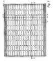
- a screen similar to that described in relation to the drawings in UK Patent 2,322,590 is shown in plan view from above.
- the screen is comprises of a GRP frame 10 having an orthogonal array of ribs which divide the area bounded by the outer edges of the frame, into a plurality of rectangular similarly sizes windows such as 12.
- woven wire cloth is stretched over the frame and bonded to the outer edges and the ribs in a manner such as described in UK Patent 2,322,590 .
- the frames will normally be arranged in tandem in a support assembly with the left hand end of the frame of Fig 1 abutting what would be the right hand end of a similar frame, ahead of it (i.e. to the left of the screen in Fig 1), in a support assembly.
- the latter includes two rails (not shown) which engage the undersides of the two longer edges 14, 16 (see Fig 2) of the frame, and a lip (also not shown) co-planar with the rails, which extends across the support assembly to support the underside 18 of the edge profile 20 along the rear edge of the innermost frame.
- a second pair of screens is arranged co-planar with, and to one side of, the first pair, supported in a similar manner on two parallel rails and a transverse rear lip. Filtering is achieved by pouring mud onto the area defined by all four screens, and shaking the support assembly while so doing, causing solids to migrate over the screens and liquid to pass through the woven wire cloth.
- the junction between the two screens is formed by engaging the downwardly protruding lip 22 of the edge of one frame into the upwardly facing channel 24 of the edge profile along the adjoining edge of the other frame.
- the underside 26 of the lip 22 is inclined at approximately 45° and the upper edge 28 of the lip 30 defining the channel 24 is similarly inclined at 45°, in a complementary fashion to the slope 26 on 22.
- sliding movement of the frame carrying lip 22 in a direction towards the edge of an aligned frame carrying the channel 24 will, when face 26 engages face 28, cause the frame carrying lip 22 to rise up due to the engagement of the two 45° inclined surfaces, until the lip 22 can drop into the channel 24, whereupon the two frames are securely joined edge to edge.
- the lip 22 By ensuring that the lip 22 extends fully across the width of the frame (as seen at the right hand end of Fig 1) even if the co-operating female profile of lip 30 and channel 24 does not extend fully across the end of the other frame, (as shown at the left hand end of Fig 1), the lip 22 will act as a cover for the join, and this, and its engagement in the channel 24, will prevent any particulate material from passing through the join between the two edges.
Landscapes
- Chemical & Material Sciences (AREA)
- Chemical Kinetics & Catalysis (AREA)
- Combined Means For Separation Of Solids (AREA)
- Lighting Device Outwards From Vehicle And Optical Signal (AREA)
- Filtration Of Liquid (AREA)
- Circuit For Audible Band Transducer (AREA)
- Control Of Motors That Do Not Use Commutators (AREA)
- Filters And Equalizers (AREA)
- Vibration Prevention Devices (AREA)
- Laser Beam Processing (AREA)
- Piezo-Electric Or Mechanical Vibrators, Or Delay Or Filter Circuits (AREA)
- Eye Examination Apparatus (AREA)
- Filtering Materials (AREA)
- Joining Of Corner Units Of Frames Or Wings (AREA)
- Centrifugal Separators (AREA)
- Paper (AREA)
- Overhead Projectors And Projection Screens (AREA)
Claims (7)
- Tamis destiné à être utilisé en tant que filtre dans un dispositif de filtration vibrant, dans lequel des extrémités opposées du tamis sont formées avec des profils correspondants de sorte que lorsque deux de ces tamis sont placés bout à bout, et peuvent être amenés en mise en prise de blocage, le tamis ayant une première extrémité formée avec un profil de canal ouvert vers le haut (30) et comprenant une face inclinée dirigée vers le haut et vers l'extérieur (28), et une seconde extrémité opposée formée avec un profil de canal ouvert vers le bas (22) correspondant et comprenant une face complémentaire inclinée vers le bas et vers l'extérieur (26), moyennant quoi, lorsqu'ils sont placés bout à bout le long d'une ligne de mise en prise avec un second tamis similaire auquel il peut être raccordé, avec la seconde extrémité du premier tamis venant en butée contre la première extrémité du second tamis, une poussée des deux tamis dans une direction généralement perpendiculaire à la ligne de mise en prise et dans le plan d'au moins l'un des deux tamis, amène les tamis à être fermement raccordés pour former à un joint le long de la ligne de mise en prise, caractérisé en ce que le profil de canal ouvert vers le haut (30) a un canal ouvert vers le haut défini sur son côté externe par une première surface de bord vertical qui, au niveau de son extrémité la plus haute, est attenante de l'extrémité supérieure de la face inclinée (28) et le profil de canal ouvert vers le bas (22) a un canal ouvert vers le bas, défini sur son côté externe par une seconde surface de bord vertical qui, au niveau de son extrémité la plus basse, est attenante à l'extrémité inférieure de la face inclinée (26) de sorte que la poussée des deux tamis amène la face inclinée vers le bas (26) à mettre en prise la face inclinée vers le haut (28) et amène la première extrémité du second tamis à monter de manière coulissante et à tomber jusqu'à ce que les deux tamis soient fermement raccordés avec la première surface de bord vertical faisant face à la seconde surface de bord vertical et de sorte que lorsqu'un tamis est poussé dans une direction à distance d'un autre tamis, les deux tamis se déplacent de manière fiable comme une entité individuelle, en raison de la première surface de bord vertical qui met en prise la seconde surface de bord vertical.
- Tamis selon la revendication 1, lorsqu'il est monté sur un tamis similaire attenant, dans lequel le profil de canal de la seconde extrémité du tamis comprend une lèvre (22) s'étendant sur la largeur des deux tamis bloqués, laquelle lèvre sert à fermer l'espace situé entre les tamis et à empêcher au moins du matériau particulaire de passer entre eux.
- Combinaison d'un tamis selon la revendication 1 ou la revendication 2, lorsqu'il est monté dans une structure de support dans un agitateur ou une machine à tamiser, conjointement à un second tamis similaire en tandem, l'un derrière l'autre, le tamis interne constituant le tamis arrière et l'autre, le tamis avant d'une paire lorsqu'elle est observée depuis l'avant de la machine.
- Combinaison de deux tamis selon la revendication 3, dans laquelle les deux tamis sont en alignement généralement plan.
- Combinaison selon la revendication 3, dans laquelle la structure de support amène un tamis à être incliné par rapport au plan de l'autre.
- Combinaison selon l'une quelconque des revendications 3 à 5, dans laquelle la mise en prise des profils de canaux (22, 30) propose un raccordement de transmission de force fiable pour permettre de retirer un châssis de tamis arrière de la structure de support simplement en retirant le tamis avant de la paire.
- Combinaison selon l'une quelconque des revendications 3 à 6, dans laquelle la structure de support comprend des rails parallèles pour supporter des bords gauche et droit des deux tamis, un rebord arrière s'étendant de manière transversale pour supporter l'extrémité éloignée du châssis arrière, et un joint de bord gonflable qui, lorsqu'il est gonflé et mis sous pression, prend fermement en sandwich les bords des tamis entre le joint gonflé et les rails et le rebord afin d'empêcher tout mouvement des tamis dans la structure de support une fois que le joint est gonflé, mais qui, lorsqu'il est dégonflé, permet le mouvement des tamis par rapport aux rails pour le mouvement à l'intérieur et à l'extérieur de la structure de support et également le mouvement vertical d'un tamis par rapport à l'autre, pour faciliter l'entrée d'un profil dans l'autre afin d'effectuer ladite mise en prise avec les deux tamis dans la structure de support.
Applications Claiming Priority (2)
| Application Number | Priority Date | Filing Date | Title |
|---|---|---|---|
| GB0120862 | 2001-08-29 | ||
| GBGB0120862.8A GB0120862D0 (en) | 2001-08-29 | 2001-08-29 | Method and device for joining screens |
Publications (3)
| Publication Number | Publication Date |
|---|---|
| EP1287910A1 EP1287910A1 (fr) | 2003-03-05 |
| EP1287910B1 true EP1287910B1 (fr) | 2007-11-07 |
| EP1287910B8 EP1287910B8 (fr) | 2008-01-02 |
Family
ID=9921117
Family Applications (1)
| Application Number | Title | Priority Date | Filing Date |
|---|---|---|---|
| EP02254478A Expired - Lifetime EP1287910B8 (fr) | 2001-08-29 | 2002-06-26 | Tamis pour usage dans un dispositif de filtration vibrant |
Country Status (15)
| Country | Link |
|---|---|
| US (1) | US6708829B2 (fr) |
| EP (1) | EP1287910B8 (fr) |
| JP (1) | JP4693333B2 (fr) |
| CN (1) | CN1217750C (fr) |
| AT (1) | ATE377458T1 (fr) |
| AU (1) | AU2002300087B2 (fr) |
| BR (1) | BR0203415B1 (fr) |
| CA (1) | CA2393827C (fr) |
| DE (1) | DE60223321T2 (fr) |
| DK (1) | DK1287910T3 (fr) |
| ES (1) | ES2294084T3 (fr) |
| GB (2) | GB0120862D0 (fr) |
| NO (1) | NO328317B1 (fr) |
| SG (1) | SG109501A1 (fr) |
| ZA (1) | ZA200205848B (fr) |
Families Citing this family (25)
| Publication number | Priority date | Publication date | Assignee | Title |
|---|---|---|---|---|
| FR2809029B1 (fr) * | 2000-05-16 | 2002-06-21 | Johnson Filtration Systems | Procede de fabrication d'un panier mecanique de filtration |
| GB0119523D0 (en) * | 2001-08-10 | 2001-10-03 | Ever 1529 Ltd | Screen system |
| US7040488B2 (en) * | 2003-05-02 | 2006-05-09 | Varco I/P, Inc. | Screens and seals for vibratory separators |
| US7063214B2 (en) * | 2003-02-04 | 2006-06-20 | Varco I/P, Inc. | Interlocking screens for vibratory separators |
| US20060219608A1 (en) * | 2003-02-04 | 2006-10-05 | Eric Scott | Connected screens for vibratory separators |
| US7011218B2 (en) * | 2003-08-29 | 2006-03-14 | Derrick Corporation | Vibratory screen assemblies |
| US7398210B2 (en) * | 2003-10-23 | 2008-07-08 | Microsoft Corporation | System and method for performing analysis on word variants |
| US7421386B2 (en) * | 2003-10-23 | 2008-09-02 | Microsoft Corporation | Full-form lexicon with tagged data and methods of constructing and using the same |
| US20090020461A1 (en) * | 2005-05-09 | 2009-01-22 | Filtration Fibrewall Inc. | Screen Basket with Replaceable Profiled Bars |
| US20110036759A1 (en) * | 2005-12-06 | 2011-02-17 | Rotex, Inc. | Screening machine and associated screen panel |
| US8261915B2 (en) * | 2005-12-06 | 2012-09-11 | Rotex Global, Llc | Screening machine and associated screen panel |
| US20070125688A1 (en) * | 2005-12-06 | 2007-06-07 | Rotex, Inc. | Screening machine, associated screen panel and seal |
| US7891497B2 (en) * | 2006-09-29 | 2011-02-22 | M-I L.L.C. | Peripheral sealing system for pre-tensioned screens |
| US7909172B2 (en) * | 2006-09-29 | 2011-03-22 | M-I L.L.C. | Composite screen with integral inflatable seal |
| US20080223761A1 (en) * | 2007-03-14 | 2008-09-18 | Rotex, Inc. | Sealing Mechanism and Associated Sealing Method for Screening Machines |
| DK2219794T3 (da) * | 2007-10-05 | 2012-04-16 | Mi Llc | Vibratorisk separatorskærmpåhæftning |
| JP5465181B2 (ja) * | 2007-11-14 | 2014-04-09 | フィルトレーション・ファイバーウォール・インコーポレーテッド | スクリーンバスケット |
| US20090211965A1 (en) * | 2008-02-21 | 2009-08-27 | Weatherford/Lamb, Inc. | Arrangement for splicing panels together to form a cylindrical screen |
| US8028691B2 (en) * | 2008-10-27 | 2011-10-04 | Johnson Screens, Inc. | Passive solar wire screens for buildings |
| SE534711C2 (sv) * | 2010-03-15 | 2011-11-29 | Sandvik Intellectual Property | Stödbärare hos en stödstruktur för vibrationssiktar |
| US9023456B2 (en) | 2011-03-18 | 2015-05-05 | Bilfinger Water Technologies, Inc. | Profiled wire screen for process flow and other applications |
| US10040099B2 (en) * | 2014-09-09 | 2018-08-07 | GEA Scan-Vibro A/S | Sieve apparatus and method of providing a sanitary support for a screen mesh of a sieve apparatus |
| CN104646282A (zh) * | 2015-02-13 | 2015-05-27 | 刘越浪 | 一种气动压紧筛网的装置 |
| US10315226B2 (en) | 2015-09-21 | 2019-06-11 | Polydeck Screen Corporation | Screening system for portable vibratory machine |
| WO2026020164A1 (fr) * | 2024-07-19 | 2026-01-22 | Schlumberger Technology Corporation | Ensemble tamis avec rampe de bord d'attaque |
Family Cites Families (11)
| Publication number | Priority date | Publication date | Assignee | Title |
|---|---|---|---|---|
| US4082657A (en) * | 1976-01-19 | 1978-04-04 | Gage Ernest L | Separator apparatus |
| JPS5850780B2 (ja) * | 1979-11-07 | 1983-11-12 | 株式会社ブリヂストン | 弾性ふるいの製造方法 |
| US4582597A (en) * | 1984-04-04 | 1986-04-15 | Sweco, Incorporated | Vibratory screen separator |
| JPS6148091U (ja) * | 1984-08-30 | 1986-03-31 | 株式会社 安藤スクリ−ン製作所 | 篩機におけるスクリ−ンの保持装置 |
| JPS61242673A (ja) * | 1985-04-17 | 1986-10-28 | 浜田重工株式会社 | 振動篩網取付方法及び装置 |
| US5221008A (en) * | 1990-05-11 | 1993-06-22 | Derrick Manufacturing Corporation | Vibratory screening machine and non-clogging wear-reducing screen assembly therefor |
| US6269953B1 (en) * | 1993-04-30 | 2001-08-07 | Tuboscope I/P, Inc. | Vibratory separator screen assemblies |
| US6443310B1 (en) * | 1993-04-30 | 2002-09-03 | Varco I/P, Inc. | Seal screen structure |
| GB9404071D0 (en) * | 1994-03-03 | 1994-04-20 | United Wire Ltd | Improved sifting screen |
| CA2201903A1 (fr) * | 1994-10-05 | 1996-04-18 | Mats Anders Malmberg | Element a toile de criblage et toile de criblage |
| AU724886B2 (en) * | 1997-03-01 | 2000-10-05 | United Wire Limited | Improved filtering screen and support frame therefor |
-
2001
- 2001-08-29 GB GBGB0120862.8A patent/GB0120862D0/en not_active Ceased
-
2002
- 2002-06-26 AT AT02254478T patent/ATE377458T1/de not_active IP Right Cessation
- 2002-06-26 ES ES02254478T patent/ES2294084T3/es not_active Expired - Lifetime
- 2002-06-26 GB GB0214776A patent/GB2379176B/en not_active Expired - Lifetime
- 2002-06-26 DK DK02254478T patent/DK1287910T3/da active
- 2002-06-26 DE DE60223321T patent/DE60223321T2/de not_active Expired - Lifetime
- 2002-06-26 EP EP02254478A patent/EP1287910B8/fr not_active Expired - Lifetime
- 2002-07-08 US US10/191,360 patent/US6708829B2/en not_active Expired - Lifetime
- 2002-07-11 AU AU2002300087A patent/AU2002300087B2/en not_active Ceased
- 2002-07-16 CA CA2393827A patent/CA2393827C/fr not_active Expired - Fee Related
- 2002-07-22 ZA ZA200205848A patent/ZA200205848B/xx unknown
- 2002-08-05 JP JP2002227481A patent/JP4693333B2/ja not_active Expired - Fee Related
- 2002-08-19 SG SG200205014A patent/SG109501A1/en unknown
- 2002-08-27 NO NO20024088A patent/NO328317B1/no not_active IP Right Cessation
- 2002-08-28 BR BRPI0203415-8A patent/BR0203415B1/pt not_active IP Right Cessation
- 2002-08-29 CN CN021422850A patent/CN1217750C/zh not_active Expired - Fee Related
Also Published As
| Publication number | Publication date |
|---|---|
| NO20024088L (no) | 2003-03-03 |
| CA2393827C (fr) | 2010-05-11 |
| AU2002300087B2 (en) | 2006-12-21 |
| US6708829B2 (en) | 2004-03-23 |
| GB2379176A (en) | 2003-03-05 |
| EP1287910B8 (fr) | 2008-01-02 |
| SG109501A1 (en) | 2005-03-30 |
| DK1287910T3 (da) | 2008-03-17 |
| JP2003093973A (ja) | 2003-04-02 |
| EP1287910A1 (fr) | 2003-03-05 |
| GB2379176B (en) | 2003-07-30 |
| JP4693333B2 (ja) | 2011-06-01 |
| BR0203415B1 (pt) | 2010-12-14 |
| ATE377458T1 (de) | 2007-11-15 |
| GB0214776D0 (en) | 2002-08-07 |
| BR0203415A (pt) | 2003-05-27 |
| NO328317B1 (no) | 2010-01-25 |
| NO20024088D0 (no) | 2002-08-27 |
| ES2294084T3 (es) | 2008-04-01 |
| DE60223321D1 (de) | 2007-12-20 |
| ZA200205848B (en) | 2003-01-29 |
| CN1217750C (zh) | 2005-09-07 |
| CN1401440A (zh) | 2003-03-12 |
| CA2393827A1 (fr) | 2003-02-28 |
| US20030042178A1 (en) | 2003-03-06 |
| DE60223321T2 (de) | 2008-08-28 |
| GB0120862D0 (en) | 2001-10-17 |
Similar Documents
| Publication | Publication Date | Title |
|---|---|---|
| EP1287910B1 (fr) | Tamis pour usage dans un dispositif de filtration vibrant | |
| CA2523601A1 (fr) | Ensemble tamis pour separateur a vibrations | |
| CN1122498C (zh) | 清扫用具 | |
| EP1417993B1 (fr) | Dispositif tamis pour separateur vibrant, ensemble tamis et separateur vibrant | |
| US7063214B2 (en) | Interlocking screens for vibratory separators | |
| US7942272B2 (en) | Screen system | |
| US7478728B2 (en) | Screen system | |
| EP1414541B1 (fr) | Systeme ecran | |
| US20090139909A1 (en) | Sifting screens | |
| CA2332539A1 (fr) | Plateau de criblage pour crible a secousse a plate-forme en couronne | |
| AU5327201A (en) | Drop box container | |
| AU2002321447A1 (en) | Screen system | |
| US20160144300A1 (en) | Leaf filter system and replaceable filter leaf apparatus | |
| US8827080B2 (en) | Single side screen clamping | |
| EP0685614A1 (fr) | Dispositif de fixation de plaques de revêtement | |
| HK1055569A (en) | Method and device for joining screens | |
| CN1399604A (zh) | 一种容器 | |
| US6000529A (en) | Underguard assembly for modular conveyors | |
| FR2499382A1 (fr) | Rayonnage metallique | |
| CN107106946A (zh) | 细长构件 | |
| SE509438C2 (sv) | Filteranordning med ram för fixering av filtermediet |
Legal Events
| Date | Code | Title | Description |
|---|---|---|---|
| PUAI | Public reference made under article 153(3) epc to a published international application that has entered the european phase |
Free format text: ORIGINAL CODE: 0009012 |
|
| AK | Designated contracting states |
Designated state(s): AT BE CH CY DE DK ES FI FR GB GR IE IT LI LU MC NL PT SE TR Kind code of ref document: A1 Designated state(s): AT BE CH CY DE DK ES FI FR GB GR IE IT LI LU MC NL PT SE TR |
|
| AX | Request for extension of the european patent |
Extension state: AL LT LV MK RO SI |
|
| 17P | Request for examination filed |
Effective date: 20030228 |
|
| AKX | Designation fees paid |
Designated state(s): AT BE CH CY DE DK ES FI FR GB GR IE IT LI LU MC NL PT SE TR |
|
| 17Q | First examination report despatched |
Effective date: 20050517 |
|
| 17Q | First examination report despatched |
Effective date: 20050517 |
|
| 17Q | First examination report despatched |
Effective date: 20050517 |
|
| GRAP | Despatch of communication of intention to grant a patent |
Free format text: ORIGINAL CODE: EPIDOSNIGR1 |
|
| RTI1 | Title (correction) |
Free format text: SCREEN FOR USE IN A VIBRATORY FILTRATION EQUIPMENT |
|
| GRAS | Grant fee paid |
Free format text: ORIGINAL CODE: EPIDOSNIGR3 |
|
| GRAA | (expected) grant |
Free format text: ORIGINAL CODE: 0009210 |
|
| AK | Designated contracting states |
Kind code of ref document: B1 Designated state(s): AT BE CH CY DE DK ES FI FR GB GR IE IT LI LU MC NL PT SE TR |
|
| REG | Reference to a national code |
Ref country code: GB Ref legal event code: FG4D |
|
| REG | Reference to a national code |
Ref country code: IE Ref legal event code: FG4D |
|
| REG | Reference to a national code |
Ref country code: CH Ref legal event code: EP |
|
| RBV | Designated contracting states (corrected) |
Designated state(s): AT BE CH CY DE DK ES FI FR GR IE IT LI LU MC NL PT SE TR |
|
| REF | Corresponds to: |
Ref document number: 60223321 Country of ref document: DE Date of ref document: 20071220 Kind code of ref document: P |
|
| REG | Reference to a national code |
Ref country code: DK Ref legal event code: T3 |
|
| REG | Reference to a national code |
Ref country code: ES Ref legal event code: FG2A Ref document number: 2294084 Country of ref document: ES Kind code of ref document: T3 |
|
| PG25 | Lapsed in a contracting state [announced via postgrant information from national office to epo] |
Ref country code: CH Free format text: LAPSE BECAUSE OF FAILURE TO SUBMIT A TRANSLATION OF THE DESCRIPTION OR TO PAY THE FEE WITHIN THE PRESCRIBED TIME-LIMIT Effective date: 20071107 Ref country code: LI Free format text: LAPSE BECAUSE OF FAILURE TO SUBMIT A TRANSLATION OF THE DESCRIPTION OR TO PAY THE FEE WITHIN THE PRESCRIBED TIME-LIMIT Effective date: 20071107 Ref country code: SE Free format text: LAPSE BECAUSE OF FAILURE TO SUBMIT A TRANSLATION OF THE DESCRIPTION OR TO PAY THE FEE WITHIN THE PRESCRIBED TIME-LIMIT Effective date: 20080207 |
|
| REG | Reference to a national code |
Ref country code: CH Ref legal event code: PL |
|
| ET | Fr: translation filed | ||
| PG25 | Lapsed in a contracting state [announced via postgrant information from national office to epo] |
Ref country code: BE Free format text: LAPSE BECAUSE OF FAILURE TO SUBMIT A TRANSLATION OF THE DESCRIPTION OR TO PAY THE FEE WITHIN THE PRESCRIBED TIME-LIMIT Effective date: 20071107 |
|
| PLBE | No opposition filed within time limit |
Free format text: ORIGINAL CODE: 0009261 |
|
| STAA | Information on the status of an ep patent application or granted ep patent |
Free format text: STATUS: NO OPPOSITION FILED WITHIN TIME LIMIT |
|
| PG25 | Lapsed in a contracting state [announced via postgrant information from national office to epo] |
Ref country code: PT Free format text: LAPSE BECAUSE OF FAILURE TO SUBMIT A TRANSLATION OF THE DESCRIPTION OR TO PAY THE FEE WITHIN THE PRESCRIBED TIME-LIMIT Effective date: 20080407 |
|
| 26N | No opposition filed |
Effective date: 20080808 |
|
| PG25 | Lapsed in a contracting state [announced via postgrant information from national office to epo] |
Ref country code: MC Free format text: LAPSE BECAUSE OF NON-PAYMENT OF DUE FEES Effective date: 20080630 Ref country code: GR Free format text: LAPSE BECAUSE OF FAILURE TO SUBMIT A TRANSLATION OF THE DESCRIPTION OR TO PAY THE FEE WITHIN THE PRESCRIBED TIME-LIMIT Effective date: 20080208 |
|
| PG25 | Lapsed in a contracting state [announced via postgrant information from national office to epo] |
Ref country code: FI Free format text: LAPSE BECAUSE OF FAILURE TO SUBMIT A TRANSLATION OF THE DESCRIPTION OR TO PAY THE FEE WITHIN THE PRESCRIBED TIME-LIMIT Effective date: 20071107 |
|
| PG25 | Lapsed in a contracting state [announced via postgrant information from national office to epo] |
Ref country code: IE Free format text: LAPSE BECAUSE OF NON-PAYMENT OF DUE FEES Effective date: 20080626 |
|
| PG25 | Lapsed in a contracting state [announced via postgrant information from national office to epo] |
Ref country code: CY Free format text: LAPSE BECAUSE OF FAILURE TO SUBMIT A TRANSLATION OF THE DESCRIPTION OR TO PAY THE FEE WITHIN THE PRESCRIBED TIME-LIMIT Effective date: 20071107 |
|
| PGFP | Annual fee paid to national office [announced via postgrant information from national office to epo] |
Ref country code: DK Payment date: 20090511 Year of fee payment: 8 Ref country code: ES Payment date: 20090625 Year of fee payment: 8 |
|
| PGFP | Annual fee paid to national office [announced via postgrant information from national office to epo] |
Ref country code: AT Payment date: 20090507 Year of fee payment: 8 Ref country code: FR Payment date: 20090605 Year of fee payment: 8 |
|
| REG | Reference to a national code |
Ref country code: HK Ref legal event code: WD Ref document number: 1055569 Country of ref document: HK |
|
| PG25 | Lapsed in a contracting state [announced via postgrant information from national office to epo] |
Ref country code: LU Free format text: LAPSE BECAUSE OF NON-PAYMENT OF DUE FEES Effective date: 20080626 |
|
| PG25 | Lapsed in a contracting state [announced via postgrant information from national office to epo] |
Ref country code: TR Free format text: LAPSE BECAUSE OF FAILURE TO SUBMIT A TRANSLATION OF THE DESCRIPTION OR TO PAY THE FEE WITHIN THE PRESCRIBED TIME-LIMIT Effective date: 20071107 |
|
| REG | Reference to a national code |
Ref country code: DK Ref legal event code: EBP |
|
| REG | Reference to a national code |
Ref country code: FR Ref legal event code: ST Effective date: 20110228 |
|
| PG25 | Lapsed in a contracting state [announced via postgrant information from national office to epo] |
Ref country code: AT Free format text: LAPSE BECAUSE OF NON-PAYMENT OF DUE FEES Effective date: 20100626 Ref country code: FR Free format text: LAPSE BECAUSE OF NON-PAYMENT OF DUE FEES Effective date: 20100630 |
|
| REG | Reference to a national code |
Ref country code: ES Ref legal event code: FD2A Effective date: 20110714 |
|
| PG25 | Lapsed in a contracting state [announced via postgrant information from national office to epo] |
Ref country code: ES Free format text: LAPSE BECAUSE OF NON-PAYMENT OF DUE FEES Effective date: 20110704 |
|
| PG25 | Lapsed in a contracting state [announced via postgrant information from national office to epo] |
Ref country code: DK Free format text: LAPSE BECAUSE OF NON-PAYMENT OF DUE FEES Effective date: 20100630 |
|
| PG25 | Lapsed in a contracting state [announced via postgrant information from national office to epo] |
Ref country code: ES Free format text: LAPSE BECAUSE OF NON-PAYMENT OF DUE FEES Effective date: 20100627 |
|
| PGFP | Annual fee paid to national office [announced via postgrant information from national office to epo] |
Ref country code: IT Payment date: 20190620 Year of fee payment: 18 Ref country code: DE Payment date: 20190612 Year of fee payment: 18 Ref country code: NL Payment date: 20190612 Year of fee payment: 18 |
|
| REG | Reference to a national code |
Ref country code: DE Ref legal event code: R119 Ref document number: 60223321 Country of ref document: DE |
|
| REG | Reference to a national code |
Ref country code: NL Ref legal event code: MM Effective date: 20200701 |
|
| PG25 | Lapsed in a contracting state [announced via postgrant information from national office to epo] |
Ref country code: NL Free format text: LAPSE BECAUSE OF NON-PAYMENT OF DUE FEES Effective date: 20200701 |
|
| PG25 | Lapsed in a contracting state [announced via postgrant information from national office to epo] |
Ref country code: DE Free format text: LAPSE BECAUSE OF NON-PAYMENT OF DUE FEES Effective date: 20210101 |
|
| PG25 | Lapsed in a contracting state [announced via postgrant information from national office to epo] |
Ref country code: IT Free format text: LAPSE BECAUSE OF NON-PAYMENT OF DUE FEES Effective date: 20200626 |